Design of Remote Endoscopic
Suturing Device
By
Prasanga D. Hiniduma Lokuge
Bachelor of Science in Chemical Engineering Massachusetts Institute of Technology
Class of 2000
Submitted to the Department of Mechanical Engineering in Partial Fulfillment of the Requirements for the Degree of
Master of Science in Mechanical Engineering at the
Massachusetts Institute of Technology June 2003
© 2003 Massachusetts Institute of Technology All rights reserved
Signature of A uthor...
Departmenvof Mecl anical Engineering June 23, 2003
C ertified by ...
Ernesto E.3re Adjunct Professor of Mechanical Engineering
Thesis Supervisor
Accepted by... ... Ain A. Sonin Chairman, Departments Committee on Graduate Students
MASSACHUSETTS INSTITUTE OF TECHNOLOGY
JUL 0 8 2003
To
Amma
& Daddy
and
Acknowledgements
In every person's life there comes an Oscar moment when they can look back on an achievement and thank the people that helped them get there. This is one of my Oscar moments.
The two years I have spent on this thesis have been nothing if not eventful. I have met several folks along the way, some of whom were mere passersby and others who have walked with me a distance. Some have unintentionally contributed to my personal development while others have invested a significant amount of time to help me get to where I am today.
Thank you...
To Professor Rohan Abeyaratne for convincing me to give graduate school a chance; and to John Zentgraf and Betsy Mueller of the Guidant Corporation and Dean Colbert of the GSO for taking a chance on me. Their generous fellowships enabled me to pursue this Masters' degree.
To Professor Blanco, my advisor who willingly took me under his wing two years ago. For his acamedic lessons as well as the lessons in life. For teaching me to accept failure and to learn from it. For instilling in me the pursuit of excellence. For the many
discussions we have had ranging from the design of aeroplanes to the meaning of life. It is not often a student comes across a teacher who believes and dedicates his life toward a more holistic education of his students. Professor Blanco is a pioneer in his field of design. I continue to be in awe of the magic and accuracy in his hands that can easily defeat even the best computer software when it comes to renderings and engineering
drawings. And I will also have the highest respect and admiration for the way he happily accepts and solves a design challenge making the process look so simple and fun. I consider myself very fortunate to have learned from him.
To Mark Belanger, one of the funniest and best instructors and mentors I've met at MIT. I've learned some of my most important engineering skills and best come-back lines from him and I'm absolutely positive this thesis would not have been complete had it not been for his contribution to it. In addition, a big thank you to my other friends in the LMP -Dave, Gerry and Pat who helped ease the stress during those final days, and always put a smile on my face, whether I wanted it or not! "There's no freak in French fries, guys!" To Peter Morley and the gang at Central Machine for the many brainstorming sessions we had. To Leslie Regan and Marie Pommet for always getting me out of trouble! To Jamy Drouillard and Amy Smith for introducing me to the magic of digital photography!
To my spiritual guide Ayya Gotami for helping me calm my monkey mind. For tirelessly trying to instill in me the importance of self-discipline and impulse control, for wanting only the best for me and for the sincerity with which she has guided me. To Gosaka who in his own magical way has taught me more about life and the important things that matter, than I could have read in a dozen books. To Eriko for the many laughs and chats we've shared in so little a time in her new Jaguar. To Amorn, Suchada, Sang Arun and Achara Panh for their emotional support from a distance and all the good food throughout this time.
To Lynn Roberson for walking by my side the past 5 years. For always making the time to listen, for her timely advice, for helping me listen to my own voice speak, for teaching me to honor the great feminine in me and for guiding me to reclaim my once surrendered fire.
To Sanith for helping me make the decision to stay back in Cambridge, and for showing me the importance of trust between friends.
My thanks also to the many potholes along the way -the mistakes I've made and learned from, the interesting people I've encountered, the tough times that have never lasted but always left their mark and life's little miracles that were timely and much appreciated.
And to my Family...
To Shuti, Sudu and Aiya - thanks for the comic relief! For being there for me in ways that only sisters and brothers could; and of course for putting up with the thesis-driven mood swings this past year! Aiya- welcome to our family! Sudu - I'm proud of you!! And finally, to the two most important people in my life: amma and daddy - thank you for the love, the genuine good wishes, the prayers, the sacrifices and the daily phone calls! I love you!
Abstract
Many surgical procedures require incisions to be made on the target organ and the body cavity. In order to avoid infection, and to guide the body's wound healing process after
surgery, it is necessary to perform accurate ligation and closure of these open wounds. Extensive research shows that suturing and knotting are considered some of the most time-consuming tasks of surgery, taking between 3.5-6 minutes for each single stitch.
With advances in medical technology, most operations today are carried out through minimally invasive techniques that eliminate the large incisions on the body cavity. This makes a surgeon's task even harder. This thesis proposes a design for a new endoscopic suturing device which can be controlled remotely with single hand operability. The design introduces a novel two-way sliding latch mounted on the shank of a 1550 needle. This latch allows the deposition of a secure locked stitch along the defect. The needle is actuated by the push of a trigger on a pistol grip handle. The actuation mechanism is simple and robust requiring very few parts, and containing minimal moving parts within the device. A large scale prototype of scale 1.5 the actual size was built and tested on test specimen. The prototype functioned well and proved the mechanics and strengthened the overall design concept.
Table of Contents
Page()I A cknow ledgem ents ... 3
II A bstract ... 5
1.0 Chapter 1: Introduction 1.1 Minimally Invasive Surgery ... 9
1.2 Minimally Invasive Suturing ... 10
1.3 Analysis of Problem ... 12
2.0 Chapter 2: Wound Closure in Mammals 2.1 Definition of a wound ... 14
2.2 Surgical Wound Closure ... 14
2.3 Wound Closure Techniques and Devices ... 15
2.4 Limitations of Current Techniques and Devices ... 20
3.0 Chapter 3: Concept Generation and Product Development 3.1 Design Constraints ... 22
3.2 Concept Generation and Prototyping ... 23
3.3 Experimental Observation and Evolution of Concepts ... 23
3.3.1 Design Concept 1: New Continuous Circular Motion (CCM) device ... 23
3.3.2 Design Concept 2: CCM with altered orientation of needle ... 31
3.3.3 Design Concept 3: Double Chain Stitch with hooked needle...32
3.3.3.1 Design 3b: Hook with Closing Wire ... 36
3.3.3.2 Design 3c: Hook curved into Needle ... 37
3.3.3.3 Design 3d: Curved Hook on Outer Face of Needle ... 39
3.3.3.4 Design 3e: Needle with Two-way Sliding Latch ... 41
3.3.4 Arc Angle of Needle ... 43
4.0 Final Design Concept and Product Development 4.1 Elements required for a Working Device ... 45
4.2 First Large Scale Prototype of Overall Device ... 47
4.2.1 Further Modification ... 50
4.3 Testing of First Prototype ... 52
4.4 Second Large Scale Prototype ... 52
4.5 Testing of Second Prototype ... 56
4.6 Features of D evice ... 63
4.7 Future Work ... 64
4.8 Emerging Wound Closure Technology ... 65
4.8.1 Integration of other areas of science and engineering to enhance current biomechanical methods ... 66
4.8.1.1 The Biochemical Dimension ... 66
4.8.1.2 The Bioelectrical Dimension ... 67
4.8.1.3 Modification of Existing Devices ... 67
4 .9 T he Future ... . . 67
List of Figures
Page ()Figure 1.0 Diagrammatic representation of a Laparoscopy ... 10
Figure 2.0 Endoscopic suturing ... 11
Figure 3.0 The Endo-Stitch@ at work. ... 13
Figure 4.0 Schematic of the three different wound healing processes ... 15
Figure 5.0 Methods of suturing distinguished by pattern and depth of closure ... 16
Figure 6.0 Mechanical working of a staple ... 18
Figure 7.0 The Two modes of Adhesive Application ... 20
Figure 8.0 Initial Blanco-Mead Continuous Circular Motion concept ... 24
Figure 9.0 Conceptual Representation of altered Blanco-Mead Design: Design C on cept 1 ... . . .. 25
Figure 10.0 Main components of the sewing mechanism ... 26
Figure 11.0 Pictorial representation of Continuous Circular motion of needle ... 27
Figure 12.0 Photograph of large-scale prototype ... 28
Figure 13.0 First needle built for Design Concept 1 Figure Figure Figure Figure Figure Figure Figure Figure Figure Figure 14.0 15.0 16.0 17.0 18.0 19.0 20.0 21.0 22.0 23.0 .28 C C M Proof of C oncept ... 29
Attempts to solve the challenge of topology of thread ... 30
Altered Orientation of needle ... ... 31
Double Chain stitch suture device conceived by Professor Ernesto B lan co ... . . .. 32
Rendering of overall device ... 33
Sketch showing driving components of the needle ... 34
New 180-degree arc needle ... 34
Rendition of workings of the needle ... 35
Photograph of the first needle ... 36
Design of a hook with closing wire ... 37
Figure 24.0 C urved hook needle ... 37
Figure 25.0 3-D topological feature ignored in 2-D sketches ... 38
Figure 26.0 Mounted setup of needle with hook on inner surface ... 39
Figure 27.0 New curved hook on outer face of needle ... 39
Figure 28.0 Photograph of needle prototype with hook on the outer face of the needle ... 40
Figure 29.0 The Topology challenge in Round 2 of suturing...40
Figure 30.0 Sketch of needle with proposed sliding latch ... 41
Figure 31.0 Working of the sliding latch feature ... 41
Figure 32.0 The solution - curved needle with a two-way sliding latch ... 42
Figure 33.0 Detailed working of the latch ... 43
Figure 34.0 Relation between arc angle and depth of penetration ... 44
Figure 35.0 Expected movement of the needle ... 46
Figure 36.0 Pulley ... 47
Figure 37.0 Adjustable thread holder ... 48
Figure 38.0 W orkings of the trigger ... 48
Figure 39.0 Illustration showing trigger-needle interaction ... 49
Figure 40.0 Photograph of first version of handle ... 49
Figure 42.0 Redesigned Trigger Mechanism ... 51
Figure 43.0 Redesigned handle ... 51
Figure 44.0 Redesigned handle before polished finish ... 52
Figure 45.0 N eedle ... 53
F igure 46.0 Pulley ... . ... 53
Figure 47.0 Pulley and needle assembled together ... 53
Figure 48.0 Thread holder ... 54
Figure 49.0 Cable cross section ... 54
Figure 50.0 Photograph of second prototype assembly ... 55
Figure 51.0 SolidWorks rendition of final device ... 55
Figure 52.0 Expected mechanisms with new setup ... 56
Figure 53.0 Challenge of missing thread within track ... 57
Figure 54.0 Large scale experimental set up to investigate needle-thread interaction ... . . .. 58
Figure 55.0 Angle formed by thread from facilitating pick up by Needle ... 59
Figure 56.0 Needle-thread interaction during the various stages of a single suture ... 59
Figure 57.0 Final thread layout showing suture pattern on test specimen ... 61
Figure 58.0 Final functioning prototype ... 62
Figure 59.0 Representation of device as used in surgery ... 62
Chapter 1.0: Introduction
All surgical procedures ranging from appendectomies to gall bladder operations to cholecystectomies require incisions to be made on the target organ and the body cavity. In order to avoid infection, and to guide the body's wound healing process after surgery,
it is necessary to perform accurate ligation' and closure of these open wounds. Extensive research carried out by researchers at Simon Fraser University in Canada, shows that
suturing and knotting are considered some of the most time-consuming tasks of surgery, taking between 3.5-6 minutes for each single stitchl.Wound closure methods that exist
currently range from sutures and staples to ligating clips and adhesives. With advances in medical technology, most of the above operations are today carried out through
minimally invasive techniques that eliminate the large incisions on the body cavity. However, this advantage also serves as a hidden disadvantage to the surgeon, who now has to operate through tiny pencil-sized holes on the body cavity. There is therefore a rising need for smaller, smarter suturing, stapling and other ligating devices, that will allow a larger range of motion and more degrees of freedom to move within the body cavity. These devices should be designed for hard to reach locations that would in an open surgery have been quite simple.
The aim of this thesis therefore, is to design and prototype an improved automated endoscopic suturing device that will facilitate the task of the surgeon. In order to achieve a working device, research has been carried out on existing suturing devices in the market and much of the design features address the mechanical and functional needs of the surgical procedure and the ergonomic comforts of the surgeon.
1.1 Minimally Invasive Surgery
Minimally invasive surgery, also known as endoscopic surgery, is a surgical operation wherein a surgeon makes minute incisions on a patient's body, and inserts pencil-sized instruments in cannulae placed through them. This type of keyhole surgery does away with the need to place large incisions in the patient's body, to reach the targeted organs. The surgeon makes use of a fiber optic camera, called a scope and employs several long, thin rigid instruments to do the job of his hands. Recovery after a minimally invasive procedure is very rapid; on the scale of days as opposed to weeks in open surgeries. Three incisions are usually made in the patient. The first incision, a blind one, is carried out using a trocar. The scope is then inserted through this portal, enabling the surgeon to see what is being done after this. Two other incisions are made to house the surgical instrumentation, as shown below:
Figure 1.0 Diagrammatic representation of a laparoscopy2.Source: Ballantyne, Leahy, Modlin: Techniques of Laparoscopic Surgery
Minimally invasive surgery specific to the abdominal cavity is known as laparoscopic surgery. That specific to the joints is known as arthroscopic surgery.
Advantages of endoscopic surgery over open surgery: - Less pain, less strain on the patient - Faster recovery
- Small injuries (aesthetic reasons) - Economic gain (shorter illness time)
A few of the challenges in laparoscopic and any minimally invasive surgery for that matter are-:
- The absence of depth perception and difficult hand-eye coordination- minimally invasive surgery requires that the surgeon think and act three dimensionally while looking at a two dimensional image on the screen. Also the surgeon stands the risk of being optically deceived if he does have an optimal appreciation of instrument location i.e. working toward the scope, yields a reversed image on the screen, which is why working ahead of the camera is advised.
- Restricted mobility- apart from the restrictions placed on the surgeon by the length
of the instrument, the field of access is described by a cone with the apex of the cone being the trocar at the fascial level.
- No tactile perception -it is hard for the surgeon to sense how tight or how loose a suture may be on the tissue.
- Placement of Trocars -it is important to note that the insertion of the first trocar into the cavity is a blind act for the surgeon, and has in many cases, led to the death of the patient due to accidental incisions of delicate organs within the body resulting in hemorrhage. The placement of the two other trocars is less challenging, once the scope is in, and allows for accurate visualization of the ensuing processes. Their placement however with respect to each other matters. If they are placed too close to each other, or at an incorrect angle, the result will either be an interesting "sword fight" or an inability to accurately secure the knot in suturing.
1.2 Minimally Invasive Suturing
2This is a process whereby the defect tissues are apposed using a miniscule needle that is passed through a pencil-sized cannula, into the body cavity. The needle is remotely
controlled from outside the body cavity. There are a wide variety of needle holders and several needle types available for laparoscopic suturing techniques. Generally, one of three needle types is used: an atraumatic straight needle, the ski needle, and the standard semiconductor curved needle. The needle is manipulated in varying ways, dependent on the device. Current devices enable several varying techniques based on a common principle that guides a straight or curved needle across the defect to be sutured and then grasps it on the other side either with a passive needle holder or a guiding pathway
integrated into the device. Most devices do not incorporate a knotting mechanism. The suture material is often manipulated intracorporeally by the surgeon. These knots can be placed either extracorporeally, wherein throws are placed outside the cavity and then brought down to the operative field by a knot pusher or intracorporeally where throws of the knot are placed directly at the operative site using laparoscopic instrumentation. There are three techniques for the formation of secure intracorporeal knots including the standard microsurgical square knot, the internal twist knot and the Dundee internal knot.
Figure 2.0 Endoscopic suturing 2. Source: Ballantyne, Leahy, Modhin: Techniques of
Laparoscopic Surgery
-1.3 Analysis of Problem'
Research carried out by the team at Simon Frasier University in Canada helps understand the endoscopic suturing process and its challenges better. Their results are based on a motion/time study of the actual surgery and a survey of 78 surgeons. The team studied in detail, the subtasks involved in manual laparoscopic suturing.
Table 1.0: Duration of suturing subtasks in laparoscopyl
Subtasks No. of Ave. duration Average duration
movements Novice (seconds) Expert (seconds)
1- Position needle 3 103 51
2- Bite tissue 4 15 20
3- Pull needle through 5 25 17
4- Re-position needle 4 35 13
5- Re-bite tissue 4 22 15
6- Re-pull needle th 5 23 13
7- Pull suture through 4 32 24
Total 29 255 153
Their studies summarized that:
1) almost 50% of the suturing time is spent to capture and orient the needle to a specific orientation
2) secure the grasp on the needle and penetrate the tissue to some desired orientation, which takes about 20% of the total time
3) re-capturing the emerging needle from the other side of tissue takes 20% of the time.
This highlights the challenges of minimally invasive suturing:
- Many of the needle holders do not provide a sufficient grip on the needle, resulting in swiveling and difficulties maintaining accurate direction of needle passage.
- Most of these movements require flexible orientation of the tools used which are hindered by the stiff graspers and the narrow cannulae.
- Knot tying - minimally invasive surgery requires learning several new techniques for knot tying, a process that has become second nature for most surgeons.
Success in passing the knots to its eventual location depends on the friction of the suture, thereby limiting the biomaterials that can be used. In addition, constant tension must be maintained on the free ends of the suture while the pusher is used to accurately place the knot. Failure to do so can result in too loose a knot or worse yet, a tear at the site of ligation.
Two devices on the current market have been studied to further understand the current needs of surgeons. These are the Endo-Stitch@ and the Quik-Stitch®.
Endo Stitch* of the Laparoscopic Training and Resource CenterTM-. The Endo Stitch needle is 9mm long and 0.9mm wide and sharp on both ends. The suture attaches to the
middle of the needle. Tissue can be grasped securely between the jaws of the Endo Stitch simply by closing the handles of the instrument. The needle and suture can be passed smoothly through the tissue in the jaws by moving a pivoting flip lever. Pressing the jaws firmly against the lateral walls of defect of any size, at any depth in the defect, causes the needle and suture to pass easily through. The device provides a running locked stitch, and produces an intracorporeal knot without the need for a knot pusher. This device allows the suturing process to be carried out single handedly, but requires two hands and a grasper for the knotting process.
Figure 3.0 (a) Running locked stitch placed by the Endo-Stitch
Figure 3.0 (b) Intracorporeal knot placed using grasper
Figure 3.0 The Endo-Stitch® at work. Source: Laparoscopic Training and Resource CenterM
Company Profile(www. fibroid. com/laparoscopicl sutureclose.htm)
Pare Surgical
The Quik-Stitch* Endoscopic Suturing System PARE Surgical, Inc. (Englewood, CO) uses a 5mm delivery system and a needle driver to allow a surgeon to place a stitch easily. An applicator contains a suture spool and a pre-tied Roeder knot which is pushed
into place by pulling the suture ends. This is an
extracorporeal knot. The device still requires the use of a grasper to place the thread. However it is the first suturing device that addresses knot-making and placement directly. The diagram on the right is cited from the Pare Surgical Company Website
These case studies and the findings of the Simon Fraser group indicate the need for a feature that
facilitates single handed capturing and orienting of the needle. The findings also state the need for an automatic actuation mechanism that will guide the needle through a fixed trajectory, recapturing it as it emerges, such that the process can be repeated easily.
Chapter 2: Wound Closure in Mammals
Since the suturing process is meant to aide the natural wound healing process, it is important to gain an understanding of wound closure in the adult mammal and in the process, study how the various wound closure mechanisms work. This Chapter is dedicated to this task.2.0 Definition of a wound
A wound is an injury or defect that occurs at an anatomical site. This could range from an abrasion or blister on the skin, to an ulcer in the alimentary canal, to a puncture in an internal organ. They can be generated by accidental environmental stimuli, or can be planted in bodies deliberately by a surgeon in order to accomplish a more important surgical task. This thesis focuses on the latter, termed surgical defects and assumes a basic knowledge of the wound healing process in mammals.
Surgical defects can be of different kinds: incisions on the skin surface for implantation of percutaneous tubing in kidney dialysis, excisions of the dysfunctional or damaged part of an organ -as in the liver or the spleen, deep incisions of the musculoskeleton in open heart surgeries which involve a complete opening of the thoracic segment (a sternotomy), wounds caused during organ transplants -kidney, liver, heart, and incisions made during a Caesarian Section
An open defect or wound, whether intentionally or unintentionally generated, can lead to an uncontrollable loss of blood in the case of an internal organ (hemorrhaging), or even to the loss of tissue fluid leading to potential water and metabolite imbalances in the
organism. The other dangerous threat of an open wound is the risk of infection and contamination that follows. To avoid any of the above, a wound needs to be surgically
closed so as to help it heal.
2.1 Surgical wound closure
Post surgical wound closure can be of three types based on the gravity of the defect that was initially created.
1. Primary Intent: an incision or a puncture heals by primary intent if the freshly cut edges of the tissue can be juxtaposed together. What results is a harmonious joining of epithelial and connective tissue on one side of the defect to the
epithelial and connective tissue on the other side of the defect. This is the most rapid form of healing.
2. Secondary Intent: This refers to the strategy of allowing wounds to heal on their own without surgical closure. In this case, a layer of granulation tissue forms over the injured surface and an epidermal layer develops over time, replacing the granulation tissue from the edges inward. This is a slower form of healing than primary intent.
3. Tertiary Intent: This is also known as delayed primary closure and refers to the approach of cleansing the initial wound, and following up with wound closure after about 72 hours. This is used with contaminated wounds, which if left open, would result in unacceptable cosmetic results.
Figure 4(a) Healing by Primary Intention Figure 4(b) Healing by Secondary Intention -- -_Ic ~ I 4 9- - -4 Figure 4(c) Healing by Third Intention
Figure 4.0 Schematic of the three different wound healing processes3
2.2 Wound Closure techniques and devices
For a clearer understanding of the medical devices used in this field, it is worthwhile mentioning in brief, the various types of wound closure techniques and devices that are in use today, and their classifying characteristics. This section attempts to summarize in
brief, the work that has already been carried out by Chu, Fraunhofer and Greisler in their published book: Wound Closure Biomaterials and Devices -an excellent compilation of the state-of-the-art technology in use today, and its historical origins.
Wound Closure devices used today, can be divided into four categories
4. Suture: this is a biomechanical method of wound closure used to repair damaged tissues, cut vessels and surgical incisions. By definition, a suture is a thread that
either approximates or maintains tissues until the natural healing process has
provided a sufficient level of wound strength. It is then knotted to hold the suture in place. It may also be used to compress blood vessels in order to stop bleeding4. There are different methods of stitching depending on the pattern and the depth of
closure.
Simple Suture Vertical Mattress Suture Horizontal Mattress Suture
X4
Half-Buried Mattress SutureLocked Simple Intracuticular Running Suture Running Suture
Figure 5.0 Methods
Dr. D. LeberMD
Wound Closure
With Tape
of suturing distinguished by pattern and depth of closure5.Drawings by
The basic idea behind the suturing device is similar to that of an everyday sewing machine, in that it runs a thread through the two edges of a material in order to join the edges together. The important components of a suturing device are the surgical needle and the suturing biomaterial (thread). The surgical needle, to which the suture is attached, has the primary function of introducing the suture through the tissues to be brought into apposition. Ideally, the needle has no role in wound healing, but inappropriate needle selection can prolong the operating time and even damage tissue integrity leading to such complications as tissue necrosis, wound dehiscence,
6,7
bleeding, leakage of anastomoses and poor tissue apposition'.
Sutures can be classified into one of two groups: absorbable and non absorbable.
Absorbable sutures are temporary due to their ability to be "absorbed" or decomposed by the natural reaction of the body to foreign substances. They can be formulated to have varying degradation rates, in order to control their length of stay within the body. They can be either natural or synthetic.
Nonabsorbable sutures are those that are not dissolved or decomposed by the body's natural action. Some examples of these are surgical silk, surgical cotton, surgical steel,
nylon, polypropylene and Polyethylene Terephthalate6
Sutures can also be manufactured with a wide variety of parameters. In addition to varying degradation rates, sutures can be monofilament or many filaments twisted together, spun together or braided. They can also be dyed or coated.
Table 2.0: Classification characteristics of surgical needles 7
Characteristics Description
Needle Dimensions The size of the needle is determined by four dimensions:
* Length: distance measured along needle from attachment end
to the point
* Chord: linear distance between needle point and attachment
* Radius: distance from center of circle to body of needle
* Diameter: thickness of wire from which needle is fabricated
Needle -Suture These can be of three types:
Attachment * Closed- eye: similar to the household sewing needle
* French (split or spring) eye: is slitted from inside the eye
toward the distal end of the needle, the slit contains ridges to hold the suture in place
* Swaged (eyeless): wherein suture is bonded to the needle to
form a continuous unit. There are three types: channel swage, drilled swage and laser-drilled swage.
Needle Body This is the part of the needle that is grasped by the needle holder during suturing procedures. There are various types and their use depends on the suture-needle combination that best suits the clinical requirements of
the procedure: Straight, half curved, Compound Curved
Needle Points Surgical needles points are of three types:
* Blunt: have rounded tip and an oval cross section, used for
blunt dissection
" Tapered: sharp tip and an oval cross section, not used to cut tissue, instead, to effect passage through a variety of tissues that are less resistant to penetration
" Cutting needles: have sharpened points and edges to permit passage through tissue that is tough or resistant to penetration
Needle Acuity This measure of sharpness is determined by several factors: composition
of the wire, wire physical properties, diameter of the wire, design of the
needle, type of needle point, manufacturing process, needle surface
finish
Needle These measure the resistance to bending and needle ductility
Biomechanics
Needle Holders These are used by the surgeon to hold the needle as it is inserted through
tissue, providing clear field of operation and reducing risk of injury. Primary requirement therefore is ability to grasp the needle and permit
accurate and precise manipulation of needle with field. There are
different types of holders based on design factors -length, width, profile
d surface.
The performance of suture materials depends on their four general characteristics -physical/mechanical, handling, biocompatibility and biodegradation.
Staple: This a biomechanical method that allows for accurate apposition with minimal tension, similar to suturing .It consists of metallic segments that are carefully embedded
across the surface of a wound, so as to hold the two edges of the wound together, until natural apposition occurs. The staple is folded or bent into a B-shape by means of an anvil. The leg length of the staple must be long enough to completely penetrate the tissue to be apposed. Larger staples are generally required for thicker tissue such as the gastric wall, and smaller ones can be applied to surgeries of the cornea.
Figure 6.0 Mechanical working of a staple8
Staples are used today in human and veterinary gynecological, cardiovascular, gastrointestinal, esophagal, pulmonary and opthalmological surgery. Their main advantage over suturing is that they can be manipulated single handedly by a surgeon, without the use of a grasper, as required in many suturing devices. An inherent
disadvantage however, of stapling is the need to evert the wound edges6. Since the staple must penetrate all layers of the tissue being stapled, stapling of thick, inflamed or
edematous tissues may be contraindicated. Also, in the use of staples on bone and viscera, there needs to be a minimum clearance of 4 to 6.5 mm between the skin and the underlying structures6'9"10
Advantages of Stapling:
-- Faster than traditional suturing
- Reduces tissue trauma by minimizing tissue handling
Ligating clip: This is similar to a staple in that it is also used to forcibly bring about wound closure. It works in a manner very similar to a staple, wherein a metal wire is bent into shape holding two edges of tissue together. It is applied to the body using a clip applier.
Clips are primarily used in lumen occlusion within a vessel or a tubular organ, until permanent closure occurs naturally. They are also used to ensure hemostasis during general operations, and are mostly not maintained in place for extended periods of time. Over the years, they have also increasingly been used in ligation of vessels in
gynecological and urological procedures such as female sterilization (tubule ligation), prevention of pulmonary emboli by ligation of the inferior vena cava, in
cholecystectomies (surgery of the gall bladder) for ligating cystic ducts and arteries, and also in the closure of surface wounds.
There are two types of Ligating Clips:
Metallic: these are typically plastic or silicone coated titanium strips, coated stainless
steel springs or plastic systems using spring closure. Metal and metal-plastic ligating clips are easy to use, stable, insoluble and provide secure ligation, but they possess certain disadvantages. They can induce inflammatory responses and are radio-opaque,
causing problems in radiological, CT, and MRI examinations. As a result, although they are used vastly in primary skin closure, their use has phased out in favor of nonmetallic and biodegradable polymeric ligating clips for internal or buried use6.
Polymeric: these are the most favored among the ligating clips, in that theycounteract
most of the inherent disadvantages of their metallic predecessors -i.e. they are relatively biocompatible, and rarely set off immunological responses6.
Advantages of Ligating Clips:
- Non-toxic
- Biocompatible
- Can be used on many different types of tissues without causing responses
- Quick and convenient
Adhesives: This is a biochemical method of wound closure wherein the edges of the wound are held together by glue. This is most often a compound which when placed in between the edges of the wound, polymerizes to form a strong bond. Similar to the manner in which suturing and stapling devices are modifications of normal everyday objects like sewing machines and office staplers, surgical adhesives are a knock off of the garden-variety glue. These adhesives are widely applied in surgery, not only as tissue adhesives but also as hemostatic agents and sealants, although their bonding strength may not be high enough for a secure closure. They however, have to satisfy a few
requirements before they can be used in a surgical context. They need to be sterilizable, non-toxic, rapidly curable under wet, physiological conditions such as that in the body, have adequate viscosity during application and of course, be reasonably priced. Once applied to the tissues, they need to be able to strongly bond in the presence of the
moisture without retarding the wound healing process, while providing a biostable union until wound closure occurs. There are thus two ideal modes of adhesive application to ensure that the adhesive layer does not form a delaying barrier to the normal cell migration that occurs during wound healing. The two modes are:
Spot adhesion6: wherein the adhesive is spotted onto the region between the tissues, and
therefore does not delay wound healing. However, it does require a strong adhesive capability in the adhesive.
Sheet-aided adhesion6: this may cause insufficient adhesion, because of only one-sided
adhesion.
Fig 7(a). Spot adhesion Fig 7(b) Sheet-aided adhesion Figure 7.0 The Two modes of Adhesive Application.
Contrary to most sutures, tissue adhesives must always be resorbed in the body to that the two edges of the wound can eventually meet and be physically reunited for a complete wound healing. Because of this biodegradation requirement, it is essential that the
biodegradation products of cured tissue adhesive are not toxic. Curing of the adhesive can occur through polymerization, chemical cross linking, or solvent evaporation at ambient temperature. The cured adhesive also needs to be tough and yet pliable.
Adhesives have been known to incite acute inflammation and chronic foreign body giant cell reactions. However, the high demand from surgeons for good tissue adhesives, due to their relatively easy manipulation, should fuel the research for safer, better technologies.
2.3 Limitations of current techniques of wound closure
Even though medicine has come a long way from the strips of hyde that were originally used to heal wounds, there are several disadvantages to current wound closure
technologies that arise from our inability to comprehend and overcome the body's natural immune responses. These are:
Scarformation: wound closure devices in conjunction with the extra cellular matrix
analogues that exist today, for example the Dermis Regeneration template (DRT)"(Yannas, 2001) have succeeded in reducing wound contraction and scar
formation to a certain extent, by providing a biodegradable scaffold within the dermis to induce regeneration. However, this is still not sufficient to cause complete regeneration of the wounded region. Surgical incisions today (save for the minute incisions made in minimally invasive surgery) that are sutured, stapled or ligated leave behind scars.
Loss of tissuefunction: Even though research has enabled induced regeneration to a
certain extent, there still lies the problem of the tissue or organ losing its original function due to the scar tissue that forms. DRT unfortunately cannot regenerate sweat glands etc.
Tissue reaction to biomaterial: All wound closure devices come into direct contact with
the body at some point in the process. This may be the suturing thread of a suture device, a metallic staple, a ligating clip or a chemical adhesive that bonds with the moisture in the body to bring about apposition of the wound edges. These biomaterials are recognized as "foreign particles" by the immune system, which in turn starts a "foreign body
reaction", in addition to its response to the original tissue injury caused by surgical incision. The tissue reaction starts with inflammation and then proceeds through the steps of wound healing. Acute and chronic inflammation result and the foreign body is coated with macrophages and "foreign body giant cells", which will lead to formation of
granulation tissue and then fibrosis leading to a fibrous encapsulation. The gravity of this latter process is a direct function of the biomaterial, its surface properties and the
regenerative capacity of the cells in the surrounding tissue (Grubb, 1998, 1999, 2000).
Cosmetic outcome: none of the techniques available to surgeons today can completely
eliminate the formation of scar on the surface of the wound. This is particularly emphasized in plastic surgery of the face.
Involvement of more than one type of tissue in a wound: this results in various degrees of
healing, and varying requirements for handling during the process of wound closure that are specific to each tissue type. Current techniques cannot yet combat this challenge. Suture needles and material for example are selected on the basis of the dominating tissue type, or the most sensitive tissue type in the target organ. This results in insufficient attention to the other tissues, leading most probably to tissue reaction to the biomaterial.
Chapter 3: Concept Generation and
Product Development
With a deeper understanding of the physiology of the wound, wound closure and the current techniques used for the procedure, we were now in a better position to set about designing our device.
What follows is a detailed account of the Concept Generation phase, wherein a multitude of ideas were introduced and tested. Design is an evolutionary process. This design has been no exception. The device has gone through several iterations as each working concept has been tested, prototyped and proved ineffective. Very successful ideas in the two-dimensional world of paper have turned out to be disappointingly unfeasible in the three-dimensional world of reality. Kinetics and moving parts are hard to envision in the mind's eye, and it's even harder if they are clouded by a biased "expectation". Often, only the successes of a design process make it to the final report. Failures make their exit early on. I have chosen to describe the uncensored path I have traveled; of ignoring the failures, getting disillusioned by the failures, accepting the failures, coming to terms with them, learning from them, and moving forward. The pursuit of excellence is a valuable life's lesson Professor Blanco has instilled in me; it is as important if not more, than the design skills he's taught me, and I wish therefore to share it with other hopeful designers who read this.
3.1 Design Constraints
Research of prior art and research in the field helped outline the desired features required of a remote endoscopic suturing device, which became the design constraints that needed to be met. There were both functional and structural demands on the device: These were as follows:
Functionally, there was a need for:
a feature that facilitates capturing and orienting of the needle.
an automatic actuation mechanism that will guide the needle through a fixed trajectory, recapturing it as it emerges, such that the process can start over.
a device that allows suturing on multiple layers.
a device that allows continuous suturing along a defect. a device that can be operated extracorporeally or remotely.
Structurally, the device needed to:
be no more than 1cm in diameter. be about 1 foot long
be operable with a single hand be ergonomically designed.
have minimal parts and minimal joints inside the body cavity be cordless or battery operated.
These constraints gave the following body for the device:
An automated 1 cm wide probe that allows continuous stitching and is actuated remotely
using a pistol grip handle via a trigger mechanism.
3.2 Concept Generation and Prototyping
Overall StrategyWith the design constraints laid down, several concepts were generated. Each concept was analyzed in detail. Sketches were drawn to visualize the concept. Prototypes were built to further test the kinematics of concepts or ideas that worked well in theory. The prototypes were enlarged sizes of the miniature device. This enabled a careful study of the kinetics and mechanics involved and also served as a proof of concept for the
functionalities being tested, while at the same time avoiding the problems involved in miniaturization, such as:
- the need for high precision machining and fabrication which exceeds the available machine shop resources'
- the need for miniature special parts'.
In instances where the prototyped failed, challenges were noted, and the concept improved.
3.3 Experimental Observation and Evolution of Concepts
What follows is a detailed chronological account of all the concepts and series of experimental observations via prototypes that led to the final design.3.3.1. Design Concept 1: New Continuous Circular Motion (CCM) device The design worked on initially was conceived by my advisor Professor Ernesto E. Blanco and John Mead of the John Mead Corporation in 1992. The concept introduced a novel technique of passing a curved needle through a guided and fixed trajectory. This
immediately addressed the two key design characteristics for the design mentioned in Section 3.1 .The concept served as the predecessor to all the initial design ideas and is shown in figure 8.0
The Blanco-Mead concept uses a 270 degree curved needle bearing entrapments on its body. The needle is encased in a groove within the cannula. This constrains the needle and guarantees a fixed trajectory. A long hook extending toward the entrapments of the needle is attached to a centrally located shaft. When the shaft is rotated, it rotates the hook which latches on the entrapments and in doing so, drives the needle. The needle rotates continuously in a fixed circular motion along its groove. This feature is termed
Continuous Circular Motion (CCM). The concrete placement of the hook and the
flattened nature of the device-defect interface, prevent the hook from crossing over the defect. This limits the hook to a 180 degree movement range. Figure 8.0 pictorially
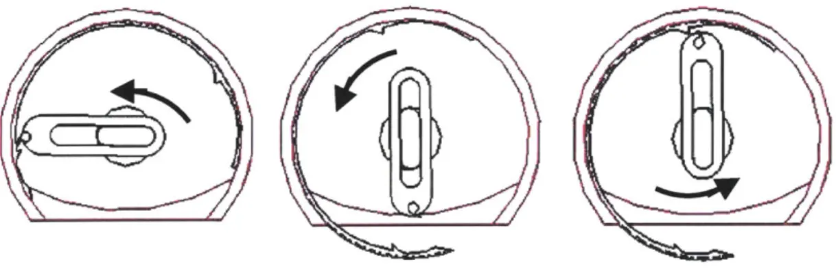
describes this challenge. When the hook reaches point B it is rotated back to point A where it will repeat the process of guiding the needle. It thus alternates between pulling the needle by its head and pushing it by its tail to complete one revolution of the needle. Meanwhile, the shaft undergoes three movements per suture:
1) Movement 1: To move hook from position A to position B to pull head of needle. 2) Movement 2: To return hook to position A
3) Movement 3: To move hook from position A to position B to push tail of needle
Though the concept of the fixed trajectory seemed serendipitous, the intricate three-step-movement of the shaft per suture was considered cumbersome and required more thought and concentration to operate than a
surgeon can afford to give. The design
also required that the user rotate a . 3
handle in order to drive the needle thereby dismissing the one-handed requirement that was highlighted in the design constraints. Efforts were made first to counter the three step movement of the handle since this was the most concerning.
The needle design in Design Concept 1 was altered such that it enabled continuous circular motion around the device. This allowed a single 360 degree rotation of the central shaft to guide the needle through one round of suturing. Additional design features were added that allowed a hook to drive the new needle. Design Concept
1 is discussed below.
I
Ll?~/,
/r
T4
f ,
Figure 8.0 Initial Blanco-Mead Continuous Circular Motion concept. Dated 1992
Figure 9.0 shows a conceptual representation of the altered Blanco-Mead Design. The tube A represents the pencil-sized body of the probe. It is shown flat on the bottom, indicating the location of the probe that sits parallel to the targeted defect. The needle B rests in a groove within this tube. A central shaft C runs through the tube providing a connection between the remote operator and the needle within. A housing D mounted on the shaft contains a hook E aligned coplanar with the needle. Entrapments on the needle
A
B
F
D E
Figure 9.0 Conceptual Representation of altered Blanco-Mead Design: Design Concept 1
allow the hook to latch onto them, in turn driving the needle. A ledge F at the bottom of the tube enables a CAM action that gently discontinues the circular motion of the hook and guides it over the defect. Since the extremely small size of the actual device would make any testing and redesign challenging, the initial device was dimensioned for a large-scale prototype. Figure 10.0 lists a detailed description of the individual parts of the suturing portion of the device.
. ... ~..j,.Lb,- .IIIIII i........
Needle: is a 2700 arc with nodes close to the head and the tail of the needle. These nodes serve as entrapments for the hook, which latches onto them, in turn driving the needle. It was proposed to have a swaged end for the thread, but for the means of a prototype, the thread was initially glued to the eye of the needle and later to a groove on the inner surface of the needle.
Housing: is an aluminum casing that serves to connect
the shaft to the hook. It is spring loaded to enable the CAM activated-motion of the hook. It is also constrained
by two springs in the vertical direction (not shown in
figure)
Ledge: guides the hook in a horizontal trajectory as it
reaches the bottom of the tube. This prevents the hook from contacting the skin that lays flush with the bottom of
the tube.
Hook: is a cylindrical rod that is flattened at one end and
bent to form a hook. It is inserted into the housing through a hole drilled on the latter's surface. It is held in place using a set screw.
Shaft: is a cylindrical rod that is milled on one end to
accommodate the housing such that the outer face of the latter remains flush with the outer diameter of the shaft
Figure 10.0 Main components of the sewing mechanism
The shaft is rotated to move the hook round the circumference of the tube, and in the process drives the needle through one revolution. Graspers would need to be used to manipulate the tissue. Figure 11.0 shows a pictorial cross-sectional simulation of one round of suturing.
Figure 11.0 Pictorial representation of Continuous Circular motion of needle
Since the needle rotating mechanism was considered the most crucial part of the device, the actuation of the rotation, thread manipulation, knotting mechanism and ergonomics of the device were not focused on until a solid needle mechanism was decided upon.
Prototype I
The first prototype built to test Concept 1 had an external tube diameter of 3 inches (a scale factor of 7 times the original size). The lexan tube was milled to get the appropriate features. Aluminum was used for all metal parts. The housing was milled on a CNC milling machine. The shaft and the grooves for the E-clips on it were turned on a lathe. The handle was cut on a water jet and assembled. After several computations, the
prototype proved that the continuous circular motion concept worked well. When driven by a large handle, the hook was able to drive the needle through a revolution. A
photograph of the prototype is shown in figure 12.0, followed by a photographic proof of concept of the CCM method in figure 13.0.
Figure 12.0 Photograph of large-scale prototype
Figure 13.0 First needle built for
Figure 14.0 CCM Proof of Concept
Challenges
The prototype however highlighted a feature that had been overlooked and
underestimated in the initial design concept- the topology of the thread. This turned out to be the biggest challenge of this phase of the project.
Just as manual stitching involves the monotonous yet crucial step of pulling on the thread such that it pulls taut on the material, a suturing device requires that the thread be pulled through the skin with each suture. Various methods were tried, but all resulted in a failure to pull the thread back all the way into body of the tube, without entanglement with the other components within. An alternative was to pull the thread in the opposite direction away from the tube, which would not be possible without the introduction of additional moving joints. In keeping with the aim to keep the design simple, this idea was
abandoned. An inbuilt suture spool located at the tail end of the needle was considered. This was also abandoned due to the requirement for high quality miniature parts. Other
solutions were attempted to solve the challenge of the entangled thread. Figures 15(a) and 15(b) below illustrate two concepts that were tried:
Figure 15(a) A tube was placed in a slot within the outer tube to contain the thread as it is pulled in via a hook. A
simple bent rod was used for a hook. The tube successfully contained the thread, however the setup required an
intelligent hook capable of automatic grasping and releasing the thread.
Figure 15(b) This led to the design of an intelligent hook as shown. The moving joints allowed easy opening and closing of the hook. The prototype proved the
concept however this idea was abandoned due to the miniature size of the hook that was required which demanded additional moving joints. Also shown is a photograph of the hook.
Figure 15.0 Attempts to solve the challenge of topology of thread
It was noted that the thread provided the least resistance to pulling, if it were pulled perpendicular to the axis of the needle, as opposed to the parallel motion it was being pulled in. This meant that the thread would be pulled perpendicular to the axis of the tube, i.e outward from the tube and not contained within the tube similar to the idea of pulling the thread out of the tube, incorporating this idea also required the use of additional moving parts.
3.3.2. Design Concept 2: CCM with altered orientation of needle
In Design 2, to avoid the issue of moving parts and achieve the perpendicular relationship between the planes of the needle and the hook, the orientation of the needle was changed from being parallel to the axis of the tube, to being perpendicular to the axis. This
concept is illustrated in Figure 16.0 below.
Figure 16.0 Altered Orientation of needle - thread pulled perpendicular to axis of needle
This allows a hook to pull the thread perpendicular to its axis, while at the same time, being encased within the housing of the tube. Simultaneously, a rack and pinion concept was proposed to address the challenge of the. The assembly would convert a vertical movement of a surgeon's thumb to the rotational movement required by the needle. However, before a second prototype was made to test this assembly and design concept 2, some other ideas were explored. It was felt that the number of parts in the current
prototype was too high and still increasing. Some parts such as the constraining springs on the housing seemed redundant. The assembly was not very robust. A device with minimal moving parts is robust, since very little can go wrong.
In addition, the nature of the stitches that was produced by this device was questionable. The continuous single stitches were easy to deposit, but were equally easy to remove. This is not a characteristic that is desirable in surgery. Surgeons require that the suture be sturdy in order to hold the apposition together until the tissues adhere naturally. A
stronger, firmer suture was required that did not have an underlying domino effect. Given all these disadvantages, it was decided that the continuous circular motion needle may not be the most convenient mechanism and the design process was restarted. This brought us to Design Concept 3.
3.3.3. Design Concept 3: Double Chain Stitch with hooked 180 degree needle
Design Concept 3
investigates and builds on another concept that was
initiated by Professor Blanco in 1991. This device deposits a continuous locked double
chain stitch in the defect,
very similar to a sewing machine. A dated rendering of the device and its working mechanism as sketched by Professor Blanco is shown in figure 17.0.
\
A:, 'N- v 7
~Yt)4
((~
Figure 17.0 Double Chain stitch
suture device conceived by Professor Ernesto Blanco.
Source: Blanco's notes dated
1991.
j TL ZE-A
(E)--5TSTCHE R
-- -AQJU-Su-r U E
-The device uses a circular needle that is different in function and structure to the needle described thus far. It does not exhibit a continuous circular motion feature similar to the Blanco-Mead concept; instead it moves in two half revolutions to complete one suture. It is different however in that a hook is not required to drive the needle. Also, a simple pistol grip with a trigger mechanism actuates the needle. The design of the external suture pool does away with the huge challenge of the topology of the thread. Since the thread is pulled from a spool as and when it is needed, the entire body of the thread does not need to be pulled through the defect each time. This also increases safety of the device by minimizing the amount of material that re-enters the device after contact with the body. The simplicity of the proposed concept and its remarkably low number of moving parts rendered it very attractive.
Given the above promising characteristics, design concept 3 aimed to build on the idea and test the theory. Having rendered an exterior look for the overall device, efforts were immediately focused on the sewing feature of the device. Figure 18.0 shows an initial rendering of the overall device.
Sewing feature of device
The sewing feature of the device consists of a needle mounted on a pulley that is driven by a stainless steel cable. The cable is attached to a mounted tension spring on one end, and to the trigger of the handle at the other. A rough setup is illustrated in Figure 19.0.
Figure 19.0 Sketch showing driving components of the needle
The intriguing needle in this device is a 180 degree arc extending toward the center of the needle. The end of the needle, unlike its two predecessors does not have a groove for thread attachment. The needle is not permanently attached to the thread. The front end of the needle is pointed so as to help penetration through the skin. Behind this front end, is a purposeful hook which forms the basis of the entire design and determines the success of
the needle and hence the device. Figure 20.0 show s a close up of the needle followed by a rendition of how the needle works in theory
in Figure 19.0.
49
Figure 21.0 Rendition of workings of the needle (cross section). incorporation of thread into the process.
Also shows
Prototype 3
Before a considerable amount of time was exhausted on prototyping the whole device, it was decided to build a prototype of the needle first. The needle was cut on a waterjet
similar to its predecessors, and was mounted on a wooden stand. Figure 22.0 shows a picture of the first needle.
. ........................-.- -0 0 7f, .. --- - - ..
Figure 22.0 Photograph of the first needle.
The needle worked well in theory and in practice. It was able to successfully move through low density foam, pick up thread and bring it back to its point of origin. The sewing process was not carried any further. Challenges however cropped up when chicken breast was used to simulate skin. It was noted that the hook of the needle
successfully picked up and delivered thread however the sharp retreating hook served as an open shear and was found to tear the skin.
More alterations were required if the skin were to be protected. Several permutations of the shape of the hook followed:
3.3.3.1 Design 3b: Hook with Closing Wire
Hook with closing wire: it was decided to cover the shears of the hook by attaching a wire to the needle. This action is shown in simple terms in figure 23.0 below.
However, this idea was abandoned due to the following reasons:
- the closing wire motion demanded accurate timing synchronized with needle motion throughout mechanism. This would be challenging when the device were
miniaturized.
- The closing wire also added to the number of moving joints in the body cavity. This is always an unsafe characteristic.
0U-IF - 1 -~~ --
-STITCHING SEQUENCE; PARALLEL LAYERS OF RATERIAL
Needle Closing re Empty needle penetrotes
4
C1os open Hook is opened Coa-!low thread 1oop
tc siae .Jwnrd Neele hooks thread below jng wire s hook on Needle penetrates agoln. Previous lOop s.lides along needle.
Hook catches new
chread section.
Wire
clos ing: ook
Wre closes hook
opening and than retraces Needle putts thread across layers hook is closed by closing wire
d-i
Need e advarce pvL ng tflre acNeedle retracts asair
pulling threaa tnroau
previous lcp a. forming the
Chan-Statrhe lot then advar::es rune c
Figure 23.0 Design of a hook with closing wire. Source: Blanco's notes dated 1991
3.3.3.2. Design 3c: Hook curved into Needle
Concept 3c returned to the initial hook in design concept 3, with a minor alteration made to it. The pointed end of the hook was curved in as shown in figure 24.0, so as to blunt out the shear effect of the retreating hook. Point A would now act as a fulcrum enabling the hook to bend into the needle as the latter recedes through the skin. This bending action also ensures that the thread is
carried safely to the other side.
A
Figure 24.0 Curved hook needle -I
Prototype 3c
For prototype 3c, the waterjet method was abandoned since the flat nature of the needle did not allow forces to be uniformly distributed, and this was not an accurate
representation of how the cylindrically shaped needle would react to stimulating forces in the real device. Metal wire was annealed and bent to give the appropriate shape. The hook was tic-welded.
The revised needle was tested by placing it on a mount. Chicken meat was used again. The needle was successful this time, in receding through the skin without shearing it. The suturing process was then taken to the next step, and the needle was moved along the meat specimen to start the next suture. This however was not successful. The placement of the hook on the inside surface of the needle did not allow it to retain the loop as it progressed along the specimen. This is required for a chain stitch. This was a feature that was not obvious in the 2-D sketches.
L
K
K
r
K
/p
K-I
4-K
C
Figure 25.0 3-D topological feature that was ignored in 2-D sketches
Figure 26.0 Mounted setup of needle with hook on inner surface
3.3.3.3 Design 3d: Curved Hook On Outer Face of Needle
It was deduced that placing the hook on the outer surface of the needle would solve this problem. The needle was altered to accommodate this feature.
Prototype 3d
The hook on the outer face of the needle did indeed solve the topological
challenge. The loop was retained whilst the needle moved along the wound to its next point of penetration. The needle however still needed to be tugged so as to release the thread at the appropriate time. This was considered a minor issue
that could be solved easily by a simple Figure 27.0 New curved hook on outer face of nee modification of the hook. Further testing of Prototype 3d however showed another grave concern that again had been overlooked causing a great setback in the design process.
A