HAL Id: in2p3-00355719
http://hal.in2p3.fr/in2p3-00355719
Submitted on 23 Jan 2009HAL is a multi-disciplinary open access
archive for the deposit and dissemination of sci-entific research documents, whether they are
pub-L’archive ouverte pluridisciplinaire HAL, est destinée au dépôt et à la diffusion de documents scientifiques de niveau recherche, publiés ou non,
(PCDL) Task
P. Eliasson, T. Ekelof, Anthony Ferrari, V. Ziemann, M. Alabau Pons, P.
Bambade, J. Brossard, S. Cavalier, O. Dadoun, G. Le Meur, et al.
To cite this version:
P. Eliasson, T. Ekelof, Anthony Ferrari, V. Ziemann, M. Alabau Pons, et al.. Results of the EUROTeV Post Collision Line Design (PCDL) Task. 2008, pp.1-9. �in2p3-00355719�
Results of the EUROTeV Post Collision Line Design
(PCDL) Task
P. Eliasson, T. Ekel¨of, A. Ferrari, V. Ziemann,
Uppsala University, Sweden
M. Alabau Pons, P. Bambade, J. Brossard, S. Cavalier, O. Dadoun, G. Le Meur, F. Touze,
Laboratoire de l’Acc´el´erateur Lin´eaire, Orsay, France
D. Angal-Kalinin,
CCLRC, ASTeC & Cockcroft Institute, United Kingdom
R.B. Appleby,
University of Manchester & Cockcroft Institute, United Kingdom
J. Carter,
John Adams Institute & Royal Holloway, University of London, United Kingdom
O. Napoly,
CEA/DSM/DAPNIA Saclay, France
November 14, 2008
Abstract
This paper is the deliverable of the EUROTeV Post Collision Line Design (PCDL) task and gives an overview of the published results.
1 Introduction
At high-energy e+e− linear colliders, the incoming beams must be focused to extremely
small spot sizes in order to achieve high charge densities and, in turn, to reach the desired luminosity. As a result, the colliding beams experience very strong electromagnetic fields at the interaction point (IP). The subsequent bending of their trajectories leads to the emission of beamstrahlung photons, which may then even turn into e+e− pairs. This
leads to an emittance growth as well as a large energy spread for the outgoing beams. In the EUROTeV framework, the PCDL task aims at a conceptual design of the post-collision beam line between the IP and the final beam dump for:
• the International Linear Collider (ILC),
• the multi-TeV Compact Linear Collider (CLIC).
This report summarizes the beam dynamics simulation results obtained to complete this task. In addition, suitable instrumentation options in order to measure relevant IP beam parameters, and especially luminosity-related signals, are discussed.
2 ILC studies
The study of the ILC extraction line has been pursued in EUROTeV within an interna-tional design team, as part of the Global Design Effort (GDE) responsible for the ILC Technical Design Phase. In this context, several designs with different crossing angles between the beams at the IP have been examined, emphasizing different aspects both of the beam line design and of detector and physics capabilities.
The baseline configuration chosen for the ILC consists of a single IP with a crossing angle of 14 mrad. While this layout allows more convenient spent beam extraction and hence also makes the spent beam easier to use for diagnostics purposes (a desirable feature for instance to enable additional post-IP beam polarisation and energy measure-ments), it adds some complexity to the incoming beam dynamics and a dependence on an effective crab-crossing scheme to deliver the full luminosity. Alternative designs with either head-on collisions or a very small crossing angle of 2 mrad have been studied to mitigate these disadvantages. These designs trade simpler pre-collision dynamics for increased extraction difficulty and also allow better calorimetric coverage in the very forward region of the detector, which is critical for part of the ILC physics program, and easier calibration procedures to monitor field distortions in the tracking volume of the detector, which matters to achieve optimum track resolution in case a large Time Projection Chamber is used.
The PCDL task mainly focused on establishing a credible and economical minimal de-sign for the 2 mrad alternative scheme. The initial dede-sign [1a-b] attempted to include special optics for additional post-IP energy and polarisation measurements, as in the
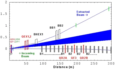
baseline 14 mrad layout. It however proved inadequate as it could not cover all specified ILC beam parameters and turned out too complex and expensive. The improved design [2a-b] minimises the number of magnets in order to reduce costs and incorporates a flexibility in the overall geometry in order to accommodate various dump layouts under discussion. It does not include the originally planned additional energy and polarisation diagnostics, but the possibility exists to add such measurements in future upgrades and with novel techniques. Figure 1 shows a schematic layout of this design.
Figure 1: Schematic layout of the 2 mrad ILC extraction line.
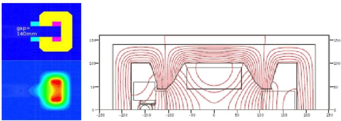
Using tracking studies of beam losses with high statistics to optimise the superconduc-tive part of the final doublet [3a-b] and the downstream optics [4a-b], and expected beamstrahlung losses evaluated in realistic conditions [5] to determine beam stay-clear requirements, it was shown that acceptable power losses and magnet parameters could be obtained for the full range of specified ILC beam parameters. High-statistics beam tracking was also pursued to explore possibilities of inferring beam transverse sizes and offsets at the IP for tuning purposes, by measuring the spent beam tail profiles at a few well-chosen protection collimators [6]. Known techniques to detect secondary emission currents off Tungsten wires or Titanium strips built into the collimator, or newer ideas to count Compton scattering from showers in a distant absorber, could then be used to instrument these collimators. Finally, the higher-order chromatically-corrected final focus optics was successfully re-fitted to integrate the 2 mrad extraction line, including the effects of fringe field from a few closely located extraction line magnets. Preliminary designs of all warm magnets allowed checking their feasibility. As an example of the latter, the physical geometry and magnetic field lines of the C-shaped large aperture bending magnet BHEX1 and of the large aperture quadrupole magnet QEX1 are shown in Figure 2. The superconductive quadrupole and large aperture sextupole in the final doublet are based on NbTi technology and are scaled from similar designs for LHC and the initial 2 mrad layout.
Figure 2: Left: Physical geometry and field lines of the BHEX1 bending magnet. For the incoming beam passing at 27 cm to the left of the extracted beam, the only component of the leakage field of any significance is the quadrupole. It can be absorbed by re-fitting the final focus optics. Right: Field lines in the QEX1 quadrupole, which is located at the entrance of the 2 mrad ILC extraction line: for the incoming beam line on the left-hand side part of the quadrupole, the magnetic field remains smaller than 10 G.
The PCDL task also included an evaluation of the rate of back-scattered photons into the ILC detectors from beam losses along the extraction line, as well as of their impact to background hits in the first layers in the vertex detector [7], benchmarking studies of different beam tracking codes and comparisons of beam losses in the earlier designs of the different extraction lines [8a-d], contributions to the alternative head-on design, to estimate power losses in the sensitive electrostatic separators and to evaluate the luminosity reduction from parasitic collisions [9a-d], and a dedicated beam parameter and performance optimisation for the e-e- mode of operation [10a-b].
3 CLIC studies
At CLIC, the incoming beams a much larger energy and a much smaller emittance than at ILC. The beamstrahlung emission is therefore far more important and, in contrast with ILC, a significant number of e+e− coherent pairs are also produced. We started our
studies by investigating the suitability of the 20 mrad configuration of the ILC extraction beam line optics for the CLIC post-collision line for CLIC and showed that such a design is not adapted to CLIC, because of the larger amount of low-energy particles found in both the disrupted beam and the coherent pairs, which would lead to much larger power losses than at ILC [11]. Indeed, if there are quadrupoles in the post-collision line and if their focusing strength is adapted for the main beam, then the low-energy tail of the beam is over-focused and lost downstream. This triggered an investigation into a simpler beam line design without any beam focusing elements [12].
The CLIC post-collision line design has to ensure safe propagation of the colliding beams with large momentum and angular spread to their dump, but it must also transport par-ticles even when beams are not colliding, which favors a long post-collision line in order to maximize the beam spot size on the exit window. A further difficulty comes from the fact that e+e− coherent pairs are generated with energies peaking at about 10%
of the primary beam energy: these particles need to be transported and dumped in a coordinated way in order to prevent large power losses and the generation of background in the detector at the IP, through back-scattered particles.
In our design, the CLIC post-collision line mainly consists of a vertical dog-leg chicane which displaces the main disrupted beam downwards by a few cm and the wrong-sign charged particles of the e+e− coherent pairs upwards. These are not transported until
the final dump, but absorbed in an intermediate dump, placed about 50 m for the IP. A first design was reported in [13a-b] but, following changes of the CLIC beam parameters, it was revised and then updated in [14]. Figures 3 and 4 respectively show a general layout of the CLIC post-collision line and the beam profiles at the final dump.
Interaction Point
Beamstrahlung photons Main (disrupted) beam charged particles
Dump for wrong−sign
Final dump
Vertical bend
Vertical bend
Figure 3: Schematic layout of the CLIC post-collision line.
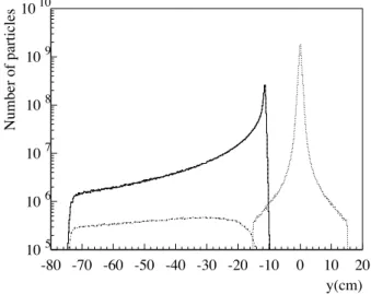
105 106 107 108 109 1010 -80 -70 -60 -50 -40 -30 -20 -10 0 10 20 y(cm) Number of particles
Figure 4: Vertical profiles for the charged beam (full line), including the particles of the e+e− coherent pairs with the right-sign charge (dashed line), and for the
beamstrahlung photons (dotted line), as obtained at the end of the CLIC post-collision line, 150 m downstream of the IP.
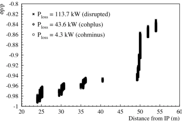
Figure 5 shows the distribution of the power losses along the CLIC post-collision line. Most of them occur in the collimators placed between the first magnets, as well as in the intermediate dump. In the first magnets, less than 100 W/m are deposited and, in the four magnets placed behind the intermediate dump, the beam transport is loss free.
-1 -0.98 -0.96 -0.94 -0.92 -0.9 -0.88 -0.86 -0.84 -0.82 -0.8 20 25 30 35 40 45 50 55 60 Ploss = 113.7 kW (disrupted) Ploss = 43.6 kW (cohplus) Ploss = 4.3 kW (cohminus) Distance from IP (m) δp/p
Figure 5: Relative energy spread of the lost particles as a function of the position of loss in the CLIC post-collision line, obtained when tracking the charged beams. The wrong-sign charged particles absorbed in their dump are not shown.
The dog-leg chicane consists of wide-aperture normal-conducting magnets of 4 m in length, with a field of approximately 1 T. The chicane has the added benefit to separate the main disrupted beam from the beamstrahlung photons by 11 cm. This allows use of the beamstrahlung photons for diagnostics purposes in a beamstrahlung detector sensitive to muon-pairs generated in the beam dump and placed behind it, see Figure 6.
Primary beam
Muons Mirror
Photo multiplier
Water beam dump
Beamstrahlung photons Converter Gas Cerenkov detector Extra shielding Muons from the
shower cascade of the primary beam
Figure 6: Cerenkov beamstrahlung detector based on the conversion of high-energy beamstrahlung photons into muon pairs, that are the only charged particles penetrating the beam dump and can be detected by their emission of Cerenkov light in a gas detector. Note that the high-energy muons generated by the pri-mary beam are predominantly forward peaked and miss the Cerenkov detector.
Furthermore, the wrong-sign charged particles of the e+e− coherent pairs are deflected
upwards in the first magnets, which allows them to collect and analyse them in the intermediate beam dump, for diagnostics means. A fraction of the disrupted beam will be lost in collimators that are placed between the first four chicane magnets. Instru-menting these collimators with e.g. embedded pin-diodes or scintillation counters will allow detection of the low-energy particles produced during the collision. A summary of several diagnostics is given in [15].
Finally, we have performed a design of the exit window at the end of the post-collision line, which has to sustain the full load of the 14 MW beam power on top of being rather thick to cope with the pressure difference. We found that a design similar to the one chosen for the LHC beam dump window is suitable. We propose an exit window made of a thick layer of carbon-carbon composite, with a thin aluminum leak-tight foil [16].
4 List of publications
[1a] R. Appleby et al., Optics of the ILC Extraction Line for 2 mrad Crossing Angle, EuroTeV-Report-2006-001.
[1b] R. Appleby et al., The 2 mrad crossing-angle interaction region and extraction line, EuroTeV-Report-2006-053.
[2a] R. Appleby et al., Improved 2 mrad crossing angle layout for the International Lin-ear Collider, EuroTeV-Report-2007-022.
[2b] R. Appleby et al., The 2 mrad crossing angle scheme for the Internation Linear Collider, EuroTeV-Report-2008-034.
[3a] R. Appleby and P. Bambade, Improved final doublet designs for the ILC base-line small crossing-angle scheme, EuroTeV-Report-2006-022, also published in JINST 1, P10004 (2006).
[3b] R. Appleby et al., Improved Final Doublet Parameters for the ILC 2 mrad Crossing Angle Interaction Region, EuroTeV-Memo-2007-001.
[4a] R. Appleby et al., Panofsky Quadrupole Parameters for the ILC 2 mrad Alternative Crossing Angle Scheme, EuroTeV-Memo-2007-005.
[4b] R. Appleby et al., Extraction Line Optics for the Improved 2 mrad ILC Crossing Angle Layout, EuroTeV-Memo-2007-004.
[5] R. Appleby and P. Bambade, Photon production at the interaction point of the ILC, EuroTeV-Report-2007-014, arXiv:0803.3519.
[6] J. Brossard et al., EuroTeV-Report in preparation.
[7] O. Dadoun and P. Bambade, Backscattering of secondary particles into the ILC de-tectors from beam losses along the extraction line, EuroTeV-Report-2007-047.
[8a] A. Ferrari and Y. Nosochkov, Beam Losses in the Extraction Line of a TeV e+e-Linear Collider with a 20 mrad Crossing Angle, EuroTeV-Report-2005-025.
[8b] A. Ferrari and Y. Nosochkov, Power losses in the ILC 20 mrad extraction line at 1 TeV, EUROTeV Report 2006-080.
[8c] R. Appleby et al., Particle tracking in the ILC extraction lines with DIMAD and BDSIM, EuroTeV-Report-2005-026.
[8d] R. Appleby, et al., Benchmarking of tracking codes (BDSIM/DIMAD) using the ILC extraction lines, EuroTeV-Report-2006-038.
[9a] J. Brossard, P. Bambade and O. Napoly, Power Loss Estimation in the Electrostatic Separators of the ILC Alternative Head-on Scheme at 500 GeV in the Center-of-Mass, EuroTeV-Memo-2007-003.
[9b] J. Brossard et al., Evaluation of luminosity reduction in the ILC head-on scheme from parasitic collisions, EuroTeV-Report-2007-052.
[9c] O. Napoly et al., Technical challenges for head-on collisions and extraction at the ILC, EuroTeV-Report-2007-043.
[9d] R. Appleby et al., Design of an interaction region with head-on collisions for the ILC, EuroTeV-Report-2006-083.
[10a] M. Alabau Pons et al., Optimization of the e- e- option for the ILC, EuroTeV-Report-2006-067.
[10b] M. Alabau Pons et al., Comparison of ILC Fast Beam-Beam Feedback Performance in the e-e- and e+e- Modes of Operation, EuroTeV-Report-2007-053.
[11] A. Ferrari, Power losses of a nominal CLIC beam in the ILC 20 mrad extraction line, EUROTeV Report 2006-019.
[12] T. Ekel¨of, P. Eliasson, A. Ferrari and V. Ziemann, First design of a post-collision line for CLIC at 3 TeV, EUROTeV Report 2006-023.
[13a] A. Ferrari, Conceptual design of a post-collision transport line for CLIC at 3 TeV, EUROTeV Report 2007-001.
[13b] A. Ferrari, New concept for a CLIC post-collision extraction line, EUROTeV Re-port 2007-023.
[14] A. Ferrari, Impact of the new CLIC beam parameters on the design of the post-collision line and its exit window, EUROTeV Report 2008-021.
[15] V. Ziemann, CLIC Post-collision Diagnostics, EUROTeV Report 2008-016.
[16] A. Ferrari and V. Ziemann, Conceptual Design of a Vacuum Window at the Exit of the CLIC Post-Collision Line, EUROTeV Report 2008-009.
Acknowledgements
This work is supported by the Commission of the European Communities under the 6th
Framework Programme ”Structuring the European Research Area”, contract number RIDS-011899.