Distributed Wake-Body Resonance of
a Long Flexible Cylinder in Shear Flow
The MIT Faculty has made this article openly available.
Please share
how this access benefits you. Your story matters.
Citation
Bourguet, Rémi, Michael S. Triantafyllou, Michael Tognarelli,
and Pierre Beynet. “Distributed Wake-Body Resonance of a Long
Flexible Cylinder in Shear Flow.” ASME 2012 31st International
Conference on Ocean, Offshore and Arctic Engineering, 1-6 July,
2013, Rio de Janeiro, Brazil, ASME, 2013. © 2012 ASME
As Published
http://dx.doi.org/10.1115/OMAE2012-83294
Publisher
ASME International
Version
Final published version
Citable link
http://hdl.handle.net/1721.1/120738
Terms of Use
Article is made available in accordance with the publisher's
policy and may be subject to US copyright law. Please refer to the
publisher's site for terms of use.
DISTRIBUTED WAKE-BODY RESONANCE OF A LONG FLEXIBLE CYLINDER
IN SHEAR FLOW
R ´emi Bourguet∗
Institut de M ´ecanique des Fluides de Toulouse Toulouse, France
Email: [email protected]
Michael S. Triantafyllou
Massachusetts Institute of Technology Cambridge, MA, USA
Email: [email protected]
Michael Tognarelli
BP America Production Co. Houston, TX, USA
Email: [email protected]
Pierre Beynet
BP America Production Co. Houston, TX, USA Email: [email protected]
ABSTRACT
The fluid-structure interaction mechanisms involved in the development of narrowband and broadband vortex-induced vi-brations of long flexible structures placed in non-uniform cur-rents are investigated by means of direct numerical simulation. We consider a tensioned beam of aspect ratio 200, free to move in both the in-line and cross-flow directions, and immersed in a sheared flow at Reynolds number 330. Both narrowband and broadband multi-frequency vibrations may develop, depending on the velocity profile of the sheared oncoming current.
Narrowband vibrations occur when lock-in, i.e. the synchro-nization between vortex shedding and structure oscillations, is limited to a single location along the span, within the high cur-rent velocity region; thus, well-defined lock-in versus non-lock-in regions are noted along the span. In contrast, we show that broadband responses, where both high and low structural wave-lengths are excited, are characterized by several isolated regions of lock-in, distributed along the length. The phenomenon of dis-tributed lock-in impacts the synchronization of the in-line and cross-flow vibrations, and the properties of the fluid-structure en-ergy transfer, as function of time and space.
∗Address all correspondence to this author.
INTRODUCTION
Vortex shedding in the wake of a riser or cable subject to a cross-flow current induces unsteady fluid forces on the struc-ture, resulting in structural vibrations and stresses that can cause fatigue damage.
The case of a rigid circular cylinder free to move, or forced to oscillate within a uniform current, has served as a canonical problem to investigate VIV mechanisms (Bearman, 1984; On-goren & Rockwell, 1988; Sarpkaya, 2004; Williamson & Go-vardhan, 2004; Carberry et al., 2005; Prasanth & Mittal, 2008; Bearman, 2011). Large amplitude oscillations occur when the frequency of vortex formation is relatively close to a natural fre-quency of the structure; then the frefre-quency of vortex shedding can be entrained and become equal to the frequency of the struc-tural vibration. This condition of wake-body resonance is re-ferred to as lock-in.
The increased complexity of the VIV phenomenon in the case of slender flexible bodies immersed in sheared currents, has been highlighted in recent experimental and numerical works (Trim et al., 2005; Lie & Kaasen, 2006; Lucor et al., 2006; Van-diver et al., 2009; Bourguet et al., 2011a). Mono-frequency as well as multi-frequency structural responses have been reported in this context (Chaplin et al., 2005; Bourguet et al., 2011b). The occurrence of multi-frequency vibrations may significantly
im-Proceedings of the ASME 2012 31st International Conference on Ocean, Offshore and Arctic Engineering OMAE2012 July 1-6, 2012, Rio de Janeiro, Brazil
pact the fatigue life of the structures. However, previous studies were limited to narrowband vibrations and the case of broadband responses, where both high and low structural wavenumbers are excited, still remains to be investigated.
We address this problem of broadband response using de-tailed numerical simulation results. The objective is to ana-lyze the fluid-structure interaction mechanisms associated with broadband VIV in non-uniform current, with an emphasis on the lock-in phenomenon and its impact on the energy transfer be-tween the flow and the body.
The physical model and numerical method are briefly de-scribed in a first section. The structural vibrations are analyzed in a second section. Lock-in and fluid-structure energy transfer are examined in a third section. The main findings of this study are summarized in a fourth section.
PHYSICAL MODEL AND NUMERICAL METHOD
The flow past a flexible cylinder of circular cross-section is predicted using direct numerical simulation of the three-dimensional incompressible Navier-Stokes equations. The cylin-der is submitted to a cross-flow which is parallel to the global x axis and sheared along the global z axis. Two types of sheared profiles, linear and exponential, are used as shown in Fig. 1. In both cases, the ratio between the maximum and minimum on-coming flow velocities is set to 3.67. In the following, all
physi-cal variables are non-dimensionalized using the cylinder diame-ter D and the maximum inflow velocity U , which occurs at z= 0.
The Reynolds number (Re) based on D and U is equal to 330. The cylinder aspect ratio is L/D = 200, where L is the
cylin-der length in its equilibrium position in quiescent fluid. It is pinned at both ends, while it is free to move in both the in-line (x) and cross-flow (y) directions. The cylinder mass ratio, de-fined as m=ρc/ρfD2, whereρc is the cylinder mass per unit length andρf the fluid density, is set to 6. The constant ten-sion, bending stiffness and damping of the structure are desig-nated by T , EI and K, respectively. The in-line and cross-flow displacements of the cylinder are denoted byζxandζy. The sec-tional drag and lift coefficients are defined as Cx= 2Fx/ρfDU2 and Cy= 2Fy/ρfDU2, where Fxand Fyare the in-line and cross-flow dimensional fluid forces. The structural dynamics are gov-erned by a tensioned beam model, expressed as follows in non-dimensional form (Evangelinos & Karniadakis, 1999):
∂2ζ ∂t2 −ω 2 c ∂2ζ ∂z2 +ω 2 b ∂4ζ ∂z4 + K m ∂ζ ∂t = 1 2 C m, (1)
where ζ = [ζx,ζy]T and C= [Cx,Cy]T. t denotes the non-dimensional time variable.ωcandωb, the cable and beam phase velocities defined asωc2= T /m andω2
b= EI/m, are set to similar values in both cases,(ωc,ωb) = (4.55, 9.09) in the linear profile
case and(ωc,ωb) = (5, 10) in the exponential profile case. The structural damping is set equal to zero (K= 0) to allow
maxi-mum amplitude oscillations. These structural parameters lead to vibrations involving high structural wavenumbers, which are rep-resentative of configurations encountered in the context of ocean engineering (Trim et al., 2005).
The parallelized code Nektar, based on the spectral/hp el-ement method (Karniadakis & Sherwin, 1999), is used to solve the coupled fluid-structure system. A boundary-fitted coordinate formulation is used to take into account the cylinder unsteady deformation. The version of the code employs a hybrid scheme with Fourier expansion in the spanwise (z) direction and Jacobi-Galerkin formulation in the (x, y) planes. Validation studies of
the numerical method have been reported in previous works con-cerning similar physical configurations (Newman & Karniadakis, 1997; Evangelinos & Karniadakis, 1999; Bourguet et al., 2011a). The present simulations involve approximately 0.6× 10⁹degrees of freedom. The results reported in this study are based on time series of more than 300 convective time units, collected after the initial transient dies out.
NARROWBAND VERSUS BROADBAND MULTI-FREQUENCY RESPONSES
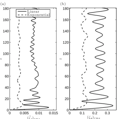
The typical structural vibrations observed in the cases of lin-ear and exponential shlin-ear profiles are illustrated in Fig. 2(a) and (b), respectively. Selected time series of the cylinder cross-flow displacement are presented. In both cases, the response is a mix-ture of standing and traveling wave patterns. The amplitude of oscillation in the case of exponential shear is approximately half the amplitude observed in the linear shear case, in both the in-line and cross-flow directions (Fig. 3). In these plots, only the deviations of the in-line motion from its mean value, ˜ζx, are con-sidered. In the case of linear shear, the underlying standing wave component leads to the formation of cells along the span corre-sponding to alternating ‘nodes’ (minima of the response enve-lope) and ‘anti-nodes’ (maxima of the response enveenve-lope). Such cellular patterns are not observed in the exponential shear case, due to a change in the nature of the responses, as shown in the following.
The response power spectral densities (PSD) are plotted in Fig. 4. Both cases exhibit multi-frequency vibrations but the structural responses differ by the excited frequency bandwidth and the range of excited wavenumbers: three main frequencies are excited along the span within a narrow band in the case of linear shear while a broadband response is observed in the ex-ponential shear case. Through spatio-temporal spectral analy-sis, each excited frequency can be related to the corresponding excited structural wavenumber. In the case of narrowband re-sponse, only high wavenumbers, corresponding to three adjacent sine Fourier modes, are excited. In the case of broadband vibra-tions, both high- and low-wavenumber responses are noted. The
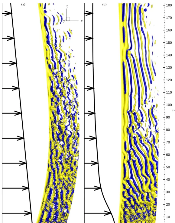
10 20 30 40 50 60 70 80 90 100 110 120 130 140 150 160 170 180 z (a) (b) x y z
FIGURE 1. INSTANTANEOUS ISO-SURFACES OF SPANWISE VORTICITY DOWNSTREAM OF THE CYLINDER: (a) LINEAR VELOCITY
PROFILE (ωz= ±0.3) AND (b) EXPONENTIAL VELOCITY PROFILE (ωz= ±0.15). PART OF THE COMPUTATIONAL DOMAIN IS SHOWN.
ARROWS REPRESENT THE SHEAR ONCOMING FLOW.
in-line responses also exhibit a clear narrowband or broadband character, depending on the oncoming flow velocity profile.
The in-line and cross-flow vibrations are non-linearly cou-pled by the fluid forces. The phase difference between the in-line and cross-flow displacements controls the shape and orien-tation of the beam trajectories in the plane perpendicular to the
span. The instantaneous phases of the in-line and cross-flow dis-placements (φxandφyrespectively) are determined by means of the Hilbert transform. Adopting an approach similar to Huera-Huarte & Bearman (2009), the phase differenceΦxyis quantified
Ti me z 0 10 20 30 40 50 0 20 40 60 80 100 120 140 160 180 ζy −0.6 −0.4 −0.2 0 0.2 0.4 0.6 (a ) Ti me z 0 10 20 30 40 50 0 20 40 60 80 100 120 140 160 180 ζy −0.3 −0.2 −0.1 0 0.1 0.2 0.3 (b )
FIGURE 2. TEMPORAL EVOLUTION OF CROSS-FLOW
DIS-PLACEMENT ALONG THE CYLINDER SPAN, IN THE CASES OF (a) LINEAR AND (b) EXPONENTIAL VELOCITY PROFILES.
as follows: Φxy= [pφx− qφy, mod 360o], (2) 0 0.005 0.01 0.015 0 20 40 60 80 100 120 140 160 180 ( ˜ζx)r m s z L i n ear E xp on enti al (a) 0 0.1 0.2 0.3 0 20 40 60 80 100 120 140 160 180 (ζy)r m s z (b )
FIGURE 3. RMS VALUE OF (a) IN-LINE DISPLACEMENT
FLUCTUATION AND (b) CROSS-FLOW DISPLACEMENT ALONG THE CYLINDER SPAN.
where p and q are two integer numbers defining the level of syn-chronization studied. As generally observed in this context, a ra-tio of 2 can be established between in-line and cross-flow excited frequencies; hence the couple(p, q) = (1, 2) is chosen here.
Val-ues ofΦxyin the range 0o− 180o(180o− 360orespectively) cor-respond to ‘figure eight’ orbits, where the beam moves upstream (downstream respectively) when reaching the cross-flow oscilla-tion maxima. These two types of trajectories are referred to as ‘counter-clockwise’ and ‘clockwise’, respectively (Dahl et al., 2007).
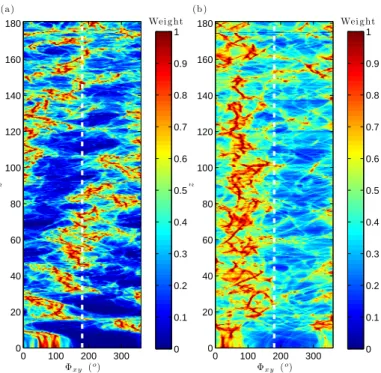
The histograms ofΦxyissued from the entire response time series are plotted along the span in Fig. 5, for both velocity pro-files. In the linear shear case, a predominant trajectory can be identified at each spanwise location (Fig. 5(a)). In this case, due to the pronounced standing wave character of the vibrations near
z= 0, transitions can be noted between counter-clockwise and
clockwise trajectories near the nodes of the in-line response. In the region where purer traveling waves develop, the phase differ-ence exhibits a well-defined, nearly-linear drift towards higher angles, as z increases. Counter-clockwise orbits dominate the synchronization pattern in the high velocity region. Significant differences can be noted in the case of broadband responses (Fig. 5(b)). Despite noisier histograms, it appears thatΦxy re-mains generally lower than 180o; hence, the in-line and cross-flow vibrations appear to be locked to a specific phase difference
Temp o ra l frequ en cy z 0.12 0.13 0.14 0.15 0.16 0.17 0.18 0.19 0 20 40 60 80 100 120 140 160 180 P S D - ζy 0.01 0.02 0.03 0.04 0.05 0.06 0.07 0.08 0.09 (a ) Temp o ra l frequ en cy z 0.05 0.1 0.15 0 20 40 60 80 100 120 140 160 180 P S D - ζy 0.005 0.01 0.015 0.02 0.025 0.03 0.035 0.04 (b )
FIGURE 4. SPANWISE EVOLUTION OF CROSS-FLOW
DIS-PLACEMENT PSD, IN THE CASES OF (a) LINEAR AND (b) EX-PONENTIAL VELOCITY PROFILES.
range and no drift can be identified along the beam.
Φx y (o) z 0 100 200 300 0 20 40 60 80 100 120 140 160 180 Wei ght 0 0.1 0.2 0.3 0.4 0.5 0.6 0.7 0.8 0.9 1 (a) Φx y (o) z 0 100 200 300 0 20 40 60 80 100 120 140 160 180 Wei ght 0 0.1 0.2 0.3 0.4 0.5 0.6 0.7 0.8 0.9 1 (b )
FIGURE 5. HISTOGRAM OF IN-LINE/CROSS-FLOW MOTION
PHASE DIFFERENCE ALONG THE CYLINDER SPAN, IN THE CASES OF (a) LINEAR AND (b) EXPONENTIAL VELOCITY PRO-FILES.
DISTRIBUTED LOCK-IN AND FLUID-STRUCTURE EN-ERGY TRANSFER
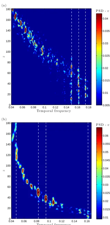
For long flexible structures, the lock-in condition is defined to exist at each spanwise location where the local vortex shed-ding frequency is synchronized with a cross-flow vibration fre-quency; otherwise, the condition is referred to as non-lock-in. A spanwise region which envelopes all the adjacent locked-in loca-tions is referred to as a lock-in region. The PSD of the cross-flow component of the flow velocity in the wake is used to identify the vortex shedding frequency along the span (Fig. 6).
In the case of linear shear (narrowband responses), a single lock-in region is found, located within the high current veloc-ity, while over the rest of the span vortex shedding and cylinder vibrations are not synchronized.
In contrast, the case of exponential shear (broadband re-sponses) exhibits a totally different behavior: the lock-in con-dition is not contained within a single region. Instead, lock-in is distributed over several isolated regions along the entire length of the body, and is not limited only to the high current velocity region. However, despite this difference, the lock-in phenomenon remains a locally mono-frequency event, viz. vor-tex shedding occurs principally at a single frequency at a given spanwise location. This was first noted in the case of narrow-band multi-frequency vibrations (Bourguet et al., 2011a). In the
narrowband case, the lock-in condition is generally established at the locally predominant vibration frequency. For broadband responses, the spanwise evolution of the lock-in frequency is driven by the Strouhal relation.
The wake patterns are composed of spanwise cells of con-stant vortex shedding frequency that induce an oblique orienta-tion of the vortex rows as they form, as well as vortex splittings between adjacent cells (Fig. 1). The vortex splittings are nec-essary to ensure the continuity of the vortex filaments while the vortex shedding frequency is discontinuous.
A comparison between the spanwise location of the lock-in region (Fig. 6(a)) and the lock-in-llock-ine/cross-flow synchronization pattern (Fig. 5(a)) in the case of narrowband responses shows that the lock-in condition is preferentially established through counter-clockwise orbits, as also noted in a previous work (Bour-guet et al., 2011c).
The fluid force coefficient in phase with the cylinder velocity is used to quantify the energy transfer between the fluid and the structure (Newman & Karniadakis, 1997). A frequency decom-position of the force coefficient in phase with velocity including both the in-line and cross-flow contributions is plotted in Fig. 7 for each velocity profile. In these plots the predominant vibration frequencies are indicated by vertical dashed lines.
Positive energy transfer from the fluid to the structure, i.e. reinforcing structural vibration, occurs locally under the lock-in condition. As a consequence, the case of narrowband responses (Fig. 7(a)) exhibits a well-defined spanwise pattern composed of a zone of structure excitation located in the high current velocity area, and a zone of vibration damping located in the low current velocity side.
In contrast, several excitation and damping regions are al-ternating along the span in the case of broadband responses (Fig. 7(b)). It can be noted that these short regions of excitation, each with a different frequency and a spanwise extent which can be smaller than 5% of the cylinder length, lead to significant re-sponses.
SUMMARY
The multi-frequency vortex-induced vibrations of a long tensioned beam in sheared current have been predicted by means of direct numerical simulation. Two profiles of oncoming flow velocity, a linearly varying profile and an exponentially varying profile, have been considered. In both cases the structural re-sponses are mixtures of standing and traveling wave patterns. In the case of linear shear, the excited frequencies and spa-tial wavenumbers are concentrated within a narrow range, while broadband responses, involving both high and low structural wavenumbers, are identified in the exponential shear case.
The narrowband or broadband nature of the response im-pacts the spanwise pattern of wake-body synchronization. A sin-gle lock-in region is located on the high velocity side for the
Temp o ral frequ en cy
z 0.040 0.06 0.08 0.1 0.12 0.14 0.16 0.18 20 40 60 80 100 120 140 160 180 P S D - v 0.005 0.01 0.015 0.02 0.025 0.03 0.035 0.04 (a ) Temp o ra l frequ en cy z 0.040 0.06 0.08 0.1 0.12 0.14 0.16 20 40 60 80 100 120 140 160 180 P S D - v 0.01 0.015 0.02 0.025 0.03 0.035 0.04 0.045 0.05 0.055 0.06 (b )
FIGURE 6. PSD OF THE TEMPORAL EVOLUTION OF
CROSS-FLOW COMPONENT OF CROSS-FLOW VELOCITY ALONG A SPANWISE LINE IN THE WAKE, IN THE CASES OF (a) LINEAR AND (b) EX-PONENTIAL VELOCITY PROFILES. DASHED LINES INDICATE PREDOMINANT FREQUENCIES OF STRUCTURE VIBRATION.
Temp o ra l frequ en cy z 0.12 0.13 0.14 0.15 0.16 0.17 0.18 0.19 0 20 40 60 80 100 120 140 160 180 Mo d a l Cf v −0.02 −0.01 0 0.01 0.02 0.03 0.04 (a ) Temp o ra l frequ en cy z 0.05 0.1 0.15 0 20 40 60 80 100 120 140 160 180 Mo d a l Cf v −0.02 −0.01 0 0.01 0.02 0.03 0.04 (b )
FIGURE 7. FREQUENCY DECOMPOSITION OF THE FORCE
COEFFICIENT IN PHASE WITH THE CYLINDER VELOCITY FOR THE (a) LINEAR AND (b) EXPONENTIAL SHEAR CASES. DASHED LINES INDICATE PREDOMINANT FREQUENCIES OF STRUCTURE VIBRATION.
narrowband vibrations, while in the case of broadband responses the lock-in condition is distributed along the length of the body. The distribution of lock-in over several locations along the span brings changes to the synchronization between in-line and cross-flow responses: the phase drift between the two motions ob-served in the narrowband response is not obob-served for broadband response.
Hence, for narrowband response, a clear distinction between a single lock-in region contained within the high current velocity region, and a non-lock-in region over the rest of the span can be made. In the case of broadband response, alternating short regions of lock-in and non-lock-in are distributed over the span of the structure; each isolated lock-in region is characterized by a different frequency.
ACKNOWLEDGMENT
Financial support was provided by the BP-MIT Major Projects Program and BP America Production Co.
REFERENCES
Bearman, P. W. 1984 Vortex shedding from oscillating bluff bod-ies. Annual Review of Fluid Mechanics 16, 195–222.
Bearman, P. W. 2011 Circular cylinder wakes and vortex-induced vibrations. Journal of Fluids and Structures Doi:10.1016/j.jfluidstructs.2011.03.021.
Bourguet, R., Karniadakis, G. E. & Triantafyllou, M. S. 2011a Vortex-induced vibrations of a long flexible cylinder in shear flow. Journal of Fluid Mechanics 677, 342–382.
Bourguet, R., Lucor, D. & Triantafyllou, M. S. 2011b Mono-and multi-frequency vortex-induced vibrations of a long ten-sioned beam in shear flow. Journal of Fluids and Structures Doi:10.1016/j.jfluidstructs.2011.05.008.
Bourguet, R., Modarres-Sadeghi, Y., Karniadakis, G. E. & Tri-antafyllou, M. S. 2011c Wake-body resonance of long flexible structures is dominated by counter-clockwise orbits. Physical
Review Letters 107, 134502.
Carberry, J., Sheridan, J. & Rockwell, D. 2005 Controlled oscil-lations of a cylinder: forces and wake modes. Journal of Fluid
Mechanics 538, 31–69.
Chaplin, J. R., Bearman, P. W., Huera-Huarte, F. J. & Pattenden, R. J. 2005 Laboratory measurements of vortex-induced vibra-tions of a vertical tension riser in a stepped current. Journal of
Fluids and Structures 21, 3–24.
Dahl, J. M., Hover, F. S., Triantafyllou, M. S., Dong, S. & Kar-niadakis, G. E. 2007 Resonant vibrations of bluff bodies cause multivortex shedding and high frequency forces. Physical
re-view letter 99, 144503.
Evangelinos, C. & Karniadakis, G. E. 1999 Dynamics and flow structures in the turbulent wake of rigid and flexible
cylin-ders subject to vortex-induced vibrations. Journal of Fluid
Me-chanics 400, 91–124.
Huera-Huarte, F. J. & Bearman, P. W. 2009 Wake structures and vortex-induced vibrations of a long flexible cylinder part 1: Dynamic response. Journal of Fluids and Structures 25, 969– 990.
Karniadakis, G. E. & Sherwin, S. 1999 Spectral/hp Element
Methods for CFD. Oxford: Oxford University Press.
Lie, H. & Kaasen, K. E. 2006 Modal analysis of measurements from a large-scale viv model test of a riser in linearly sheared flow. Journal of Fluids and Structures 22, 557–575.
Lucor, D., Mukundan, H. & Triantafyllou, M. S. 2006 Riser modal identification in CFD and full-scale experiments.
Jour-nal of Fluids and Structures 22, 905–917.
Newman, D. J. & Karniadakis, G. E. 1997 A direct numerical simulation study of flow past a freely vibrating cable. Journal
of Fluid Mechanics 344, 95–136.
Ongoren, A. & Rockwell, D. 1988 Flow structure from an oscil-lating cylinder, part 1. mechanisms of phase shift and recovery in the near wake. Journal of Fluid Mechanics 191, 197–223. Prasanth, T. K. & Mittal, S. 2008 Vortex-induced vibrations of
a circular cylinder at low reynolds numbers. Journal of Fluid
Mechanics 594, 463–491.
Sarpkaya, T. 2004 A critical review of the intrinsic nature of vortex-induced vibrations. Journal of Fluids and Structures
19, 389–447.
Trim, A. D., Braaten, H., Lie, H. & Tognarelli, M. A. 2005 Ex-perimental investigation of vortex-induced vibration of long marine risers. Journal of Fluids and Structures 21, 335–361. Vandiver, J. K., Jaiswal, V. & Jhingran, V. 2009 Insights on
vortex-induced, traveling waves on long risers. Journal of
Flu-ids and Structures 25, 641–653.
Williamson, C. H. K. & Govardhan, R. 2004 Vortex-induced vi-brations. Annual Review of Fluid Mechanics 36, 413–455.