Effect of fabrication parameters on thermophysical
properties of sintered wicks
by
Francisco Alonso Dominguez Espinosa
B.S., Mechanical Engineering
Instituto Tecnol6gico y de Estudios Superiores de Monterrey, 2008
Submitted to the Department of Mechanical Engineering
in partial fulfillment of the requirements for the degree of
Master of Science in Mechanical Engineering
at the
MASSACHUSETTS INSTITUTE OF TECHNOLOGY
September 2011
@
Massachusetts Institute of Technology 2011. All rights reserved.
Author ...
...
f M.c
.. .
E
...
Department of Mechadical Engineering
August 19, 2011
I
ARCHVES
FITUi~7
-7MAScUI
ITE____
AlOV0 2Certified by...
.
John G. Brisson
Professor of Mechanical Engineering
/I
Thesis Supervisor
. . . .
. . .W . . . .D..David E. Hardt
Chair, Committee on Graduate Students
Accepted by. ..
Effect of fabrication parameters on thermophysical
properties of sintered wicks
by
Francisco Alonso Dominguez Espinosa
Submitted to the Department of Mechanical Engineering on August 19, 2011, in partial fulfillment of the
requirements for the degree of
Master of Science in Mechanical Engineering
Abstract
Porous wicks for use in a loop heat pipe were sintered from copper and Monel pow-der. These wicks were characterized in terms of their shrinkage, porosity, thermal conductivity, liquid permeability and maximum capillary pressure. The effect of fab-rication parameters (particle size and sintering conditions) on these properties was studied. Shrinkage was found to increase with increasing sintering time and tem-perature. Porosity followed the opposite trend. For a given sintering temperature, thermal conductivity of the samples was found to increase as the sintering time in-creased. Permeability and capillary pressure were found to be independent of the sintering time as long as the wick stayed bonded to the walls of its container. In ad-dition to measuring the properties of the wicks, a model for predicting their thermal conductivity was developed. First, the so-called 'two-sphere model' is used to relate the sintering conditions to the size of the connections between particles (referred as 'necks'). Then, a finite element simulation was used to determine the thermal resis-tance of diverse unit cells as a function of the neck size between the particles. Finally a MATLAB simulation program was written to generate a random 3D resistor network as means to model the multiple connections between spheres in a wick. The MATLAB code was used to calculate the effective thermal conductivity of the wick. Comparison of the model predictions with the experimental data showed good agreement.
Thesis Supervisor: John G. Brisson
Acknowledgments
I thank Professor Brisson who provided continuous encouragement, guidance and
ad-vice. I am indebted to Dr. Teresa Peters for all her support throughout the project. I also thank Professor Wang and Professor Lang for their valuable advice.
Thanks to Michael Demaree, who helped me a great deal preparing my experimen-tal setup and to Tess Saxton-Fox, who performed many of the experiments. Thanks to my mates in the Cryogenics Lab and in the PHUMP team for their friendliness
and support.
Lastly, I would like to thank my family and friends in Mexico for their support.
This research was funded by a DARPA grant (W31P4Q-09-1-0007), by the Mex-ican National Council for Science and Technology (CONACYT) and the General Direction of Foreign Affairs of the Mexican Ministry of Education (DGRI-SEP).
Contents
List of Figures List of Tables List of Symbols 1 Introduction 1.1 M otivation ... . . . .1.2 Description of the System . . . .
1.3 Required Properties of the Wick Structure . . . .
1.3.1 Requirements in the Evaporator . . . ...
1.3.2 Requirements in the Condenser . . . .
1.3.3 Requirements Due to the Manufacturing Process of the System 1.4 Literature Review ... . . . . 1.5 Thesis Overview . . . .
2 Experimental Measurements
2.1 Sample Preparation . . . . 2.1.1 Powder Material and Particle Size . . 2.1.2 Sintering Procedure . . . . 2.2 Geometric Measurements . . . . 2.2.1 Effect of Graphite Mold on Shrinkage
2.3 Thermal Conductivity Measurements .
2.4 Water Flow Measurements . . . . ..
Measurements 31 . . . 31 31 33 . . . 35 . . . 38 . . 42 . . . 44
2.5 Multiple Sintering Procedures . . . . 50
2.6 Freezing-Thaw Test . . . . 57
2.7 Chapter Summary . . . . 59
3 Principles of the Two-Sphere Sintering Model 61 3.1 Sintering M echanisms . . . . .. 61
3.2 The Two-Sphere Model . . . . 63
3.2.1 Geometric Description of the Two-Sphere Model . . . . 64
3.2.2 Neck Growth in the Two-Particle Model . . . . 65
3.2.3 Surface Diffusion and Grain Boundary Diffusion as Dominant Mechanisms... . . . . . . . . . . . . . 68
3.3 Two-Sphere Model Results... . . . . . . . . . . . . . . 71
3.3.1 Sintering of Fine Copper Powder . . . . 71
3.3.2 Relationship between the Sintering Model and the Experimen-tal Porosity and Shrinkage . . . . 78
3.3.3 Sintering of Coarse Copper Powder and Monel Powder . . . . 84
3.4 Chapter Summary . . . . 88
4 Thermal Conductivity Model 90 4.1 Thermal Resistance of the Two-Sphere Model . . . . 90
4.2 Random Resistor Network Model . . . . 93
4.2.1 Description of the Model . . . . 93
4.2.2 Effective Thermal Conductivity Calculation . . . . 95
4.2.3 Effect of the Structural Matrix Characteristics. . . . . . .. 96
4.3 Comparison between the Random Network Model and COMSOL Simu-lations . . . . 99
4.4 Results of the Thermal Conductivity Model . . . . 101
4.4.1 Fine Copper Sintered Wick Thermal Conductivity . . . . 101
4.5 Generalized Charts... . . . . . . .. 104
4.5.1 Dimensionless Parameters... . . . . . . . . . 104
4.6 Thermal Conductivity of Coarse Copper . . . . 109
4.7 Chapter Summary . . . . 110
5 Conclusions and Future Work 111 5.1 Conclusions... . . . . . . ... 111
5.2 Future W ork . . . . 113
A SEM Measurements 116 A.1 Methodology of Measurement.. . . . .. 116
A .2 R esults . . . . 117
B BCC and FCC Unit Cells 119 B.1 Unit Cell Thermal Resistance.. . . . .. 119
B.2 Comparison between The Resistor Network Model and COMSOL . . . . 122
C MATLAB Code 125 C.1 Thermal Conductivity Model... . . . . . . . 125
C.2 Heating Process . . . . 126
C.3 Isothermal Sintering Process... . . . . . . . . .. 127
C.4 Cooling Process . . . . 128
C.5 Relationship between Neck Radius and Shrinkage Factor . . . . 128
C.6 Thermal Resistance of the Unit Cell... . . . . . . .. 129
C.7 Generation of the Random Structural Matrix . . . . 129
C.8 Effective Thermal Conductivity . . . . 131
List of Figures
1.1 Schematic overview of PHUMP . . . . 1.2 PHUMP manufacturing procedure ...
2.1 Picture of samples . . . . 2.2 Time-temperature plot of the sintering process .
2.3 Furnace's cooling profile . . . . 2.4 Linear shrinkage . . . .
2.5 Porosity . . . . . . ..
2.6 Separation of wick from container's wall . . . .
2.7 Thermal conductivity . . . . 2.8 Apparatus for flow measurements . . . .
2.9 Permeability . . . . ..
2.10 Maximum capillary pressure . . . . 2.11 Multiple sintering process. . . . . . . ..
2.12 2.13 2.14 3.1 3.2 3.3 3.4 3.5
Effect of multiple sintering processes on copper w
Effect of multiple sintering processes on Monel w Freeze-thaw test results . . . . Two-sphere model geometry . . . .. Densification as a function of neck size . . . . . Gamma as a function of temperature for copper Time-temperature plot of the sintering process . Effect of heating process . . . .
. . . . 18 . . . . 28 . . . . 33 . . . . 34 . . . . 35 . . . . 37 . . . . . 39 . . . . 40 . . . . 45 . . . . 46 .. . . . . . . . 48 . . . . 49 . . . . 53 icks . . . . 55 icks . . . . 56 . . . . 58 . . . . 63 . . . . 65 . . . . 69 . . . . 72 . . . . 74
3.7 Neck growth and densification for fine copper samples during the
cool-ing process . . . . 77
3.8 Neck growth and densification after the complete sintering process for the fine copper powder ... ... 79
3.9 Relation between unit cell shrinkage and experimental shrinkage . . . 80
3.10 Relation between unit cell shrinkage and experimental porosity . . . . 81
3.11 Samples' porosity before sintering . . . . 83
3.12 SEM photographs of sintered wicks... . . . .. 84
3.13 Neck growth and densification after all of the sintering process for the coarse copper powder . . . . 86
3.14 Diffusivities of copper and nickel in Monel 400... . . . . .. 87
3.15 Neck growth and densification after the complete sintering process for M onel powder . . . . 89
4.1 COMSOL model of the unit cell . . . . 91
4.2 Normalized thermal resistance of unit cell as a function of neck size . 92 4.3 Representation of modeled wick... . . . . . . . . .. 94
4.4 Change in the thermal conductivity cumulative average due to the number of networks averaged for different structural matrix sizes . . . 98
4.5 Example of unit cell overlap . . . . 99
4.6 COMSOL and resistor network representations.. . . . .. 100
4.7 Predicted thermal conductivity for fine copper . . . . 102
4.8 Thermal conductivity of fine copper wick . . . . 105
4.9 Dimensionless conductivity as a function of reduced time for fine copper sinter . . . . 108
4.10 Dimensionless conductivity as a function of reduced time for fine copper sinter . . . . 109
A.1 SEM picture of two particles connected by a neck . . . . 117
A.2 Probability distribution of the error between measured and predicted values of the neck radius . . . . 118
B.1 BCC-based unit cell ... . . . . . . .. 120 B.2 FCC-based unit cell . . . . 120 B.3 Normalized thermal resistance of the BCC-based and FCC-based unit
cells as a function of the neck size . . . . 121 B.4 Overlap in the BCC and FCC unit cells . . . . 123
List of Tables
2.1 Chemical composition of metal powders. . . . . . . . . 32
2.2 Room temperature diameter of mold-constrained sinter . . . . 41
2.3 Sintering cycle description.. . . . . . . 52
2.4 Sample description for temperature cycling tests . . . . 57
3.1 Sintering mechanisms in refractory metals . . . . 64
3.2 Value of parameters in neck size equation . . . . 66
3.3 M aterial data . . . . 73
List of Symbols
Roman Letters
Ac. Cross-sectional area of the wick a Particle radius
/
Constantb Grain boundary width C Constant
c Concentration of species
/
Edge thermal conductancec, Specific heat capacity
D Diameter of sample DGBD Grain boundary diffusion
DGBDo Pre-exponential factor for grain boundary diffusion
DSD Surface diffusion
DSDo Pre-exponential factor for surface diffusion DVD Volume (crystal) diffusion
d Thickness of sample
f Transport rate matrix
f
Transport rate matrix entryh Shrinkage parameter i Index variable
J Diffusion flux
j
Index variable K Laplacian matrixf Length of sample
luc Length of the unit cell
M Mobility of species
/
Molar volumem Mass
/
Exponent/
Index variablern Mass flow rate
NA Avogadro's number
n Exponent
P Pressure
Q
Heat flux
QGBD Activation energy of grain boundary diffusion
QSD Activation energy of surface diffusion
R Radius of curvature
/
Gas constantRcube Thermal resistance of normalization cube
Rcl Thermal resistance of normalization cylinder Rth Thermal resistance
Rth,,CC Thermal resistance of BCC-based unit cell
Rth,,, Thermal resistance between opposed bases Rth,benlt Thermal resistance between perpendicular bases
Rth,eff Effective thermal resistance of sinter Rth,FCC Thermal resistance of FCC-based unit cell
s Size of the structural matrix T Temperature
t Time
t* Reduced time
U Potential difference matrix
u Vector
V Volume of sample
V,,h Total volume occupied by particles
x Neck radius
xO Initial neck size
Xexp Experimentally measured neck radius XTSM Two-sphere model predicted neck radius
Greek Letters
a Thermal diffusivity
F Ratio of effective grain boundary diffusivity to effective surface diffusivity Surface tension
/
Surface energy6 Interatomic distance 8
GBD Characteristic cross-sectional grain boundary diffusion length
6
SD Characteristic cross-sectional surface diffusion length c Linear shrinkage
Cexp Experimentally measured linear shrinkage
ETSM Two-sphere model linear shrinkage
K Permeability of wick
/
Local curvature/
Thermal conductivityK* Dimensionless thermal conductivity Keff Effective thermal conductivity 1
material Thermal conductivity of the solid material I Viscosity of water
/
Chemical potentialp Density
/
Radius of curvature of neckPwick Density of wick
Pmaterial Density of solid material
<1 Diffusion potential
4
Porosity0 Porosity at t = 0
ep Fraction of particles that guarantees percolation
Chapter 1
Introduction
Heat pipes were proposed in the 1960s as a possible solution to the ever increasing heat generation rates in high-performance electronic systems [19]. One of the key el-ements of this kind of heat transfer device is a porous wick, which drives the internal flow. A knowledge of the physical characteristics of the porous material is critical in the design and manufacture of the heat pipe since its thermophysical properties directly affect the overall performance of the heat pipe.
Porous wicks can be formed with controlled properties by sintering powdered metals. Unfortunately, data in existing literature for properties such as permeability and maximum capillary pressure of this kind of wick is scattered and incomplete. In addition, many researchers have attempted to relate thermal conductivity to the porosity of the sinter, something that has not given a satisfactory match between existing models and experiments. Hence, this thesis contributes a theoretical model and experimental data that illuminate the effect of sintering time and temperature on wicks.
1.1
Motivation
Current heat sinks used to cool high density power electronics consist of a baseplate in contact with the electronics and a set of fins on the opposite side. The fins effectively
increase the surface over which heat is transferred from the base to the atmosphere. Frequently, convection over the fins is enhanced by a blower mounted on the top or the side of the fins. Nevertheless, the cooling capability of actual air-cooled heat sinks will soon be inadequate, as it is being surpassed by the scaling trends of heat dissipation in high power electronics [11, 30].
To reduce the relatively high thermal resistance associated with air-cooling, state-of-the-art heat sinks incorporate heat pipes. This thesis is part of a current effort to build a lower thermal resistance heat sink based on a loop heat pipe, as part of the Microtechnologies for Air-Cooled Exchangers (MACE) program. This program is funded by the Defense Advanced Research Projects Agency (DARPA). The proposed heat sink integrates a multi-condenser loop heat pipe and a blower in a compact de-sign, and strives to consume no more than 33 W of electrical power to dissipate 1000 W of heat from a surface maintained at 80 'C in a 30 'C environment. The thermal resistance of the proposed system is 0.05 'C/W, four times lower than current state-of-the-art heat sink resistance [14]. Discussions of the design and experimental testing of this system can be found in the articles of Kariya et al. [27] and McCarthy et al. [35].
General analysis of heat pipes and loop heat pipes will not be addressed in the current work as it is well documented elsewhere [19, 34, 46]. Nevertheless, information in existing literature about thermophysical properties of the wicks relevant for their application in heat pipes is rather scattered. The wick structure is a key component of the heat pipe as it drives the working fluid through the system. The maximum capillary pressure that the wick can sustain, the pressure drop associated with the circulation of working fluid through it, and its thermal conductivity are all crucial design parameters of a heat pipe because of the impact they have on the performance of the heat sink. Therefore, the present study aims to contribute experimental mea-surements of these properties, as well as a physical model that explains and predicts them.
1.2
Description of the System
The heat exchanger that motivates this sintering study is named 'PHUMP' and is shown schematically in Figure 1.1a. PHUMP is composed of an evaporator, a se-ries of condensers or thermal stators, and rotating blades interdigitated between the thermal stators. The blades are connected to a shaft driven by a permanent-magnet synchronous motor. The working fluid in this heat pipe is water.
As the name suggests, the evaporator is the component of the heat pipe where the working fluid is converted from liquid to vapor. In doing so, the system takes advan-tage of the relatively large latent heat of vaporization as the mechanism to transfer substantial amounts of heat out of the device being cooled. The base plate of the evaporator, as well as the wicking structure in contact with this base is copper. The high thermal conductivity of copper effectively eliminates variations in the temper-ature of the object to be cooled. Water vapor travels through channels in the wick ('vapor channels' in Figure 1.1c) and is directed to the condensing section of the heat pipe.
In current heat sink designs based on heat pipes, the condenser section of the pipe intersects a group of fins which increase the area available for convective heat trans-fer from the system to the environment. In contrast, in the proposed design, the fins are themselves the condensing section of the heat pipe, thus eliminating the contact thermal resistance between the heat pipe and the fins. One of these condenser-fins is schematically shown in Figure 1. 1b. Once water condenses, it flows through the con-denser wick and under the subcooling area back to the evaporator. The subcooling area permits the liquid to cool down from its saturation temperature. In this manner, revaporization of the condensed liquid is avoided. More details about the subcooling area and the suppression of vaporization will be addressed in the next section.
Liquid
a)
Motor,
Impeller
Condenser-Liquid and
vapor lines
Warm air out
Evaporator
Cool air in
Airflow.11
su
n aa Air flow Subcooling area Solid copper Solid MonelFine Monel wick
Coarse copper wick
Liquid channel Fine copper wick
vapor channel
Liquid
Gold-tin braze alloy
Silver braze alloy
Silver-copper-tin solder
N Silver-copper braze alloy
Vapor
Heat in
)ut
T
(from cooled
device)
Vapor channels-' Air flowHeat input
(from cooled
device)Figure 1.1: Schematic overview of PHUMP. a) Schematic drawing of PHUMP with labeled components. b) Schematic cross-sectional view of the interior of the condenser. c) Schematic cross-cross-sectional view of interior of the evaporator.
...
heat transfer to the environment air is blown across the surfaces of the condensers by the interdigitated impellers. The rotating blades shear the thermal boundary layer off of the condensers, thereby decreasing the thermal resistance between the thermal stators and the ambient. The analysis of the air flow in this device, as well as the design of the impellers, is discussed by Allison [2]. The design and manufacture of the permanent-magnet motor are described in the work by Jenicek [24].
The evaporator and the condensers are connected by four pipes: two liquid and two vapor transport lines. The evaporator and condenser frames are sealed by brazing. The liquid and vapor lines are also brazed to the evaporator and the condensers.
1.3
Required Properties of the Wick Structure
The performance of a heat pipe is directly affected by the flow and thermal proper-ties of its wick structure. This section presents a general discussion of the important properties of a wick and the way these properties are interrelated. Then, a more specific description of the properties required in the wicks of the evaporator and the condensers of PHUMP is presented. This description shows the need to balance con-flicting properties in the condenser and evaporator wicks. Although PHUMP is a specific application of sintered wicks, the need to evaluate wick properties is common to all of the heat pipe based systems.
In heat pipe applications permeability, capillary pressure, thermal conductivity, mechanical strength and material compatibility are all important design parameters of the sintered wicks. The permeability of a medium is a measurement of the ease of fluid flow through it. At the same flow rate, a fluid traveling through a low permeabil-ity medium will experience a larger pressure drop than through a high permeabilpermeabil-ity medium. In contrast to a low permeability medium, high permeability media have larger open spaces and hence fewer obstructions to fluid flow. Thus, the size (cross-sectional area and length) of the pores connecting the ends of the wick determines its
permeability and the pressure drop experienced by the fluid flowing through it.
Capillary pressure refers to the pressure difference across the interface between two fluids. The mathematical expression for this pressure difference is known as the Young-Laplace equation, given by
AP = (7 + )(1.1)
(R1 R2
where AP is the capillary pressure across the interface or meniscus (the pressure in the concave side of the meniscus is higher); -y is the surface tension of the interface; and, R1 and R2 are the principal radii of curvature of the surface. Equation 1.1 shows
that an interface with smaller radii of curvature can sustain a larger pressure differ-ence. In a wick, the size of the pores determines the smallest radii of curvature of the menisci that can form in it. Thus, the capillary pressure that a wick can sustain depends on the size of the pores in the wick.
Thermal conductivity is a measurement of the ease with which heat is conducted through a material. Control over the thermal conductivity of a wick is desired in heat pipe design because it allows the wick to be used as a heat spreader (i.e. to make an area isothermal) or as an insulator. Because a sintered wick is a porous metal, the highest thermal conductivity that it can have is that of the solid (non-porous) metal. Numerous large voids in the wick effectively decrease its conductivity because of the lower thermal conductivity of air compared to the metal structure. Similarly, the me-chanical strength of the wick decreases with a larger number and volume of pores in it.
The permeability, capillary pressure, thermal conductivity and mechanical strength of a wick are closely related to the number and size of pores in the wick. In some instances, it is possible to change one of these properties without negatively affecting the others at the same time. However, the opposite situation is commonly found in the design of heat pipe based systems. In many cases, desired characteristics of a wick
involve working with conflicting properties and the tradeoff between them has to be carefully evaluated. For example, capillary pressure is used to drive the working fluid through the system. As a consequence, it must balance the total viscous pressure drop in the system, which depends on the permeability of the wick. Nevertheless, as explained before, these properties are inversely related to the pore size in the wick.
A small pore size is desired to increase the capillary pressure of the wick. However,
decreasing the wick pore size also decreases its permeability, thereby increasing the pressure drop of the liquid as it travels through the wick. Thermal conductivity and flow properties are not independent from each other, either. A high thermal con-ductivity wick has to have low porosity, and as a consequence, it has high capillary pressure but low permeability and vice versa.
The need for specific and often conflicting properties of the wick structure calls for a flexible, controllable manufacturing process. For this reason, sintering of powdered metals was selected as the manufacturing process to fabricate the multiple wicks in
PHUMP. Porous wicks can be formed with controlled properties by sintering
pow-dered metals under different conditions, such as the sintering time and temperature.
Besides considering the flow and thermal properties of the wick, a requirement common to all of the components in PHUMP is that of material compatibility. Sev-eral authors [21, 45, 511 have studied hydrogen generation in heat pipes as a result of a chemical reaction between some metals and water. Hydrogen inside a heat pipe is a non-condensable gas that changes the pressure of the system, thereby changing its optimal operation point. In addition, non-condensable gases that collect over the cold condensation surfaces in the heat pipe impede the flow of the condensing gas. Hence, non-condensable hydrogen reduces the performance of the heat pipe. Gold, silver, copper and MonelTM 400 (an alloy composed of 67% nickel and 23% copper) have been proven to generate no hydrogen when in contact with water [3, 46]. For this reason, copper and Monel 400 were selected as the manufacturing materials in
Finally, as part of the requirements set by DARPA, PHUMP has to be robust enough to sustain storage temperatures ranging from -54 'C to 100 'C. Then, the wick structure has to be able to sustain these extreme temperatures without a detri-mental change in its properties.
1.3.1
Requirements in the Evaporator
One of the objectives of the wick in the evaporator is to drive the working fluid through the system. To draw the fluid from the condensers, the evaporator wick has to have a high capillary pressure, and thus, be of a fine pore size. In addition, the area inside the evaporator, where evaporation actually occurs, must be at uniform temper-ature so all of the evaporation area is used. To achieve this goal, a fine copper wick was selected for the evaporation area. The small pore size of this wick provides with the high capillary pressure used to move the liquid from the condensers to the evap-oration area. Furthermore, the small pore size and the high thermal conductivity of copper ensure a vaporization area of uniform temperature, which is close to the tem-perature of the base of the evaporator due to the small thermal resistance of the wick.
However, using a fine pore wick has disadvantages as well. As previously dis-cussed, a smaller pore size causes a large pressure drop in the working fluid moving through it. To reduce this pressure drop, vapor channels of large cross-sectional area are manufactured imbedded in the wick. The larger cross-sectional area of the chan-nels compared to the wick pore substantially decreases the pressure drop of the vapor as it travels through them. A second disadvantage to fine wicks is the possibility of vaporization occurring at undesirable locations. A vapor bubble in the wick can obstruct the flow of the cold liquid coming from the condensers increasing the total pressure drop in the system. Thus, the rest of the evaporator has to be insulated from the nucleation area and from other high temperature spots in the system (e.g. vapor lines and the walls of the frame of the evaporator). This specification calls for a
layer of low thermal conductivity wick that shields the hot side of the evaporator from the rest of the component. The material selected for this wick is Monel, because its thermal conductivity is approximately 16 times lower than the conductivity of copper.
Figure 1.Lc shows a schematic drawing of the design of the evaporator. The fine copper wick, shown with a light orange color, is the area where evaporation actually occurs. Vapor travels to the condensers via the vapor channels shown imbedded in this area. The vaporization area is insulated from the rest of the evaporator by a layer of Monel wick. In Figure 1.1c this Monel wick is represented by a thin gray layer just above the fine copper wick. To further reduce the possible formation of a vapor bubble above the Monel layer, a coarse copper wick is used to thermally connect this area with the top of the evaporator. The top of the evaporator is continually being cooled by one of the interdigitated impellers, thus the liquid side of the evaporator is actively being cooled. The relatively large pore size of the coarse copper wick de-creases the pressure drop of the working fluid in this area.
1.3.2
Requirements in the Condenser
The wicking structure in the condensers is used to separate the liquid and vapor phases. In this manner, it is possible to set the pressure in the liquid and the vapor sides of the system independently from each other. In Figure 1.1b, vapor enters the condenser from the vapor lines, which connect the evaporator with the condensers. The pressure drop in the vapor due to viscous dissipation in the lines is negligible. Because of the small density of gas, the difference in the pressure of the vapor be-tween the topmost condenser and the lowest condenser due to the gravity head is also negligible. However, this pressure difference is considerable for the liquid side. The meniscus in the condenser wick has to accommodate for this pressure difference to allow the same flow rate through all the condensers. The capillary pressure of the wick has to be able to sustain this pressure difference. The minimum capillary pressure required is 1 kPa for a 4" tall device. A capillary pressure of 1 kPa would be
enough to sustain the hydrostatic pressure of the column of water from the topmost condenser to the lowest one, but does not include a safety factor.
As the liquid travels through the sinter in the condenser to the liquid side of the system, it experiences a pressure drop. As explained before, the lower the permeabil-ity of the sinter, the higher the pressure drop in the liquid. However, the temperature of the liquid hardly drops below the saturation temperature as it stays in direct con-tact with the vapor in the condenser. Therefore, there exists a risk of forming a bubble of vapor in the liquid side of the system which would cavitate when it leaves the sinter and enters the (open) liquid line to the evaporator. To avoid cavitation in the liquid side of the system, the temperature of the liquid has to be decreased below the saturation temperature corresponding to the decreased pressure in the liquid (due to viscous pressure drop along the sinter). To achieve this reduction in temperature, the liquid is shielded from the vapor in the section labeled the 'subcooling area' in Figure 1.1b. The length of the subcooling area is related to the required tempera-ture drop and hence it is related to the pressure drop experienced by the working fluid in the wick. If the pressure drop is larger, then the subcooling area has to be longer too, effectively decreasing the available area for condensation in the condenser.
The thermal conductivity of the wick in the condenser is also an important design parameter. The subcooling area has to be longer for a higher thermal conductivity wick, since the difference between the vapor temperature and the liquid temperature is lower for the same length of sinter. Therefore, a highly conductive wick in the condenser decreases the performance of the system because a larger portion of the condenser is dedicated to subcooling the liquid instead of condensing the working fluid. Although a low thermal conductivity wick also increases the resistance between the condensing vapor and the air flow outside the condenser, the wick is thin enough in this direction (0.5 mm) that its resistance becomes negligible compared to the convection resistance from the condenser outer surface to the air.
1.3.3
Requirements Due to the Manufacturing Process of the
System
A critical process in the manufacturing of PHUMP is the brazing of all the
compo-nents to achieve a vacuum seal in the system. Materials compatible with water-based heat pipes have high melting temperatures and thus, high brazing temperatures when used as filler metals. A desirable consequence of this high brazing temperature is that in general, the higher the melting temperature of the filler metal used, the higher the strength of the joint. However, common brazing temperatures for these materials and their alloys (from 270 'C up to 970 'C), fall in the range of temperatures used to sinter them. Additionally, many sintered wicks are exposed to multiple heating cycles as part of the manufacturing procedure of PHUMP. Then, it is important to define and characterize the impact, if any, of brazing in the properties of the sintered wick and ensure that any change in them will not have detrimental consequences on the performance of the system. For this reason, this section presents a general discussion of the construction process of PHUMP. It shows the need for multiple sintering steps for the wicks, some of them being sintered as much as four times. Details about the sintering procedures, as well as the properties of the wicks, are discussed in Chapter 2. Manufacturing of the impeller and the motor will not be addressed here, but can be found in the works by Allison [2] and by Jenicek [24].
Evaporator Manufacturing
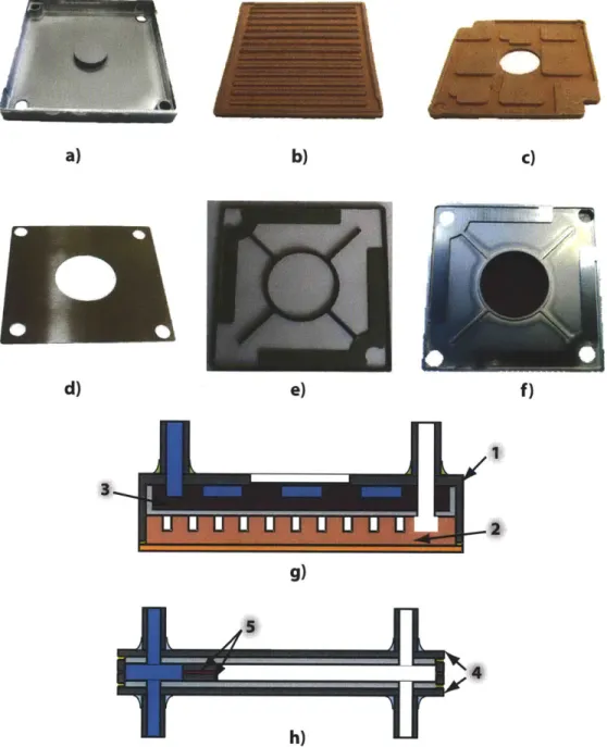
The first step in the manufacturing of the evaporator is the machining of the Monel frame. This frame is shown in Figure 1.2a. Copper is sintered in graphite molds that create the vapor and liquid channels in the copper wick. These parts are called 'molded parts' since they are sintered first in a graphite mold and then sintered again inside the Monel frame. The vapor and liquid channels molded parts are shown in Figure 1.2b and 1.2c, respectively. This and all of the sintering and brazing process involved in the manufacturing of PHUMP are performed under a protective
atmo-sphere of 4% hydrogen, 96% nitrogen.
Due to manufacturing constrains, the sinter structure is built into the Monel frame starting from the fluid side. The first step is the attachment of the liquid channel wicking structure into the Monel frame. A fine layer of 10 pm copper powder be-tween the molded part and the frame is used to bond these parts. A Monel powder layer is placed on top of the molded part. This Monel layer is sintered to create the thermally insulating layer. Then, the vapor channel molded part is placed on top of the sintered Monel layer and attached to the rest of the system with a thin layer of 10 pm copper powder between the Monel insulating wick and the molded part.
A second sintering process is used here to bond the multiple layers of the internal
structure of the evaporator. Then, the solid copper lid (which will be the base of the complete evaporator) is attached by sintering another thin layer of 10 prm cop-per powder between the vapor channel molded part and the copcop-per lid. Finally, the copper plate and the Monel frame are sealed using Tungsten Inert Gas (TIG) welding.
Figure 1.2g shows a labeled schematic cross-sectional view of the finished evap-orator. The Monel frame and the fine and coarse copper wicks are identified in the drawing.
Condenser Manufacturing
The condenser frame plates and the 'subcooling inserts' are chemically etched from a 0.020" thick sheet of Monel. The frame plates and the subcooling inserts are shown in Figure 1.2d and 1.2e, respectively. The attachment of these two parts is achieved
by means of silver brazing at 970 'C for 12 minutes. The result is a half condenser
frame as shown in Figure 1.2f.
The space between the subcooling area and the frame plate is filled with Monel powder. After this powder is sintered, two condenser halves are brazed together
us-ing a 0.002" thick 72% Ag, 28% Cu braze sheet cut to match the condenser profile. Brazing occurs at 720 'C for 12 minutes.
Figure 1.2h shows a schematic cross-sectional view of the finished condenser. The condenser frame plate and the subcooling insert are labeled in this figure.
Integration of PHUMP
The condensers are aligned in a jig and 0.375" ID rings of a 60% Ag, 30% Cu, 10% Sn braze alloy are placed around each of the vapor and liquid line joints (eight per condenser). Then, the vapor and liquid lines are slid through each condenser. This setup is heated to 740 'C for 12 minutes to melt the brazing alloy. This stack of condensers is placed on top of the evaporator and brazed to it at 320 'C for 12 minutes with a 80% Au, 20% Sn brazing alloy. Once the heat pipe is filled with degassed, distilled water, the heat pipe is sealed using a crimping tool. Finally, the impellers are attached as discussed in the work by Allison [2].
1.4
Literature Review
Several authors have measured the permeability, maximum capillary pressure and/or thermal conductivity of sintered metal wicks. Singh et al. [53] described many simple experimental methods to measure permeability, capillary pressure and thermal con-ductivity of water-saturated copper and polyethylene wicks. The principles of their experimental methodology are the same as the ones used in the present work and described in Chapter 2. Semenic et al. [52] measured the same properties for copper wicks with particle diameters in the ranges of 52-63 pm, 63-75 pm, 63-90 Pm, 75-90 pm and 90-106 pm. The maximum capillary pressure they measured was found to be linear (with negative slope) with average particle size. The particle size range with the smallest particles, 52-63 pm, had a measured maximum capillary pressure of 12 kPa, while the largest particles, 90-106 pm, had an 8.5 kPa maximum capillary
a)
b)
e)
f)
I
g)
h)
Figure 1.2: a) Machined Monel frame for the evaporator. b) Vapor channel molded part (10 pm copper powder). c) Liquid channel molded part (38-75 pm copper powder). d) Condenser frame plate. e) Subcooling insert of the condenser. f) Half of a condenser frame after silver brazing. g) Schematic cross-sectional view of the finished evaporator. The point labeled '1' shows the Monel frame (a), '2' shows the fine copper molded part (b), and '3' shows the coarse copper molded part (c). h) Schematic cross-sectional view of the finished condenser. The point labeled '4' shows the Monel frame plates (d), '5' shows the subcooling inserts (e).
pressure. Similarly, water permeability of the samples was found to be a linear func-tion (with positive slope) of the average particle size, ranging from 1.5 x 10⁻¹² M2
for the smallest particles, down to 2.4 x 101 m2 for the largest particles. Thermal conductivity of all the samples was very similar with an average of 142±3 W/m-K. The authors do not discuss the sintering parameters of fabrication of their samples.
Thermal conductivity of porous material has been an active area of research since the late 1800s. Peterson et al. [44] presented a summary of diverse expressions pro-posed to calculate the thermal conductivity of a porous material based on its poros-ity. Then, they compared these expressions with experimental values of their own and showed that all of the existing models are valid only in a very limited range of porosities. More recently, Atabaki et al. [5] performed a similar literature survey of expressions, finding the same problem as Peterson et al. Birnboim et al. [8] pro-posed a model based on two touching spheres as a unit cell used to predict thermal conductivity of a porous material. The authors assumed that the unit cell thermal conductivity is that of unit cell. Dan et al. [13], Devpura et al. [16], Ganapathy et al. [20] and Kanuparti et al. [25, 26], included the spatial connections between the high conductivity component imbedded in a low conductivity component by generating a random network of thermal resistors and then solving for its thermal conductivity. A similar model is used in this thesis and is described in Chapter 4.
Several authors [28, 56, 60] have studied the coalescence of two spherical particles (or a group of spheres) by surface diffusion, grain boundary diffusion and/or a com-bination of these mechanism. Missiaen [36] reviewed some of the major contributions to the modeling of sintering. Some authors have shown that, despite the many sim-plifications of the two-particle model, its predictions are fairly close to more complete and thus complicated models [28, 56]. The two-sphere model is described in Chapter
1.5
Thesis Overview
This thesis focuses on the properties of the sintered wick inside the heat pipe described above. Chapter 2 describes the sintering process followed for the diverse wicks consid-ered in this work. Additionally, the methodology of the measurements and the values of thermal conductivity, water permeability and maximum capillary pressure mea-sured are presented in this chapter. Chapter 3 explains the fundamental principles of sintering, applies them to the two-sphere model and relates the values calculated for the neck size and shrinkage with the experimental measurements. Chapter 4 explains the model developed for thermal conductivity, including the unit cell approach and its inclusion in a 3D random thermal resistor network. The results of this model are compared to the experimentally measured thermal conductivities. Conclusions of this thesis are presented in Chapter 5.
Chapter 2
Experimental Measurements
This chapter shows the results of measurements performed on copper and Monel 400 sintered wicks. Shrinkage, thermal conductivity, permeability and capillary pressure are the properties measured as a function of the wick's particle size, sintering time and temperature. First, the process followed to prepare the sintered wick samples is presented. Then, the methodology followed to measure each property is discussed. The results of these measurements are presented and discussed. Additionally, the effect of multiple sintering procedures on the wick's properties is investigated. Finally, a test designed to assess the robustness of PHUMP when subjected to extreme storage temperatures is described and its results are discussed.
2.1
Sample Preparation
2.1.1
Powder Material and Particle Size
As mentioned in Chapter 1, copper and Monel were the materials selected for the sintered wicks in PHUMP. A fine powder was selected for the sections of the sys-tem where high capillary pressure was required and a large particle size was used elsewhere to control the liquid-vapor interface and thermal conductivity without in-ducing significant pressure drops. Given its lower thermal conductivity, Monel 400 was used instead of copper where a layer of thermal insulation was required. Copper
Table 2.1: Chemical composition of the metal powders Comp
Chemical Copper 10 pm Copper 38-106
Cu Balance Balance Ni 0.002 -Ag 0.002 -C 0.006 -Fe 0.002 (max) -02 0.52 0.05 (max) Si 0.003 -Zn 0.002 (max) -Al 0.001 (max) -Pb 0.002 (max) -Sn 0.002 (max) -Mn
osition
[%]
Monel -33 pm tm (spherical) 30-40 Balance Monel -44 pm (non-spherical) 28 Balance 0.5 (max) 0.5 (max)was used whenever an isothermal section was desired in the heat pipe. A summary of the compositions of the powders used in this work is shown in Table 2.1. The copper powder was supplied by Alfa Aesar [1], while the Monel was bought from Sandvik Osprey [33]. These powders were confirmed to be spherical using a scanning electron microscope. Non-spherical Monel powder was used in the multiple sintering procedure tests. This powder was supplied by Atlantic Equipment Engineers [17].
Three different particle size ranges were selected for each metal and sieved from the powder batches shown in Table 2.1. For copper, 10 pm, 38-75 pum and 75-106 pm were the ranges considered. For Monel, the size ranges were -22 /m, 22-33 Im and -33 /m. Following the convention used for mesh sizes, a '-' in front of a number means that every particle below that particle size is included in the range.
Figure 2.1: Picture of copper and Monel disk and tube samples.
2.1.2
Sintering Procedure
Two different types of samples were prepared. For the thermal conductivity tests, metal powder was poured into a graphite mold. The graphite mold contained right-circular cylindrical cavities 2.5 mm deep and 12.3 mm, 14.3 mm or 15.8 mm in diameter. These dimensions were selected to match the size of the sample holders of the laser flash machine used to measure thermal conductivity. For permeability and capillary pressure tests, powder was sintered inside 4.5 mm ID tubes. The height of the sintered plugs inside the tubes was approximately 30 mm. The samples were shaken for 5 minutes using an electric shaker table. The material of the tubes and the sinter was the same. Figure 2.1 shows examples of some of the samples prepared.
After the samples were prepared, they were loaded in a tube furnace. A Lindberg-Blue [32], 1.5 m long, 15 cm OD tube furnace was used to sinter the samples. To avoid oxidation of the samples a protective atmosphere was used during sintering. First, pure nitrogen was used to purge the furnace tube. The nitrogen was allowed to flow for at least 1.5 hours. This purge time allows some of the oxygen to diffuse out of the pores between powder particles. Once the nitrogen purging was finished, nitrogen flow was stopped and then forming gas was used as the protective atmosphere. The composition of forming gas used is 4% hydrogen, 96% nitrogen. At the same time that the forming gas flow was started, the sintering process was started.
(U
600*~C/h Peak 4
a) temperature
Time
Figure 2.2: Time-temperature plot of the sintering process. All the samples were heated at 600 'C/h to reach the peak sintering temperature. The samples stayed at the peak temperature for different periods of time. The cooling of the samples followed the cooling of the furnace.
Figure 2.2 shows a time-temperature plot of the sintering process followed in this work. First, a heating ramp rate of 600 'C/h was used to reach the peak sintering temperature. The peak sintering temperatures were varied, with values of 450 'C,
550 0C, 650 0C, 750 'C, 850 'C and 950 'C. Depending on the specifics of the test run,
the furnace was held at the peak sintering temperature for different periods of time (referred as 'sintering time' in Figure 2.2). These periods were 0 minutes (cooling of the sample started as soon as the furnace reached the peak temperature), 15 min-utes, 45 minmin-utes, 90 minutes and 180 minutes. Once sintering was finished, the sinter was cooled inside the furnace, while maintaining the flow of forming gas. When the furnace reached a temperature bellow 200 'C, the forming gas flow was stopped and switched back to pure nitrogen. Nitrogen flow was stopped once the sinter reached room temperature. Figure 2.3 shows the temperature profile of the furnace as it cools. In this thesis both the heating and cooling processes are included in the analysis, so a distinction is made between the overall sintering process (which includes the heating and cooling time) and the isothermal sintering process, which is the time that the samples spent at the peak temperature.
900 - Data - Least-squares fit 750 -~ 600-c 450- T =289exp (-8 x 10 + 619 exp (-9 x10⁵)t o. E I-- 300- 150-0 100 200 300 400 500 600 Time [min]
Figure 2.3: Temperature profile of the furnace as it cools. Equation of the least-squares fit for the furnace temperature, T, as a function of time, t, is also shown. Data points were taken using the same gas flow rates used to fabricate all the samples. Copper 10 p-tm powder sintered for all peak temperatures and hold times considered in this thesis. 'Sintered' means that particles bonded together with enough strength to keep the shape of the wick even when gently tapped with a finger. Copper 38-75 pum and copper 75-106 tm samples held their shape only when the sintering temperature was above 650 'C. Even at this temperature, for hold times less than 45 minutes, some particles detached from the rest of the wick when gently tapped. Although thermophysical property results are shown for these samples, it is recommended that these size ranges are sintered at 750 'C or above. Spherical Monel powder sintered with structural rigidity at a minimum temperature of 850 'C and hold time of 90 minutes. However, non-spherical Monel first sintered at 820 'C for 15 minutes.
2.2
Geometric Measurements
Densification is an important characteristic of sintered objects. Densification refers to the reduction in the size and number of pores in a sintered object. As the number
and size of pores in a sintered wick decreases, its size also decreases. The change in dimensions of the disk samples due to sintering was measured and used to calculate the linear shrinkage and the porosity of the samples. The results of these measurements are shown in Figure 2.4 and Figure 2.5. Figure 2.4 shows the linear shrinkage (as a percentage) of the sintered disks as a function of holding time and peak temperature. Linear shrinkage was measured as the change in the diameter of the sintered disk samples as
AD
= (2.1)
Do
where c is the linear shrinkage of a sample; Do is the diameter of the sample before sintering (the diameter of the sample at room temperature); and, AD is the change in its diameter after sintering (measured at room temperature). A Tresna [57] caliper was used to measure the diameter of the samples. The uncertainty of the measured shrinkage was estimated at ±1.0%. It is important to mention that in this work, shrinkage is measured based on the diameter of the sample at room temperature. As the sample is heated to the peak sintering temperature, both the graphite mold and the metal powder will expand. However, the thermal expansion coefficient of the graphite mold is lower than the thermal expansion of either copper or Monel. Thus, the mold limits the expansion of the sintering powder. This effect and its impact on the measurements of shrinkage measurements performed in this thesis are discussed in the next section. This effect is accounted for in the error bars in Figure 2.4. For this reason, the error bars at the higher temperatures (650 'C and above) are asymmetric.
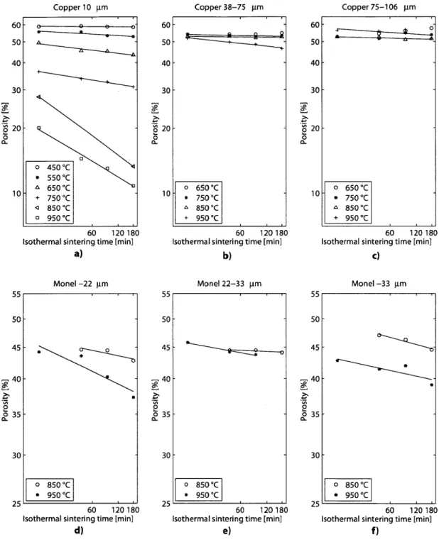
Figure 2.5 shows the porosity (as a percentage) of the sintered disks as a function of holding time and peak temperature. The porosity of the samples is calculated as
#
- Pwick (2.2)Pmaterial
where
#
is the porosity of a sample; Pwick is the density of the sintered sample; and,Pmaterial is the mass of the non-porous metal. The density of the porous sample was
Copper 38-75 m
60 120180 Isothermal sintering time [min]
a) 25.3 20.3 15.3 10.3 6.4- 5.4-4.4 S2.4 -o 650*C * 750 C A 850*C 1.4. + 950 *C 60 120180 Isothermal sintering time [min]
Monel -20 lam Monel 20-33 jim Monel -33 pm
60 120180 Isothermal sintering time [min]
d)
1.9 -
~t0
1.4
60 120180 Isothermal sintering time [min]
e) 4.7 3.7 2.7 (u 1.7 0.7 60 120180 Isothermal sintering time [min]
f)
Figure 2.4: Sample densification expressed as linear shrinkage of the diameter of the sample for a) copper 10 pm, b) copper 38-75 pm, c) copper 75-106 pm, d) Monel -22 pm, e) Monel 22-33 pm, and f) Monel -33 pm sintered wicks. The effect of the mismatch between the thermal expansion of the graphite mold and the metal powders is shown as asymmetric error bars. Detail about this effect can be found in the next section of this work.
o 650*C
* 750*C
A 850*C
+ 950 *C
60 120180 Isothermal sintering time [min]
c) 5.9 4.9 3.9 2.9 1.9 C0 S0.9 Copper 10 gm Copper 75-106 pm T
was measured using a Sartorius [49] digital weighting balance. The uncertainty of the measured porosity was estimated at ±1.0%.
As expected, the higher the sintering temperature and the longer the sintering time, the larger the shrinkage of a sample. It can also be seen that at low temper-atures the samples shrank rapidly, but the rate of densification decreased at higher temperatures. The fact that the data points follow a linear trend in a log-log plot con-firms the characteristic power-law behavior of densification as a function of sintering time [18]. A similar trend was obtained for the porosity of the samples. Nevertheless, porosity did not change appreciably for 38-75 pm and 75-106 prm copper samples at
650 'C and 750 'C, which could be attributed to the fact that these were the
temper-atures where the samples were barely sintered to keep their shape. At these relatively low sintering temperatures, changes in shrinkage were too small to be discernible.
In the case of the tube samples, the metal powder bonds to itself as well as to the tube wall. The bonds between the wall and the sinter inhibited shrinkage of the samples for the lower peak sintering temperatures. When the sintering temperature was large enough, separation of the wick from the pipe walls happened in some lo-cations. This was the case for the copper 10 pm samples, where separation occurred when sintered at 650 'C or above. Separation began as early as 820 'C in some of the Monel samples. Taking into account this separation is important when selecting a sintering procedure, because a gap between the wick and its container larger than the largest continuous pore in the sinter will decrease the maximum capillary pressure the wick can sustain. Figure 2.6 shows an example of a gap between the tube wall and the sinter observed under an optical microscope.
2.2.1
Effect of Graphite Mold on Shrinkage Measurements
For this work shrinkage was measured for a powder that is constrained by a graphite mold as it sinters. The mold has a lower thermal expansion coefficient than either
Copper 75-106 pam 60 50 40 30 2 20 0 10 60 120180 Isothermal sintering time [min]
a) Monel -22 jm 55 50-45 -- 40-* 0 850*OC * 950*OC 60 120180 Isothermal sintering time [min]
d) 60 50 40 30 0 20 0 a. 60 120180 Isothermal sintering time [min]
b) Monel 22-33 ptm
o 850*C
* 950 C
60 120180 Isothermal sintering time [min]
e)
60 120180 Isothermal sintering time [min]
c) Monel -33 gm 50F -* o 850 C * 950*C 60 120180 Isothermal sintering time [min]
f)
Figure 2.5: Sample densification expressed as porosity for a) copper 10 pm; b) copper
38-75 pm; c) copper 75-106 pm; d) Monel -22 pm; e) Monel 22-33 pm; and, f) Monel -33 pm samples.
Figure 2.6: Separation of non-spherical Monel sintered wick from the wall of a Monel tube. The sample was sintered at 820 'C for 15 minutes.
copper or Monel. Thus, as the temperature increases, the mold limits the expansion of the sintering powder. The thermal expansion of graphite is anisotropic, with a coefficient of 7.5 x 10⁻⁷ C-1 parallel to the grain and 2.7 x 10⁻⁵ 'C-1 perpendicular
to the grain [58]. Based on the minimum thermal expansion coefficient, the change in the diameter of the 15.8 mm mold is approximately 10 pzm when heated to 950
'C. This change in dimension is less than the uncertainty of the measurement of the
diameter of the samples, which is approximately ±0.04 mm. Thus, within the uncer-tainty of the measurement, the graphite mold does not expand during the sintering of the samples. Therefore, the metal particles of the samples are constrained by the graphite mold and may rearrange to accommodate the thermal expansion of the metal. Assuming that the particles can freely rearrange themselves to accommodate for the difference in the thermal expansion until the peak temperature is reached, and neglecting the shrinkage derived from sintering, the resulting samples would have a smaller diameter at room temperature after the sintering process, because their diameter at the higher temperature is smaller than the diameter of a sinter that is not constrained by the mold. Table 2.2 gives the calculated results for the starting diameter (i.e. an effective diameter) of an unconstrained copper sample that would result in the same final diameter as a constrained sample, assuming both constrained and unconstrained samples are subject to the same thermal history. In generating Table 2.2 the thermal expansion coefficients of the copper sinters are assumed to be the same as that of solid copper.
Table 2.2: Effective room temperature diameter of sinter after rearrangement due to graphite mold constraints
Peak sintering Actual starting diameter of Effective diameter at temperature sinter at room temperature room temperature due to
rearrangement 450 0C 15.8 mm 15.69 mm 550 0C 15.8 mm 15.66 mm 650 0C 15.8 mm 15.64 mm 750 0C 15.8 mm 15.61 mm 850 0C 15.8 mm 15.59 mm 950 0C 15.8 mm 15.56 mm
At the lower sintering temperatures (all of the 450 'C and 550 0C samples, as well
as the samples sintered at 650 0C for 0 and 15 minutes) the change in diameter due
to thermal expansion effects is on par with the measured shrinkage. Thus, at low temperatures, this effect could account for much of the measured shrinkages. At 450
0C, the shrinkage due to this thermal expansion effect is 0.7%, compared to the
mea-sured shrinkages that are all below 0.4%. A similar situation is found at 550 'C and at 650 0 for sintering times of 0 minutes and 15 minutes. In these cases, the shrinkage
expected due to thermal expansion is larger than the shrinkage measured based on the diameter of the mold. This behavior suggests that the effect of thermal expan-sion is overestimated. As the sintering temperature increases, the effect of shrinkage due to sintering becomes more important, thus the effect of shrinkage due to thermal expansion effects becomes smaller than the shrinkage derived from sintering. The difference between the shrinkage calculated assuming the initial diameter is that of the graphite mold at room temperature, and the shrinkage calculated assuming that the initial diameter is the effective diameter shown in Table 2.2 is at most 10%. Using the diameter of the mold instead of the diameter of Table 2.2 results in a systematic overestimation of the shrinkage.