A CASE Strategy Proposal for the
Traffic Manager Workbench Project
by
Timothy Chien
Submitted to the Department of Electrical Engineering and
Computer Science in partial fulfillment of the requirements
for the degree of Master of Engineering
at the
MASSACHUSETTS INSTITUTE OF TECHNOLOGY
May 14,
© Timothy Chien, 1999.
1999
All Rights Reserved.
The author hereby grants to MIT permission to reproduce and
distrib-ute publicly paper and electronic copies of this document in whole or
in part, and to grants others the right to do so.
A uthor ...
- ...
-
... ...
Department of Electrical Engineering and Computer Science
May 14, 1999
Certified by ...
DAmAr Gupta
Co-Director, Productivity from Information Technology
MUI loan School of Management
A ccepted by ...
---.----Arthur C. Smith
Chairman, Department Commitee on Graduate Thesis
Department of Electrical Engineering and Computer Science
A CASE Strategy Proposal for the Traffic Manager Workbench Project
by
Timothy Chien
Submitted to the Department of Electrical Engineering and Computer Science on May 14, 1999, in partial fulfillment of the requirements for
the degree of Master of Engineering
Abstract
With information technology (IT) permeating virtually every facet of society today, effec-tive management of the design, implementation, and delivery of these systems has become a top priority. To handle these projects, various methodologies, collectively known as Computer Aided Software Engineering (CASE), have been adopted at numerous IT and software application companies. A well-designed CASE plan can provide long-term return on investment, accelerating development and drastically reducing maintenance costs. Though the specific implementations of CASE vary widely, code analysis/genera-tion tools are typically used in conjuncanalysis/genera-tion with formally defined processes. This thesis proposes an overall CASE strategy for the Traffic Manager Workbench (TMWb), a suite of air traffic management applications used by the Federal Aviation Administration
(FAA), and gives examples of representative CASE components. The report concludes
with an analysis of the results from the study and a number of recommendations for con-tinued maintenance of the project.
Thesis Supervisor: Dr. Amar Gupta
Title: Co-Director, Productivity from Information Technology (PROFIT) Initiative, MIT Sloan School of Management
Acknowledgements
The author would like to thank a number of people for their gracious support in this research. Dr. Amar Gupta, Co-Director of PROFIT, and Rick Oiesen, ETMS Project Leader at
NVTSC, provided the author with the opportunity, guidance, and assistantship funding through
four academic semesters. Without them, none of this would have been possible. The author would also like to acknowledge the members of the TSD Development Team -- Mary Todd, Gene
Rusu, Charles Koutalidis, Yefim Keselman, Joe Zirpolo, Victor Rivkin, Jerry Stankiewcz, Angela Ge, Ruth Anthony, and Mary Costello. They truly made working at NVTSC a great experience.
The author would also like to thank the members of the Christian Students Association for their continual encouragement and prayers. Last, and definitely not least, the author expresses his deepest gratitudes to his family, who has perservered with him through thick and thin, providing unwavering support and inspiration for so many years. Thank you!
Table of Contents
1 Introduction ... 6
1.1 The Bane of Software Engineering...6
1.2 Historical Perspective.. ... 7
2 Object-Oriented Tools ... 10
2.1 The Bane of Software Engineering... 10
2.2 Notations Primer ... 10
3 CASE Processes... 18
3.1 Tool Integration Strategies ... 18
3.2 Motivation for CASE... 19
4 Air Traffic Management ... 21
4.1 Components of a Modem Air Traffic Management System ... 21
4.2 The Federal Aviation Administration ... 21
4.3 U.S. Air Traffic Control... 22
4 .4 E T M S ... 2 3 4.5 Traffic Manager Workbench (TMWb)... 26
4.6 Traffic Situation Display (TSD)...26
4.7 Rationale for CASE... 31
5 CASE Strategy for the TMWb ... 33
5.1 Problem Investigation ... 33
5.2 Existing High-Level Software Engineering Processes... 33
5.3 Reverse Engineering ... 38
5.4 Object Model...42
5.5 Recommended CASE Plan ... 45
5.5.1 Investigate "pain" in software development process ... 46
5.5.2 Assess CASE technology and organization's response...46
5.5.3 Prepare for transition ... 48
5.5.4 Solidify CASE vision... 50
5.5.5 Pilot CASE tools/methodology...50
5.5.6 Rolling out CASE...51
5.6 Design of Technical Resource ... 51
5.7 TMWb Tutorial...54
5.8 Benefits of Proposed and Completed Work ... 54
6 The Future of TMWb and CASE...56
6.1 Enhancements to the TSD ... 56
6.2 Future of CASE Technology ... 59
Appendices Appendix A Appendix B Appendix C Appendix D Appendix E
Survey of CASE Tool Vendors Use Case Diagrams
Collaboration Diagrams Class Diagram
Chapter 1
Introduction
1.1 The Bane of Software Engineering
In this age of technological advancement, it is hard to imagine executing a complex project without a focused design and development process. Product design and delivery management is a well-studied field and cuts across numerous engineering disciplines. However, for many complex software engineering projects, there is, in fact, no formal process in place. Two aspects of the field are responsible for this oversight: availability
of equipment and the short time needed to ramp-up to a programming skill set.
With minimal software/hardware and the necessary training, one can start writing code almost immediately. Ironically, this aspect of software development is its greatest downfall -because the essential skills can be learned relatively quickly and equipment is plentiful, charging into a project is a natural tendency. Once this "straight-to-coding" attitude sets in and functional (but often noninteroperable) components materialize, the idea of spending time on an initial design framework falls by the wayside. Inevitably, this leads to malformed software and the time and cost needed to put the project back on track can run several times higher than the original estimates. In fact, it can cost "10 times more to fix a bug at any stage of the development cycle than it does to fix it during the previous stage." (Jones 1997) Additionally, the stress level of the entire team
A sampling of software cost statistics:
From (Lano 1994),
- Information technology costs are divided in the ratio 35 percent hardware and 65 per-cent software, with 80 perper-cent of software costs being maintenance and 20 perper-cent forward engineering.
- Cost of software maintenance (most of a $3.5 billion software budget in 1973) was one of the major motivations for the US Department of Defense in sponsoring the development of Ada.
- Maintenance costs are $30 billion per year in the USA alone. From (Oliver 1995),
- For every six systems put in operation, two are canceled. - On the average, 50% of all projects run over schedule.
- Seventy-five percent of all projects have partial or incorrect functionality. From (Flecher 1994),
- Thirty percent of typical development activities is rework.
The deployment of Computer Aided Software Engineering (CASE) in countering these effects is taking a larger percentage of the IT manager's time and effort today than ever before. With today's evolving technical needs, the importance of CASE cannot be overlooked.
1.2 Historical Perspective
CASE grew out of early commercial and government-sponsored efforts to develop
(ALS), Ada Integrated Environment (AIE), Software Life-Cycle Support Environment (SLCSE), and Boeing Automated Software Engineering (BASE) Environment. Each
model was organized around a central data repository and concentrated their support on source code editing, compiling, linking, and debugging aspects of the project. Tools such as translators, compilers, assemblers, macro processors, linkers and loaders were, in fact, the first CASE tools, "computer-based products aimed at supporting one or more
software engineering activities within a software development process." (Brown 1994) As tools matured to automate more tasks, they grew to cover program analysis; examples are editors, debuggers, and code analyzers. Once design methodologies began to
crystallize, CASE tools also adapted, encompassing functionality to manage the entire software life cycle; examples are source code control systems, bug tracking applications, and software model builders.
The number of software tool vendors increased dramatically during the first 10-15 years. In 1990, there were over 400 CASE tool vendors and the annual worldwide market was $4.8 billion. (Brown 1994) The promise of increased productivity and reduction of cost in software development, along with the dropping cost of PC equipment, drove customers to make significant investments in CASE technology. The long list of design notations includes, among others, structured analysis (SA), data flow diagrams (DFDs), functional decomposition, Object Modeling Technique (OMT), Booch, Use Case, Design Patterns, and more recently, Unified Modeling Language (UML). In the next three sections, CASE will be explored in detail and motivation for its use will be presented. The CASE concepts developed will be applied to a real-time, air traffic management
system currently employed by the Federal Aviation Administration (FAA). This work will be detailed in Chapter 5.
Chapter 2
Object-Oriented Tools
2.1 Introduction
An effective CASE strategy depends on two crucial elements: selection of tools and an integration strategy. An appropriate selection comes from an understanding of the "pain" in the software development process, a feasible integration plan, and a familiarity with the tool landscape. The wide variety of tools available span the entire software life cycle and can be separated according to their functionality and input/output requirements. Tools can be interactive in nature (e.g. a design method support tool) or non-interactive
(compiler). Some support activities early in the life cycle of a software project and others serve later in the life cycle. There are those that are specific to a particular life-cycle step (requirements tool) and those that are common across a number of life-cycle steps
(configuration management tool). (Brown 1994) Since a number of program support tools are already used for the target system in this report, only design and life-cycle tools will be considered for the proposed CASE strategy. A number of representative software tool
vendors and their offerings are given in Appendix A.
2.2 Notations Primer
To better familiarize the reader with CASE, a few of the most widely used notations are described below:
- Structured Analysis (SA)
The concept of structured analysis can be traced back to early work at IBM Laboratories in the early 1970s, and to the methodology published by Yourdon in
1989. (Oliver 1995) Yourdon SA is primarily a methodology for representation,
con-sisting of data/control flow diagrams. Decomposition can be applied to the lowest level and then transformed into a set of structure charts which define a calling tree among modules. In structured methodologies, there is a clear distinction between analysis and design models. An SA diagram is shown in Figure 1.
Iterate over all Tiers
Model Figure 1 Example SA Diagram (Oliver 1995)
Hatley and Pirbhai (H-P) added refinements in 1987 and expanded the descrip-tion of the structure to an architecture model. The H-P notadescrip-tion also incorporated components and hierarchical decomposition. (Oliver 1995)
- Object Modeling Technique (OMT)
Early notations tied themselves quite closely to a specific implementation lan-guage and migrating to other platforms/lanlan-guages was a significant endeavor. With the advent of object-oriented technology, object modeling (OM) became the most widely used technique to visualize the design of a piece of software.
OM differentiates itself from procedure and data flow based notations by con-ceptualizing the behavior of the system as objects (with their associated attributes and operations) operating on each other. In a formal process, these objects encom-pass both elements of behavior and the programming constructs themselves. Unlike traditional data models which drive database design, object models also drive class design. (Oliver 1995)
In 1989, James Rumbaugh formalized much of OM in his notation Object Modeling Technique (OMT). OMT follows the steps of assessing available informa-tion, creating a behavior model, and creating a "how" model similar to SA; the views and notations selected can contribute to development of code/database schema and also represent the behavior of real-time systems (Fig. 2).
Example: Rumbaugh Notation
- Classes & Objects anon
part of "'Object N anm M odel" A ttende nce Current Grade Atteni C a s Complete Assignment ( ourse(uu A)) Name='Object-Orinted Aaralysti" Number="N /A"
(S tue rutueui)) \z / t aernLFTTe))
N ame= 'Oeorze " N ame="L ee "
Attenierre=95% A ttendence=100%
Cuneit Grade= "B+" Current Grade="A+"
Figure 2 Example OMT (Rumbaugh) Model (Stafford 1998)1 oo
- Booch
Booch notation shows the existence of classes and their relationships in the logi-cal view of a system. (Stafford 1998) During analysis, class diagrams are used to indi-cate the common roles and responsibilities of the entities that provide the system's behavior. During design, class diagrams are used to capture the structure of the classes that form the system's architecture
In Booch's notation, an object has state, behavior, and identity; the structure and behavior of similar objects are defined in their common class. The terms "instance" and "object" are, in fact, interchangable. A class is a set of objects that share a com-mon structure and a comcom-mon behavior. (Fig. 3)
Example: Booch Notation
- Classes are part of"Class Diagram"
- Objects are part of "Obj ect Diagram"
N(J
-A LL7 d<o Cr:.L~ t2L=Cn S LL YS-= aa A LLc cec] ccc A LLC o ClESC<SEoplcLc A Eciao~m nica
%N- " %c m - " -"95% r L rrea Grnd - " A " A Lu decS - '010 %-6 - -\ C.= urEc N4 u =ber OO A :Ca ur A I )Nn=o=c-"OO A"
Figure 3 Example Booch Model (Stafford 1998)
- Use Case
Conceived by Ivar Jacobson, use case diagrams identify system interfaces, known as "actors" and their usages, or "use cases", of the system. (Stafford 1998) The use case describes a user-valued set of system functionality from the perspective of the user and details what the "system" must do, not what "internal components/objects" must do. (Fig. 4)
Use Case Diagram (Jacobson)
-
Identifies system interfaces ("Actors") and their desired usages ("Use
Cases") of the system
"interacts
E>ternal Student
"Actor"
"Use Case"
with
R egister forClass Take Class USe. A ttend ext a d s Take Class for Credit Glass extends Audit Class
-
"extends"
-
an specialized version of a more general use case
-
"uses"
-
breakdown of functionality for complexity or reuse reasons
Figure 4 Example Use Case Model (Stafford 1998)
-UML
In 1989, the plethora of design notations and disparity among them prompted noted methodologists Grady Booch, James Rumbaugh, and Ivar Jacobson to bring together each of their notations (Booch, OMT, and Use Case, respectively) and produce a single notation -- the Unified Modeling Language (UML). UML consists of several model views-- Use Case, interaction, sequence, class, component, and deployment diagrams. Examples of these diagrams are given in Appendices B-E. Design Patterns
A design pattern systematically names, motivates, and explains a general
design that addresses a recurring design problem in object-oriented systems (Gamma 1994). Design patterns were founded on the common sense idea that reusable tricks of the [software] trade can be harvested from past successful designs. Patterns are primarily composed of interfaces and objects and have four characteristics: pattern name, problem, solution, and consequences. The pattern name is an easy to remem-ber title which captures the essence of the pattern (e.g. observer, composite). The problem describes the domain in which to use the pattern and the typical conditions that must be satisfied. The solution gives a concise picture of what the elements of the pattern are and how they interact. This is often depicted in a structure diagram. Consequences are just that: the ramifications, compromises, and trade-offs to
con-sider when using this pattern. The structure diagram of an Observer pattern is given in Figure 5.
Subject Attach(Observer) Delach(Observer) Notfy()
o---ConcreteSubject Get State() s- - -SetState() sub ject Stateobservers
for all o in observers
W
- - o->Update() subject relurn subjectState Observer Update() ConcreteObserver pdae)
--obseiveState
observerState
S t eI
subjet-c>GelState()
Figure 5 Observer Design Pattern Structure (Gamma 1994)
Chapter 3
CASE Processes
3.1 Tool Integration Strategies
Since CASE can influence a project from the code details to the upper levels of process management, it is useful to distinguish these areas in formulating a CASE
strategy. The means by which the components of the CASE strategy are integrated is of paramount concern, even more so than the selection of methods and tools.
The following are representative integration strategies: Computer-aided sub-processes (CASPs)
(Rader 1995) suggests a method to bring together process-oriented and
technology-oriented approaches to software development using CASPs. Examples of process-oriented improvements are the capability maturity model (CMM) and ISO
9000 standards. The CMM prescribes specific kinds of software engineering tasks
according to a company's expertise and depth of involvement in software development.
ISO 9000 promotes the idea that improvements can be accurately measured once a
company is certified on a set of process standards. CASE tools function as improvements in technology in automating specific stages of development.
CASPs consist of process and technology elements organized around a number of criteria: software requirements analysis practice, relevant standards, commercial/off-the-shelf (COTS) and home-grown methods/tools, platform, inputs and outputs for the
- CASE and CORBA
Interest in the Common Object Request Broker Architecture (CORBA) has had a marked effect in the direction of CASE technology. (Wallnau 1995) gives an
evaluation of the pros and cons of the role of CORBA in the integration of CASE tools. As proposed by the Object Management Group (OMG), CORBA is the standard that realizes interoperability between independently developed applications across
heterogeneous networks of computers. What this means for CASE is that non-object oriented technologies, such as Remote Procedure Call (RPC), may need to be fitted into the CORBA scheme or replaced if widespread adoption occurs. (Wallnau 1995) gives benchmarks of message throughput, comparing CORBA to RPC.
The paper also makes a comparison in data integration and control integration possibilities in CORBA, since they are of prime importance in a CASE implementation. The authors contend that many of the characteristics of useful data integration (services for transactions, data modeling/management, versioning/integrity) cannot be found in CORBA. However, in control integration, CORBA could potentially be useful in providing a dynamic invocation interface (in which clients can string together service
requests on the fly). They conclude that the greatest benefit CORBA has to offer is standardization on a common service infrastructure which is currently lacking in CASE tools today.
3.2 Motivation for CASE
So how beneficial is CASE after the initial investment? This question cannot be easily quantified since the time horizon for such a large scale implementation could
development process, a preliminary investigation is almost certainly worth the time and effort. In several independent studies, CASE has shown to improve development productivity by 20-40% and the maintenance of the final product by 100% (Flecher
1994). The intangible benefits of CASE are also worth mentioning: boosting of team confidence, encouraging inter/intra-team talks, providing for efficient resource allocation, and for many, enhancing job satisfaction. Other attractions of CASE include
improvement of product quality, automating synchronization of documentation with evolving products, and assisting in the maintenance of existing software systems. CASE
can rectify a number of issues: (1) careless programming style, (2) lack of
documentation, (3) dearth of understanding by current staff, and (4) constraints on extensibility. It is clear that (3) is a direct result of (2) and (1) could be partially
responsible for (4). This dissertation will concentrate on formulating a CASE strategy in remedying (2), (3), and (4) for the target system and address the specific benefits from implementing a CASE strategy. The next chapter gives background on the target system domain -- air traffic management.
Chapter 4
Air Traffic Management
4.1 Components of a Modern Air Traffic Management System
Today's global economy is inextricably tied to the efficiency of air transportation. With a projected increase in air traffic of 3 to 5 percent over the next 15 years, prudent management of air space is becoming increasingly difficult. A modem air traffic manage-ment system is concerned with automation, telecommunications, navigation/landing, sur-veillance, weather, and maintenance/operations. The general objectives of air traffic control are to (1) guarantee safe separation between aircraft in the air, (2) assist in preven-tion of collisions between aircraft and between aircraft and obstrucpreven-tions, (3) expedite and maintain orderly flow of air traffic, (4) provide information useful for the safe and efficient conduct of flights, and (5) notify appropriate organizations regarding aircraft in need of aid. (Wortmann 1997)
4.2 The Federal Aviation Administration
The Federal Aviation Administration (FAA) is the U.S. governmental entity charged with regulating and monitoring use of the National Airspace System (NAS). To this end, an ongoing concern has been the effective management of nationwide air traffic flow and several efforts have been initiated to give air traffic controllers and severe weather specialists adequate information regarding the current state of the traffic load, areas of congestion, and regions of severe weather activity. (FAA 1998)
The FAA was formally established in 1967, and is responsible for spearheading avi-ation activities in six major areas:
- Safety Regulation
- Airspace and Air Traffic Management
- Air Navigation Facilities - Civil Aviation Abroad
" Commercial Space Transportation
- Research, Engineering, and Development
Under the Research, Engineering, and Development branch, much effort has been invested in the development of innovative air traffic management systems and tools. The Office of Air Traffic Systems Development (AUA) was established to look into these issues and administer the deployment of these applications.
Within AUA resides five groups targeting various aspects of air traffic systems: - En Route Flight Management
- Terminal Airspace Management
- Weather and Flight Service Systems - Oceanic Airspace Management - Air Traffic Management
4.3 U.S. Air Traffic Control
At the top of the U.S. air traffic management hierarchy is the Air Traffic Control Sys-tem Command Center (ATCSCC) which deals with the management of nationwide traffic problems and coordination/approval of actions taken by the distributed traffic management
facilities. (FAA 1998) Underneath, the Traffic Management Units (TMUs) at the 20 Air Route Traffic Command Centers (ARTCCs) are responsible for the management of traffic problems within the scope of the ARTCC. At the bottommost level, TMUs at the Termi-nal Radar Approach Control (TRACON) facilities manage problems specific to the termi-nal areas under their control.
In recent years, novel techniques in automation and collaboration have been devel-oped to expand the capabilities of air traffic management systems. The Enhanced Traffic Management System (ETMS) and Traffic Manager Workbench (TMWb) are present day examples of these remarkable innovations.
4.4 ETMS
The ETMS was initially designed to provide a means by which air traffic data from a variety of sources over disparate networks could be collected and processed in one central location. (VNTSC 1995) Since then, it has risen in scope, and is now aimed at becoming a complete air traffic management solution. It is currently operational at over 70 air traffic facilities in US, Canada, and the UK and consists of operational pieces of the Advanced Traffic Management System (ATMS) research effort: (VNTSC 1995)
- Development of the Aircraft Situation Display (ASD), a graphical user interface depicting live aircraft positions, weather information, and areas of high traffic demand.
- Development of the Alert Function, which offers projected traffic demands for user-selectable airports, sectors, and fixes and is shown through the ASD.
- Development of a traffic conflict resolution system that proposes alternative flight paths to relieve high demand areas.
- Development of a decision support mechanism that selects the best alternative in high demand situations.
- Development of an automated system to form and execute the composite instructions for the selected resolution.
The ETMS receives information from numerous sources. Airline schedules are fed from the Official Airline Guide (OAG). The system receives messages generated by NAS computers at the 20 ARTCCs in charge of airspace over the contiguous United States
(CONUS). In addition, live flight data is received from En Route Radar and the FAA
Ter-minal Radar, weather data from the National Weather Service (NWS), and estimated departure clearance times (EDCTs) for ground delay programs from the ATCSCC.
(VNTSC 1995)
ETMS keeps a history of the flight data throughout the NAS and when traffic demand
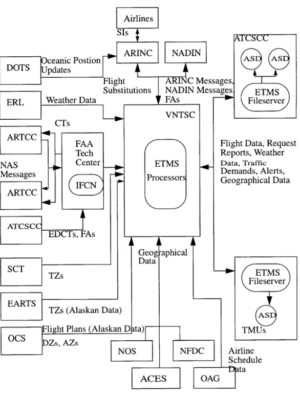
projections exceed alert thresholds (pre-defined traffic levels), a traffic management alert is sent to the ATCSCC, TMUs at the ARTCCs and TMUs at some TRACONs. A func-tional overview of the ETMS is given in Figure 6. (VNTSC 1997) As can be seen, there are various data paths; the VNTSC acts as the central broker for much of the incoming data and then dissmenates the information to the ARTCC, ATSCC, and TMUs for display on ASDs.
The ETMS was originally developed in Pascal for Apollo/Domain workstations and is currently being ported to C for the HP-UX platform.
ETMS
Fileserver
Flight Data, Request Reports, Weather Data, Traffic Demands, Alerts, Geographical Data ETMS Fileserver TMUs Airline Schedule
Fig. 6 ETMS Functional Overview (VNTSC 1995)
Postion
VNTSC
ETMS
Processors
4.5
Traffic Manager Workbench (TMWb)
The TMWb involves a reengineering of the user interface for the ETMS and consists of the Traffic Situation Display (TSD), Delay Manager, Autosend, List Server (Report Generator), and Electronic Mail. (Todd 1998) The List Server produces air traffic and weather reports in response to user requests. Electronic Mail allows users to communicate via private communication lines.
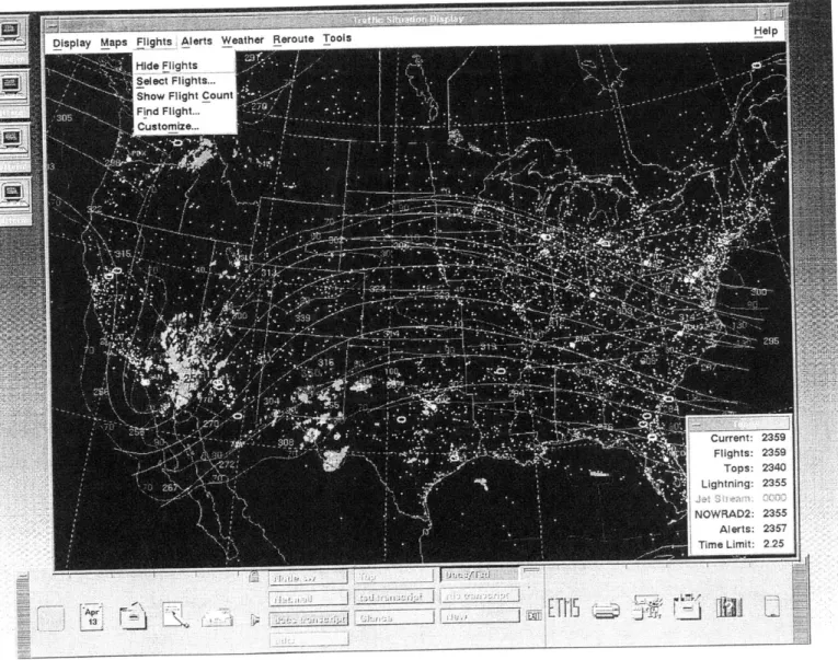
4.6 Traffic Situation Display (TSD)
The TSD can display a variety of data, including traffic load for elements of interest in the NAS (airports, fixes, sectors), map overlays (including geographic/ARTCC/TRACON boundaries, airways, fixes, navigational aids, airports, and SUAs), selected flights, and weather conditions. (Todd 1998)
The TSD's functionality is grouped under a number of pulldown menus. In addition, much of the functionality can be exercised via keyboard shortcuts.
-Under the Display menu, the user can adapt (or initialize) the TSD to a number of preset configurations (these configurations will be explained shortly). The user can also change the colors of various displayed elements on the fly (including map over-lays, foreground, and background colors). Through the Legend menu selection, the user can enter an arbitrary text message and have it displayed at the bottom of the
TSD.
- The Maps menu provides a number of functions associated with the maps database: - The Move/Zoom menu item allows the user to center the display on a specified
location at a given magnification scale.
- Find Map Item highlights a given element on the drawing area.
- The DME... menu item calculates distances between points designated by the user on the display.
" The Overlays function gives the user the ability to display any number of map
overlays (including airports, fixes, sectors, and navigational aids). A map overlay is a translucent layer on the drawing area consisting of specified map elements. - The Range Rings menu item allows the user to display an arbitrary number of
col-ored rings around a given element to measure various distances (in increments of 25, 50, and 100 miles)
- Projections allow the user to select from the following global viewpoints: Alaska, Atlantic, Canada, and Continental United States (CONUS).
- Runway Layout shows runway configurations for selected airports.
- The Alerts menu provides the following functions for monitoring alerted elements:
- Select Alerts lets the user select particular alerted elements (airports, fixes, sectors, or combinations) for display.
- Examine Alerts allows the user to monitor a TSD element's projected traffic load in increments of 15 minutes.
- Alarms allows the user to setup an element to flash or beep when alerted. - The Flights menu provides a broad range of functions in monitoring flights across
the United States:
- Show/Hide Flights causes the flights overlay to appear/disappear.
- Select Flights... gives the user a method to select particular flights for display, according to origin and/or destination. The user can also choose to toggle on/off the flight data block, the flight route and path.
- Show Flight Count show the current number of active and visible flights arriving/ departing from selected flights.
- Find Flight highlights particular flights on the display according to origin/destina-tion. Customize allows the user to customize all displayed flights to show/hide flight data blocks, origin/destination, route, path, and flight history.
- The Weather menu is responsible for controlling the weather display: - Show/Hide Weather toggles the weather overlay on/off.
- Select Weather lets the user select the type of weather to display and the appropri-ate color: 2km/8 km weather, radar tops, lightning, jet stream.
- Weather Report generates a weather report for a given airport.
- The user can show/hide, create, edit, and delete flight reroutes.
- The user may also choose to send the reroute information to another TSD user or
import an existing reroute.
- The user can initialize the TSD to a preset configuration by saving the state of spe-cific menu selections in an adaptation file. Upon restarting the TSD, the user can recall these settings with the Recall feature in the Adaptations submenu of the
Dis-play menu pulldown.
- The Tools menu contains a number of miscellaneous functions including: - Snapshot which allows the user to take a picture of the TSD in .xwd format.
- Network Utilities lets the user switch sites or reconnect to a hub site. - Replay allows the user to playback up to nine hours of historical TSD data. - Database Commands and EDCT Commands allows the user to send list server
requests more conveniently.
- Command Line Editor offers an easy way to execute many of the aforementioned functions through syntax.
- Script is used to define a series of commands that are run prior to TSD initializa-tion.
- Report Manager is used to list and display reports generated by list server requests.
The TSD has been recently ported from Pascal to C++ and makes extensive use of Motif/X.
4.7 Rationale for CASE
The TMWb was chosen as the candidate target application for the CASE strategy to meet the need for a formal development process. Several deficiencies were also gathered from site visits.
From a trip to the Albuquerqe ARTCC, 9/11/95-9/12/95 (Oiesen 1995):
- There was a problem with the alert count for ZAB65 sector, south and southwest of PHX (Phoenix). This was partially caused by the system's inability to handle ascent
and descent profiles for super-high sectors.
- Monitor Alert did not seem to recognize the third leg of military flight routes.
- Flights are missing on ASD that are present in PVD. - Flight plans are missing in ETMS due to parsing errors.
- Duplicate flights are shown on ASD.
- Monitor Alert doesn't work well when flights deviate around thunderstorm.
- Unreliable communication lines interfered with system performance. - There was a need for more extensive ETMS/TMWb training.
The TMWb would benefit from a solid CASE strategy, starting with reverse engineer-ing of the existengineer-ing code and developengineer-ing into an objectory process model that allows for controlled, iterative development and ultimately, forward engineering. This would allow developers to target problem areas quicker and provide for future enhancements. In the short term, the results of reverse engineering can be incorporated into a technical design resource.
Currently, the only documents available are the ETMS System Design Document,
ETMS Functionality Description, and TSD Users Guide which together offer an end-user
view of the ETMS and TSD. At present, there is no design documentation that maps sys-tem functionality to specific code modules. New developers on the project must rely on advice from experienced developers and wade through the code themselves, which can take several days to several weeks of effort.
An online design specification resource would allow new developers and users inter-ested in technical details to quickly come to an understanding of the system. The resource could also be easily extended and modified.
In the long term, the creation of a complete object model will allow developers to col-laborate seamlessly with a single notation. In addition, if the project moves to a different platform/language, the model can be used to automate code generation.
This thesis proposes a CASE strategy for the TMWb and then focuses on the design of a technical resource for staff members working on the TSD. The resource will detail UML object models, class specifications, and a tutorial for new developers on the project.
Chapter
5
CASE Strategy for the TMWb
5.1 Problem Investigation
The TMWb is composed of the Traffic Situation Display (TSD), Delay Manager, Autosend, List Server, and Electronic Mail. These applications provide the air traffic man-ager with the following broad capabilities:
" Identify regions of projected traffic congestion
- Identify areas of severe weather activity
" Track selected domestic flights
- Plan flight reroutes
- Request traffic capacity and weather reports
- Communicate with other TMWb users via private, communication lines
From conversations with the TMWb Project Manager and ETMS Project Lead, it was apparent that no formal CASE process exists for the TMWb. Both agreed that an investi-gation into the feasibility of a CASE process would be beneficial at this stage of the TMWb development schedule. The TSD was chosen as the initial target application since the source code for the TSD was readily available and the author was most familiar with its functionality.
5.2 Existing High-Level Software Engineering Processes
The DTS-56 Software Life Cycle Methodology (SLCM) is the current overall guide-line used for software development in the Automation Applications Division at the Volpe
Center ("DTS-56 Software ..",VNTSC 1997). The ETMS and TSD projects are both man-aged under these guidelines. The DTS-56 SLCM was developed from the Information Systems Development (ISD) Manual's Evolutionary Development Life Cycle (EDLC); the SPAS (Safety Performance Analysis System) II System Life Cycle Methodology; and the TMS (Traffic Management System) Development Cycle. The individual group manag-ers have discretion to tailor their specific project with the eight phases of the DTS-56
SLCM:
- System Requirements Analysis and Design
- Software Requirements Analysis - Software Design
- Software Development (and Unit Test) " System Integration and Test
- System Acceptance Test - Train, Install, and Evaluate
- Maintenance and Support
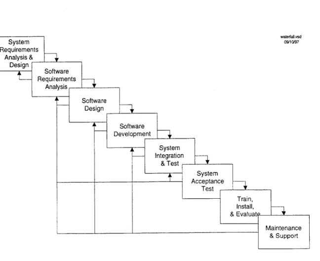
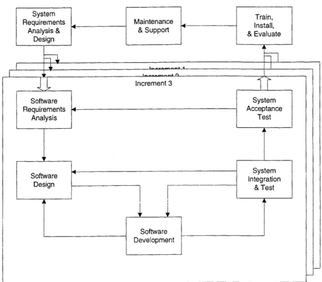
Common life cycle models correspond to specific workflows of these phases. These phases can map to the Waterfall Life Cycle, Incremental Life Cycle, and Evolutionary Model for Software Development. In the Waterfall Model, each phase progresses one by one, to post-deployment. In this model, system requirements must be determined at the start of the process, and reverting to an earlier phase is an exception. Operational function-ality is not assumed until the final phase. The Incremental Model follows the Waterfall Life Cycle, but provides for functional test of system components along each incremental phase. The Evolutionary Model expands the Incremental Model by allowing for iterative
development of the system requirements; this model assumes that the system requirements cannot be fully determined early in the process.
waterfailvsd 09/10/97
System Requirements Analysis & Design s increme2.vsd 1125197
The TSD is currently in the Maintenance and Support phase of the Evolutionary Model, having passed FAA acceptance trials in February and is being deployed at all ARTCCs in North America. All ARTCCs are expected to have operational TSDs by July
1999 and all TMUs are planned to be outfitted by the end of 1999.
The following CASE strategy work is part of the iteration workflow back to the Sys-tem Requirements and Design and is intended to improve the efficiency and organization of the Software Design phase. The objectives of this work were to (1) reverse engineer the major subsystems of the TSD, (2) create an object model that best captures the features of the subsystems, (3) formulate a detailed CASE strategy, (4) refine object models from the reverse engineering work for use in a comprehensive technical resource, and (5) design a tutorial for new developers on the TSD project. The models created for this work are to be viewed only as prototypes to demonstrate a component in the overall CASE strategy. Upon commencement of an actual CASE implementation, the models need to be sub-jected to rigorous, formal validation.
5.3
Reverse Engineering
Reverse engineering is the process by which source code is passed through an analysis
tool to produce a design specification. In the case of the TSD, a significant C++ code base on the HP-UX platform was already in place (-220 KLOC) and reverse engineering was chosen as a reasonable first step in creating rudimentary design models. In selecting an analysis tool, several tools were compared against a number of criteria -- ease of use, lan-guage/platform support, integration with existing process tools, price, and design notation support. This information is summarized in Appendix A. From the survey, Rational ROSE
Windows and Unix platforms, and supported UML 1.1 (a leading object modeling nota-tion). ROSE was priced comparable to other products ($2,000 per node-locked Windows license) and could also integrate with ClearCase, the source code control system currently used by the team. In addition, Rational had an existing customer base at the Volpe Center and could provide on-site training/support if necessary. It was decided that a PC would be purchased along with one ROSE 98 Windows license instead of a Unix license, which was
$6,000 per floating license. This would allow the team to limit their initial spending and
go with a different tool in the event of a poor evaluation.
Once the PC and ROSE 98 were purchased and setup, the next step was to move the
TSD source code from the ClearCase repository to the Windows environment. This was
accomplished by a colleague who set up a proxy on the Apollo domain to send files to a server on the Volpe Center LAN; the files could then be downloaded to the PC outfitted with ROSE 98.
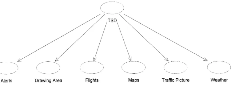
Because the ROSE C++ Analyzer only parses the class definitions from header files and the function headers from source files, noncompilable code can be passed through with no errors. Even so, the initial results from the analyzer were not promising and modi-fications needed to be made to the source code to get it more "ROSE friendly". These involved changing "#include" directives so that header file paths were resolved correctly (a Windows versus Unix difference) and correcting other miscellaneous style issues. After spending a few days on making these changes, the analyzer work progressed speedily. All of the subsystems were eventually parsed without error. A basic framework for the TSD was then mapped out (Fig. 11 & 12).
Flights Maps
Figure 11 Basic Framework of TSD
Weather Traffic Picture
Use Case name:
Alerts
Category: Use Case View
Documentation: AChart.[CH] Alerts.[CH] AlertsCharts.[CH] AlertFilters.[CH] AlertsSubSystem.[CH] AlertsSubSystemCmds.[CH] AlertsSubSystemFile.[CH] AlertsAlarmDialogBox.[CH] AlertsAlarmSetting Dialog Box. [CH]
AlertsChartsDialogBox.[CH] AlertsExamineDialogBox.[CH] AlertsExamineFlightsRequest.[CH] AlertsSelectDialogBox.[CH] AlertsTimelineDialogBox. [CH] AlertsTimelineDialogBoxCmds.[CH] AlertsTimelineTurnGreenDialogBox. [CH] AlertsTimeRange.[CH] AlertTimelineRequest.[CH] AlertTimelineRequestList.[CH]
5.4 Object Model
In constructing a prototype object model, a number of high-level Use Case diagrams were first generated (Fig. 13 and Appendix B). These diagrams depict all possible actions that the TSD user could take. Collaboration diagrams were created for each of the user actions (Fig. 14 and Appendix C). Each collaboration diagram shows the classes involved with the Use Case behavior and the function calls between them. Each call path is indi-cated with a link originating from the calling function and pointing to the class whose function is being called. If there is more than one method of initiating the behavior, each call path is labelled "A", "B", etc. Upon a test condition, each branch is labelled "1", "2", etc. The function being called is indicated by a note attached to the link.
<<extends
extends
Manage Delays Manage Routes
Use ETMS
«extends '
«extends>>
Send/Receive Electronic Mail
Figure 13 Use ETMS Use Case Diagram
A. Initiate request Al. request >2.25 hrs:
via Ul: SetStatus(; GetWidgetData() CreateTDBRequesto A2. request <= 2.25 hrs: Update() 2: Alerts ETMS User
Al. SendComm Al. SetSourcefor ParamsForGetData() TDBElement()
A2. GetAlertData() AlertTimeline RequestList
Al. Initialize()
A2. Update()
Figure 14 Request Timeline Extension Collaboration Diagram
6:
Since all the ROSE class elements were generated by the analyzer, the diagrams were easily created; each element can be expanded to list its operations, attributes, and hierar-chical/aggregate relationships (Fig. 15). In addition, the elements were automatically arranged into a class structure diagram by the analyzer (Fig. 16 and Appendix E). These were useful in identifying Motif widgets that are used for similar dialog boxes.
Class name:
DeleteAdaptFileSelectionOutlinerBox
Category: tsd
Documentation:
Extemal Documents:
Export Control: Public
Cardinality: n Hierarchy: Superclasses: DeleteFileOutlinerBox Public Uses: Widget String Protected Uses: Boolean Public Interface: Operations: className DeleteAdaptFileSelectionOutlinerBox Protected Interface: Operations: DeleteFile WidgetErrorChecking State machine: No Concurrency: Sequential Persistence: Transient
Figure 16 Inheritance Diagram for DeleteAdaptFileSelectionOutlinerBox class
5.5
Recommended CASE Plan
Because a CASE implementation is a substantial effort, careful consideration should be given to estimates of the time, cost, and needed resources. Each step is followed by a corresponding application to the TMWb. This workflow is based on an outline from (Flecher 1994).
5.5.1 Investigate "pain" in software development process Who? CASE initiative driver/support staff, technical leads What? Identify problem areas in software development process
The biggest obstacle in the TMWb software development process is the reliance on experienced developers for direction in making code modifications. There is a need for technical documentation that associates system functionality with the source code. A pre-liminary design of this resource is given in Section 5.6.
An additional problem is that the current bug tracking system is not integrated with the source code control system. Developers would gain from being able to link records of bug fixes with particular file modifications. Currently, the developer sends an email to the group upon a change to the main development branch. With integration of the bug tracking and source code control systems, these changes can be recorded along with the specific changes in behavior.
The lack of automated regression and GUI testing are also hindrances to the TMWb software process. With both in place, testing could be performed systematically and the
QA staff member's time could be spent formulating more complex test cases. This would
help identify new bugs in one subsystem caused by side effects from a bug fix to a differ-ent subsystem.
5.5.2 Assess CASE technology and organization's response Who? CASE initiative driver/support staff, technical staff
Aplication to the TMWb
A brief survey of tools was performed in the selection of a prototyping tool (Sect. 5.3
Reverse Engineering). Given that the TSD is a graphical interface for displaying real-time
ETMS data, tools that are commonly used for engineering environments were favored
over those developed exclusively for business application use. Since the system was devel-oped entirely on a Unix platform and the documentation produced in a Windows environ-ment, a suitable tool needed to be able to produce models usable across both platforms.
In an actual CASE process, a more rigorous search must be performed to get a repre-sentative cross section of the tool market. This would involve a more extensive literature search, and honing in on papers written on systems similar to the TMWb (e.g., Wortmann
1995). A tool feature-system need matrix could be developed to effectively communicate
the results of the investigation. These features should be associated with the development process, which could range from the code details to the system workflow . The team should consider how the development process will need to change to implement CASE methods. To gain hands-on experience, staff members can attend CASE conferences, ven-dor tool demonstrations, and even visit similar sized organizations with a CASE process in place.
The staff should move towards an agreeement of the most prominent features of tools/ methodologies and present their findings to the technical leads. After discussion among the technical leads and their staff, a "readiness" survey needs to be given to all developers, asking for feedback on how they perceive CASE affecting their current roles and responsi-bilities. The questions should address their specific areas of expertise within the project and how they feel CASE can/cannot provide benefit.
After collecting and reviewing responses, a list of pros/cons can be drawn and posed to the entire group. Any tools currently used that lend support to a CASE initiative should be concurrently reviewed. Once a final meeting to dicuss these points takes place, the CASE and technical leads need to make a decision to stop, postpone, or move ahead with a full or partial CASE effort. The leads may also choose to limit their plan to just one area they feel needs the most improvement.
5.5.3 Prepare for transition
Who? CASE initiative driver/support staff, technical leads, product managers
What? Assess sponsorship, delineate justification, create work plan, staff transition
team
Application to the TMWb
The transition work plan consists of the following sections:
Sponsorship assessment
An initial funding proposal for the project will assist in the rest of the work plan. The
CASE initiative driver, TMWb/ETMS project managers, and division directors will need
to meet to decide a fair apportionment of the costs. Current market prices for CASE soft-ware range from $2,000-$10,000 per license and for suitable PCs, $2,500-$4,000 per sys-tem. The group must consider whether outfitting several PCs with Windows-based tools is more cost effective than acquiring several Unix licenses which can cost $10,000+ per floating license. Another factor is the hiring of additional staff members to concentrate on
Progress metrics
Given that a typical CASE installation may not result in benefits for 1-5 years, the met-rics by which the progress of the CASE implementation and usage will be measured is
integral to the work plan and the return on investment. Some metrics to consider are
per-centage of development time spent fixing bugs, perper-centage of code/design reused, and
total number of bugs discovered at each stage of development.
Risk identification
Transitioning to a CASE project entails a number of risks; there can be extensive
tech-nical, business, and political hurdles. Of the three, the TMWb will be most impacted by
the technical challenges of setting up the CASE infrastructure and training staff members
on the tools. The current configuration management system, ClearCase, will allow for
integration with third party vendor tools. However, the tools may not provide the needed
functionality, so a careful analysis is needed to explore all options. The biggest political
challenge will be to push the acquisition approval through management and gain support
from division directors.
Transition strategies
The specific proposal for transition should take into account the speed of the
imple-mentation, whether a management or staff oriented approach should be taken, the depth of
analysis, the level of detail, and a set of specific milestones. Future enhancements to the
5.5.4 Solidify CASE vision
Who? CASE initiative driver, product managers
What? Prepare for environmental evaluations, administer surveys concerning
development/maintenance environment, project future application needs,
document CASE vision, assess organizational change Application to the TMWb
This stage of the CASE proposal is useful for a "cooling off' of the initial work plan draft. Feedback on the draft can be collected from the technical staff in the form of sur-veys, interviews, and discussion groups. The final draft should clearly describe and justify the CASE vision.
5.5.5 Pilot CASE tools/methodology
Who? CASE initiative driver/support staff, technical lead/staff, executive management What? Pilot selected tools, formulate a technical plan for deployment
Application to the TMWb
This stage is an extension of the initial research on the tool market space from Section
5.5.2. At this time, the CASE staff selects the team members who will be piloting the
pro-totype CASE tools. Those selected should be potential users of the system who have a fairly good understanding of the CASE vision draft. Prior experience with software pro-cess methodology/tools would also be helpful.
The pilot team is responsible for defining the tool criteria, getting price quotes, partici-pating in vendor demos, and developing pilot projects. A pilot project targets a section of a full CASE process (e.g. object modeling/design) and should exercise the relevant features
of the corresponding tool. The team should present the results for procurement and man-agement approval. Teammembers should also be ready to feedback to Section 5.5.1 if the product features do not fit the pilot project.
5.5.6 Rolling out CASE
Who? CASE initiative driver, technical lead/staff, product manager What? Execute, continually reexamine needs
Application to the TMWb
Once the pilot projects pass the team's evaluation, the final phase of the CASE strategy is to proceed with execution of the work plan. It is recommended that the team maintain a careful watch on the deadlines in other groups that are working in conjunction with the TMWb project. It would also be helpful to have evaluation breakpoints, so that the work performed up to date can be examined and the work plan adjusted accordingly. The team's experiences should be recorded in a log.
5.6 Design of Technical Resource
An online technical resource aims to fulfill the needs of the technical staff, giving them a bridge between the TSD User's Guide and the source code. The proposed framework is a set of hypertext documents. Sections in the TSD User's Guide can be linked with the rele-vant TSD subsystems and their object models. (Fig. 17) If the reader wants to drill down to specific code sections, an index to the file and lines in question can be retrieved and then matched to the actual file in ClearCase. This section will also list developers' comments on working with the specific code modules. In order to keep the functionality and code synchoronized, an annotation (e.g. "Alerts pickables made more sensitive") can be placed
by the developer once he/she has checked in the changes to the main development branch
corresponding to the functionality change. In addition, a number of keywords will accom-pany these changes (e.g. "Alerts pickables"). The keywords are used to best match search requests generated by the reader; he/she can also search through the list of annotated changes to find a previous feature request or bug fix. Developers' comments on functional-ity changes, grouped by subsystem, would also be available. In order to link the docu-ments to the source code, the browser needs to have read access to the ClearCase repository and be setup to identify element annotations on HTTP-CGI requests.
T, I C- I- L - I r -3 17I 71 f.: I I I (- -I I CI- I~~ .T' ~~ il rr ~r r ± i--i-I " 'tL-:3C-DialogBox Class name:
DeleteAdaptFileSelectionOutlinerBox
Category: Documentation: C Public n DeleteFileOutlinerBox Widget String Boolean className DeleteAdaptFileSelectionOutlinerBox DeleteFile WidgetErrorChecking External Documents: Export Control: Cardinality: Hierarchy: Superclasses: Public Uses: Protected Uses: Public Interface: Operations: Protected Interface: Operations: State machine: Concurrncy: Persistence: Sequential Transient No tsd5.7
TMWb 'utorial
With a basic technical guide in place, a hypertext-based tutorial can be constructed. Based on the author's experience in working with the TSD, the tutorial is proposed as follows:
Introduction
What is air traffic management? How do air traffic controllers use the TSD? Functionality Overview
Arrangement/description of subsystems and related source files
TSD Development Chronology
Functionality revisions cross-referenced with ClearCase element annotations Appendices
Example of setting up Emacs environment and ClearCase configuration specifica-tion
Example of checking out/in and merging file(s) to main development branch Example of labeling code version
Example of annotating changes and updating technical resource
5.8
Benefits of Proposed and Completed Work
The reverse engineering and object modeling work (Sect. 5.3 and 5.4) serve a number of purposes:
- They serve as proof-of-concept in showing that preparing the source code and setting up the applications for analysis and modeling can be done without much hassle.
- The ROSE objects generated by the analyzer can be maintained on a server and mul-tiple clients can modify/extend the models.
- The models can be used as part of ongoing internal documentation. With Rational
SODA, the UML models can be imported directly into MS Word documents.
The proposed work provides the following benefits:
- A CASE strategy streamlines the development process and allows developers to communicate on the design level -- before any heavy coding takes place.
- An automated regression/GUI testing application would allow the TMWb tester to devote his/her time to creating complex test scenarios.
- With integration of the bug tracking and source code control systems, the time to identify and resolve software defects is drastically reduced.
- The "knowledge ramp-up" time for a new developer will be greatly reduced with the use of the tutorial and technical resource.
- For experienced developers, the technical resource provides an easy way of correlat-ing a new defect with one that has been previously discovered and resolved.
Chapter 6
The Future of TMWb and CASE
6.1 Enhancements to the TSD
The following future enhancements to the TSD can benefit from the process investiga-tion:
- Redesign of Range Rings Dialog Box
The current Range Rings Dialog Box implementation (Fig. 16) will be redone to be similar to the Select Flights Dialog Box implementation. This will both reduce the complexity of code and also improve the user interface. With Rational ROSE, the reverse engineered models of the Select Flights Dialog Box can be used as a starting point for the new Range Rings Dialog Box. Skeleton code for the necessary user inter-face elements can be generated from the models.
- Redesign of Report Manager
The current implementation of the Report Manager (Fig. 17) allows the user to select and view requested list server reports from a separate dialog box. The FAA has requested a redesign of the Report Manager so that reports are listed as icons in a menu bar at the bottom of the main TSD window. Using the ROSE models for the Traffic Picture Subsystem, the main menu bar at the top of the TSD window can be used as a starting point for the redesign.
Select Range Ring: defaults Range Rings L Show 0I 0 OK
zIKI
abel Location No.
El BOS E DFW El DEN Apply Cancel Distance Color 50 100 50 Help
Figure 18 Select Range Rings Dialog Box
Figure 19 Report Manager
Report Manager Filter Reports
E]
l
0 Location Report Type Filter Reports Help Close DisplayDate/Time & Sequence No. Clear Filter File
I I