Business Process Improvement Using Axiomatic Design and
Object-Process Methodology
by
Jason M. Casebolt
J.D., Seattle University School of Law, 2010
B.S. Business Administration, The Ohio State University, 2003
Submitted to the Faculty in partial fulfillment of the requirements for the degree of Master of Science in Engineering and Management
at
Massachusetts Institute of Technology June 2016
2016 Jason M. Casebolt. All Rights Reserved.
The author hereby grants to MIT permission to reproduce
and to distribute publicly paper and electronic copies of this thesis document in whole or in part
in any medium now known or hereafter crqated.
A uth o r: ... MASSACHUSETTS INMG-tTE OF TECHNOLOGY
JUN 23
2016
LIBRARIES
ARCHIVES
Signature redacted...
Jason M. CaseboltSystem Design and Management Program
C ertified by:...
Signature redacted
May 6, 2016
Dov Dori
Thesis Supervisor Professor, Information Systems Engineering, )ch'on, Israel Institute of Technology
/~1) MI71%earfhiAfIi#e Accepted by: ...
Signature redacted.
Patrick Hale
Chairman & Senior Lecturer, Engineering Systems Division Director, System Design and Management Program
Jason M. Casebolt
ACKNOWLEDGEMENTS
To my family, colleagues, mentors, and supporters who were my sources of inspiration for my studies at MIT. . .
Family: First and foremost to my wife Leanne. Her encouragement and engagement with our son Jackson (who was born 2 weeks after beginning the program) enabled our family to function while I concentrated on MIT learning. Her patience and perseverance made earning this education truly a team-effort. To my parents, Mac and Dolores and their never-wavering support and encouragement that has enabled me to reach every goal I have ever set for myself To Ken Magness, who like my brother, looked after my wife and son during my trips to Boston.
Supporters: To insightful and supportive leaders, Lindsay Anderson (LGO, '93) and
Lisa Slagle, who supported my goal to learn better problem solving at MIT. To advocates Jose Garza, John Byrne, and Steve Patneaude (SDM, '06); as well as legal educators WH. ("Joe') Knight and Thomas Antkowiak, whose enthusiastic mentoring and encouragement enabled me to combine "legal thinking" with "systems thinking."
MIT Community: To the educators in the MIT System Design & Management program,
particularly Pat Hale, who welcomed me into MIT, and Dov Dori, who mentored me on both this thesis and Object-Process Methodology.
Cohort Teammates: To Chris Gardner, Kory Miller, David Parry, Eli Grun, Drew Hall,
and Andrew Walz whose support and wit made the most out of long hours of learning.
Believers: Finally, to Tyler Staal and Justin Franke, who both believed in me enough to push me farther than I had ever thought possible.
... I wouldn't have started or finished this journey without all of you.
Jason M. Casebolt 2
Business Process Improvement Using Axiomatic Design
and Object-Process Methodology
By
Jason M. Casebolt
Submitted to the System Design and Management Program on May 6, 2016 in Partial fulfillment of the Requirements for the Degree of Master of Science in Engineering and Management.
Abstract
This thesis introduces AD-OPM BPI, which is a new method of conducting business process improvement using both Axiomatic Design and Object-Process Methodology. The premise underlying the method is that modern process improvement techniques boast large efficiency gains, but fail to address the broader process system. Through first using Axiomatic Design to map and optimize the process system, broader-inefficiencies will be addressed before they constrain individual processes. Then Object-Process Methodology is conducted for process-specific optimization by utilizing modern system architecture layering principles to identify non-value-adding entities and improve them through deletion or simplification.
A case study at a large aerospace manufacturing company demonstrates the method in practical application. Results suggest that application is better suited to new or small-scale systems due to the challenge of applying Axiomatic Design to pre-existing large scale systems. Despite this limitation, Object-Process Methodology remains a viable option for business process improvement, whether or not it is coupled with Axiomatic Design in AD-OPM BPI.
Thesis Supervisor: Dov Dori
Title: Professor, Information Systems Engineering Technion, Israel Institute of Technology
MIT Research Affiliate
Jason M. Casebolt
Table of Contents
C hapter 1: Introduction ... 5
Chapter 2: Critique of the Current State of BPI...7
Chapter 3: Introduction to Axiomatic Design... 11
Chapter 4: System Analysis and Optimization with Axiomatic Design ... 12
Chapter 5: Introduction to Object-Process Methodology ... 21
Chapter 6: Process Analysis and Optimization with Object-Process Methodology ... 26
Chapter 7: AD-OPM BPI Case Study ... 30
Chapter 8: AD-OPM BPI Summary and Conclusions ... 62
Jason M. Casebolt
Chapter 1: Introduction
Emerging as a major focus in the 1980's and 1990's, Business Process Improvement ("BPI") has been a steady undertaking for major companies around the globe (Harrington 1991) (Harmon and Wolf 2014). The definition of BPI used here is simply "improvement of a process [by] means [of] changing a process to make it more effective, efficient, and adaptable" (Harrington 1991, 133). The leading drivers of this movement have been the need to save money and to improve performance. Additional motivations include increasing customer satisfaction, improving organizational responsiveness, complying with regulations, such as Sarbanes-Oxley, and major events, like a merger or an acquisition (Harmon and Wolf 2014). These efforts have made BPI a big business, with process improvement departments, consultants, and practitioners who focus a large part of their time or resources on improving business processes. They use popular products and methods, such as Lean, Six Sigma, Business Process Reengineering, Workflow, ERP software, and Business Process Management Suite software.
Despite over 20 years of focus, companies are still spending substantial sums on process improvement each year. For example, a 2013 survey of over 300 large companies revealed that 46% spent at least $500,000 that year on process improvement efforts (Ibid., 22). Nearly half of those companies (26% of the overall total) spent at least $1 million. Of all companies surveyed, 31% classified BPI as a major strategic commitment (Ibid., 12).
The purpose of this thesis is to apply "systems thinking" by using Model-Based Systems Engineering ("MBSE"), specifically Axiomatic Design ("AD") and Object Process Methodology ("OPM"), to perform a new method of BPI (collectively "AD-OPM BPI"). This approach treats a set of processes as a system to be engineered, and each individual process as a product to be architected with considerations for requirements, form, and function.
Jason M. Casebolt 5
The rest of this thesis is organized as follows: Chapter 2 presents a critique of the current state of BPI, to which this thesis addresses. Chapter 3 introduces AD. Chapter 4 describes the first part of the AD-OPM BPI method, where AD is used to perform system analysis and optimization. Chapter 5 introduces OPM. Chapter 6 describes the second part of the AD-OPM BPI method, where OPM is used to perform individual process analysis and optimization. Chapter 7 applies the AD-OPM BPI method on a real-life case study at a large manufacturing company. Chapter 8 summarizes the results and conclusions.
Jason M. Casebolt
Chapter 2: Critique of the Current State of BPI
Processes are a key aspect of contemporary systems engineering ("SE") theory and practice; however, SE theory and practice are currently not key aspects of process design or improvement. "While many have tried to settle the debate by providing process modeling standards and tools, most of them have fallen short in important areas, particularly when it comes to treating processes as systems and using SE approach in their development"
(Browning, Fricke and Negele 2006, 105). Processes alone are not systems-systems comprise objects transformed by processes. Processes do not happen in vacuum-they transform objects within context of a system, and this is where value is created. Neglecting objects in a process model is a major cause of the inadequacy of the process model techniques and the reason why they fall short of providing good process improvement tools. Neglecting a systems-of-systems approach, that combines objects with the processes to be improved, is contrary to the gains that are being targeted with all of the resources being allocated to the field.
Linkage Does Not Demonstrate Conscious System Design
Consistent with foregoing a SE approach, current practices to demonstrate process compliance result in clear linkages between related processes to reveal structure (Damelio 2011). Structure is expressed by objects, which are things that exist. This is in contrast to processes, which are things that occur. While structure can be demonstrated and verified, best practices do not yield an architecture that demonstrates a conscious design, or even purpose, of the process system. Even the term "process system" is a misnomer as there is no system without the other objects that a process transforms, creates, consumes or changes the state of.
The difference between the two concepts of existing linkage and preferred architecture is that linkage only shows relationships "that give systems their added value," while system architecture reveals the "interfaces among activities" that reflect the conscious design of the
Jason M. Casebolt 7
system (Browning, Fricke and Negele 2006, 109).
Examples of current practices that prioritize linkage over architecture are process trees (types of relationship maps) and compliance matrices that are popular methods to demonstrate compliance (Damelio 2011) (Page 2000). Simple examples of each are provided in Figures 2.1 and 2.2 respectively. Though each have different formats, both methods convey the simple relationships between the processes involved. Other than connectivity, neither process trees nor compliance matrices provide a clear demonstration of the design of the system, context of the requirements of the process system, waste beyond requirements that is present within the system, or demonstration that architecture satisfies the intended function.
Procedure
A
Process 2
Process 3
Figure 2. 1: Simple Process Tree
Jason M. Casebolt MIT SDM Thesis
8
0
Policy
Procedure
Process
Procedure-1
Policy-1
Procedure-3
Process-2
Procedure-5
Figure 2.2: Simple Process Tree
Focus is on the Scope of a Process Instead of the Scope of the System
Another critique of modern process improvement methods is that the focus is on single or a limited set of processes. This often occurs through Lean, Six Sigma, or other process mapping methods that select individual processes, or process groups, for which there is a concern (LeanOhio). By only reviewing individual processes and without reviewing the broader system, higher-tier design decisions that constrain lower-tier processes are also not examined (Suh 1998). This means that higher-tier system constraints will continue to constrain the lower-tiers. Therefore, while methods focused on individual processes may yield up to 50% or more efficiency improvement, the broader system remains unaddressed, incrementally improved, and sub-optimal until the higher-tier system design decisions are addressed.
Mapping Methods Are Too Vague to be Effective
Another critique of the current state of process improvement is that popular mapping approaches are not really effective for optimizing a system of processes. This seems like a contradiction given the objective results that routinely are part of such improvement efforts (LeanOhio). But there are aspects that have "caused debates, misunderstandings, and wastes
Jason M. Casebolt 9
MIT SDM Thesis
of time and money in industry, not to mention a failure to realize the advantages provided by a really useful process modef' (Browning, Fricke and Negele 2006, 109-110). The distinction is
that models provided system and process context, where other modern methods simply do not. Ironically, detailed process models with enough system context to be useful are disfavored by some companies. This is due, in part, to an incentive for companies "to keep the
models purposefully ambiguous so that when a process conformance auditor shows up, any actions by the workforce will in high likelihood be found to fall under the large and loose umbrella of a vague process description" (Ibid.). Therefore, many companies consciously or
unconsciously tradeoff better understanding of business processes rather than risk exposing auditors to a visualization of the complexity of their process system.
Critique Summary
Processes will continue to be a source of inefficiency for companies as long as the systems that comprise them are ignored. Without considering the conscious design and scope of the system, process improvement efforts remain too localized to be effective on a larger scale. As current practices of process improvement bifurcate efficiency increases to lower tiers, companies are incentivized to embraced ambiguity at the higher-tier levels to obscure the design rather than risk audit findings that could be associated with poorly demonstrating the system due to excessive-complexity of a process model. To address this tension, the AD-OPM BPI method is presented as a means to optimize both the process system and individual processes, while increasing audit compliance by clearly demonstrating how the process design choices clearly fulfill process system requirements.
Jason M. Casebolt 10
Chapter 3: Introduction to Axiomatic Design
Axiomatic Design ("AD") is a general systems design methodology developed by Professor Nam P. Suh. This method of design embodies the nature of engineering, as it
"consists of synthesis and analysis, which mutually reinforce each other in a feedback loop"
(Suh 2001, xv). While there are many possible synthesis tools, Axiomatic Design enables the
"application of scientific principles and rigorous mathematical tools" to demonstrate that a
certain system design is "good" without having to rely purely on a subjective opinion (Ibid.). This method bases the design of system architecture on hierarchical maps that comprise, amongst other inputs, Functional Requirements ("FRs") and Design Parameters ("DPs") (Suh 1998). The goal of these maps is to analyze the decisions that are made in a design and demonstrate how the FRs and DPs map to each other. This FR-to-DP mapping is then compared to design axioms, theorems, and corollaries that respectively demonstrate the "fundamental truths" of good design, inferences that are made from axioms, and concepts that can be proven through mathematical argument (Ibid., 205). To the extent that axioms, theorems, and corollaries demonstrate that the design can be improved, then a redesign using AD will be more consistent with those concepts and will reveal either a "good design" if the redesign satisfies the axioms, or a "better' or "best" design if the redesign remedies
inefficiencies consistent with the theorems and corollaries (Ibid., 207-209).
Jason M. Casebolt 11
Chapter 4: System Analysis and Optimization with Axiomatic Design
The process of performing Axiomatic Design involves four steps: (i) defining the FRs of the system, (ii) mapping between the domains, (iii) evaluating the independence of system functions, and (iv) evaluating the information content to validate "best design" (Ibid., 191-193).
In what follows, these steps are discussed in depth.
Step I - Define the FRs of the System
The FRs are the "minimum set of independent requirements that completely characterize
the functional needs of the product [or other system] in the functional domain. By definition, each FR is independent of every other one at the time the FRs are established' (Ibid., 205). In
the context of traditional engineering, FRs represent the Customer Needs ("CNs") or attributes that must be satisfied by the system. Concurrently, the Constraints ("Cs") are also identified, as the fulfillment of the CNs in the functional domain will be shaped by the presence of Cs. The FRs are formed in a solution-neutral manner, meaning that they should not be written with any particular solution in mind so that designers can creatively find multiple ways of fulfilling the FRs (Ibid.). A solution-specific FR therefore becomes a C to the rest of the design, thus reinforcing the practice of resisting solution-specific concepts until absolutely necessary.
Step 2 - Mapping Between the Domains
After the FRs are identified in Step 1, the corresponding DPs must be mapped. This mapping links the requirements of the system onto the physical or otherwise functional domain that manifests it (Ibid., 191). DPs are chosen through creativity, but are bounded by the need to satisfy FRs and limited by the presence of Cs. Similarly, each DP that is created becomes a constraint to each subsequent tier of progressive design that flows from within it.
Jason M. Casebolt 12
D11
J R I 1 1
I .~ I : 2R 2 ) E A , P I L I P2 2 )
FR I I E-R 12 I DI 1 D111 1 1
Shad o~ed haxes rieroleaf
Figure 4.1: Concept of Axiomatic Design (Suh 1998, 195)
Mapping can take several forms, both graphically and mathematically, but the thought process behind it remains constant. The example in Figure 4.1 shows the relationships of a one-for-one FR-to-DP design. As the solution-neutral FR becomes more defined, so does the design embodied by the DPs. This continues to the subsequent tiers of requirements and design, until the "leaves" are represented. The "leaves" are displayed with bold outline, where each "leaf' indicates an "FR that does not need further decomposition" (Ibid., 195). DP "leaves"
satisfy respective FRs, and a higher-tier FR or DP is satisfied by combining the respective
"leaves" that tier off from it.
To transition from the top-tier FR-DP concept to the lower-tier FR-DP leaves requires a technique called "zig-zagging." Professor Suh "observed that when you reason about a system,
you alternate reasoning in the form domain and the function domain. One tends to start in one
Jason M. Casebolt 13
domain and work as long as practical, and then switch to the othe" (Crawley, Cameron and
Selva 2015, 44). Applied here in Figure 4.2, each level of DPs constrains the tiers of FRs and
DPs that satisfy it. For example, "zig-zagging" occurs when as much of the Tier-1 DP has been defined, and to define any further requires "zig-zagging" to the FR domain to define the Tier-2 requirements, from which the respective Tier-2 DP's can be designed. This repeats through each tier, with the FRs and DPs starting as solution-neutral and then becoming more narrowly constrained at each interval until the design becomes solution-specific "leaves."
Figure 4.2: "Zig Zagging" Concept (Adapted from Suh 2001, 30)
Jason M. Casebolt MIT SDM Thesis
14
1)PI21 P DPIl 'om
E; P r '
I unri'oIntI2
-W
Step 3 - Evaluating the Independence of System Functions
Axiom 1: The Independence Axiom
Maintain the independence of the Functional Requirements (FRs)
The third step of applying Axiomatic Design is to evaluate the DPs and FRs against Axiom 1: The Independence Axiom. The Independence Axiom is satisfied when either (i) "each
of the FRs can be satisfied independently by means of one DP," or (ii) FRs are not satisfied
independently by means of one DP, but independence is still achieved "if the DPs are changed
in the proper sequence" (Suh 1998, 192). The former is referred to as an uncoupled design and
the latter represents a decoupled design, both of which are desired by designers. All other designs are considered coupled designs, which violate the Independence Axiom and are
undesirable to designers.
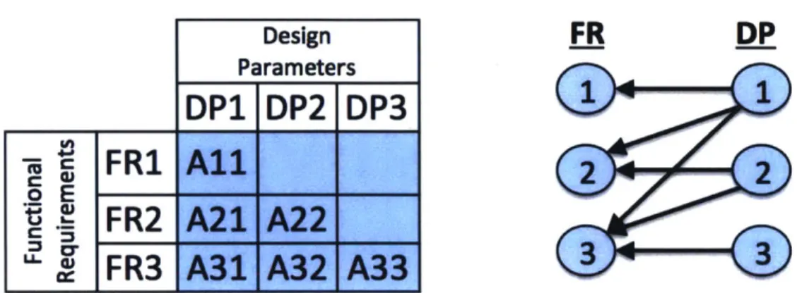
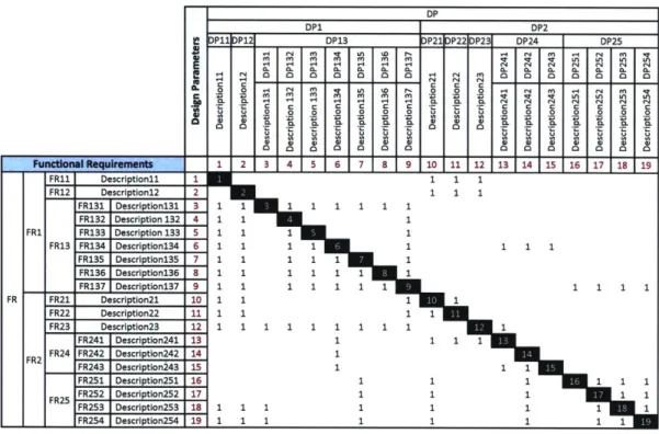
An uncoupled design results in a design matrix where the relationship of FRs to DPs is one-one, and where the requirements for independent sub-function can be satisfied by any
sequence in the design. Another term for this is a diagonal design matrix, where the
relationships are represented only on the matrix's diagonal (Ibid.). Examples of an uncoupled design concept and matrix are provided in Figures 4.3 and 4.4.
Design
FR
DP
ParametersDP1
DP2jDP3
.A
-4.
FRI
All
P WFR2
__A22_ _ '~FR3A3Figure 4.3: Uncoupled Design Concept (Adapted from \V
Jason M. Casebolt MIT SDM Thesis
an Eikema Hommes 2015)
15
-I DP DP1 DP2 DP11IDP121 DP13 IDP21DP22jDP23 DP24 DP25 0 0 1-4 CN r14 O r-CO I 0n M I 0n I 0 0 02 C0 0 0 0 0. 0O 02 0 04 0 0 0n C0 a a . o- o 0 C 04 0T 0 0 01 0n 04 0l 0o 0 0 Functional Requirements 1 2 3 4 51 6 17 18 1 9 10 11 112 113 114 15 16 17 1T8 19 FRI1 Description11 1 FR12 Descriptionl2 2 FR131 Description131 3 FR132 Description 132 4 FRI FR133 Description 133 5 FR13 FR134 Description134 6 FR135 Description135 7 FR136 Description136 8 FR137 Description137 9 FR FR21 Description2l 10 FR22 Description22 11 FR23 Description23 12 FR241 Description241 13 FR24 FR242 Description242 14 FR2 FR243 Description243 15 FR251 Description252 16 FR252 Description252 17 FR5FR253 Description253 18 FR254 Description254 19
Figure 4.4: Uncoupled Design Matrix (Adapted from Suh 2001, 282-283)
A decoupled design results in a design matrix where the relationship of FRs to DPs is more than one-for-one, but where independent sub-function still occurs when a proper sequence enables the DPs to satisfy the FRs in a manner similar to a diagonal design matrix. This can also be referred to as a lower triangular design matrix, where several FR-to-DP associations occur only on the diagonal and in the lower-left of the matrix (Suh 1998). Here, the absence of associations in the upper-right of the matrix indicates that sequencing of the remaining DPs that fall on or under the diagonal will fulfill the FRs in a manner as functionally effectively as a matrix that contains only diagonal inputs. Examples of a decoupled design
concept and matrix are provided in Figures 4.5 and 4.6.
Jason M. Casebolt MIT SDM Thesis E .V CA 0 .2
i
16 IlaDesign Parameters
DP1
DP2 DP3
FR1 All
o E. '
FR2 A21 A22
C
FA
. JFR3 A31IA32 A33
FR
DP
2
2
3
3
Figure 4.5: Decoupled Design Concept (Adapted from Van Eikema Hommes 2015)
E EU DP DP1 DP2 DPIP121 DP13 IDP21IDP22[DP231 DP24 I DP25 0 01 M rn rn rn MA rn or 1 o o o .2 0L 0 0 0 '4 0 0 N-rn 0, 0u 0 0u 0 0n 0 o o 1-i 0 0 Functional Requirements 1 2 3 4 5 6 7 8 9 110 111 112 13 14 15 16 FR11 Description11 1 FR12 Description12 2 FR131 Descriptionl3l 3 1 1 FR132 Description 132 4 1 1 FRI FR133 Description 133 5 1 1 1 FR13 FR134 Description134 6 1 1 1 1 FR135 Description135 7 1 1 1 1 1 FR136 Description136 8 1 1 1 1 1 1 FR137 Description137 9 1 1 1 1 1 1 1 FR FR21 Description2l 10 1 1 FR22 Description22 11 1 1 FR23 Description23 12 1 1 1 1 1 1 1 FR241 Description241 13 1 1 1 1 FR24 FR242 Description242 14 1 FR2 FR243 Description243 15 1 1 1 FR251 Description251 16 1 1 1 FR252 Description252 17 1 1 1 FR25 FR253 Description253 18 1 1 1 1 1 1 1 FR254 Description254 19 1 1 1 1 1 1 1 -q ., L 0 N 0 0 (Y. 0
Figure 4.6: Decoupled Design Matrix (Adapted from Suh 2001, 282-283)
Jason M. Casebolt MIT SDM Thesis .LI on -z 0 0 M V) r-4 C 0 ..p 2 U Q) 0 0 17 -r I fr"i
Finally, a coupled design matrix results where there are several FR to DP relationships that cannot be sequenced in manner that enables independent function. This is represented by a design matrix with associations that exist on both lower triangular and upper triangular sections, regardless of the sequence they are arranged (Suh 1998). This results in sub-functions that cannot be performed independently. Examples of a coupled design concept and
matrix are provided in Figures 4.7 and 4.8.
Design Parameters
DP1I
DP2 DP3
o E C a)0 LLWFR1 All A12 A13
FR2 A21
A22 A14
FR3 A31
A32 A33
FR
DP
11
22
Figure 4.7: Coupled Design Concept (Adapted from Van Eikema Hommes 2015)
I I DP E 0a DPI I DP2 DP1lDP121 DP13 IDP21IDP22IDP231 DP24 I DP25 c2 0 0 0 0L 0 0 0 0 0 0-0D C0 0 r.2 C 04 M C14 r 0 U 0L 04 0-0 It 04 0n C0 0-0n 0 0 0: 0n Functional Requirements 1 2 3 4 5 6 7 8 9 10 11 12 13 14115 16 17 18 19 FRIL Description1l 1 1 FR12 Description12 2 1 FR131 Descriptionl3l 3 1 1 1 1 1 1 1 1 FR132 Description 132 4 1 1 1 FR1 FR133 Description 133 5 1 1 1 1 FR13 FR134 Description134 6 1 1 1 1 1 FR135 Description135 7 1 1 1 1 1 1 FR136 Description136 8 1 1 1 1 1 1 1 FR137 Description137 9 1 1 1 1 1 1 1 FR FR21 Description2l 10 1 1 1 FR22 Description22 11 1 1 1 FR23 Description23 12 1 1 1 1 1 1 1 1 1 FR241 Description241 13 1 FR2 FR24 FR242 Description242 14 1 FR243 Description243 15 1 FR251 Description251 16 1 FR25 FR252 Description252 17 1 FR253 Description253 18 1 1 1 1 FR254 Description254 19 1 1 1 1 1
Figure 4.8: Coupled Design Matrix (Adapted from Suh 2001, 282-283)
Jason M. Casebolt
Step 4 -Validating Information Content for "Best Design"
Axiom 2: The Information Axiom
Minimize the information content of the design
The second Axiom is the Information Axiom, which states that the information content of the design should be minimized. Professor Suh expands on this by noting that "among all the
designs that satisfy the Independence Axiom, the design that has the least information content is the best design" (Suh 1998, 192). With this premise, the uncoupled or decoupled designs
that satisfy Axiom 1: The Independence Axiom are considered "good" designs. Between them, the "best" design is the one that minimizes the information content.
Functional Requirements FR11 FR12 Description12 FR131 Descriptionl3l FR132 Description 132_ FR133 Description 133 FR13 FR134 Description134 FR135 Description135 FR136 Description136 FR137 Descriptionl37 FR21 Description2l FR22 Description22 FR23 Description23 FR241 Description241 FR24 FR242 Description242 FR243 Description243 FR25 FR251 FR252 FR253 FR254 Description251 Description252 Description253 Descriotion254 DP DP1 DP2 DP11 DP12 DP13 DP21 DP22 DP23 DP24 DP25 - N (n V) LA WA ( N N ( ( N ( o M M m M (N ' T LA LA VA L 31 4 5 8 91 0 11 12 1 4 5 16 17 1 41 1~ r 4 0. 2p0 0 0p 0 0 0 0 0 0 0 5 Not " d"dsg C C CL C C C C C ~U U 0 0 0 0 0 U U 0 U 3 567 91 11 112 13 14 15 16 17 18 1:H9' 9 10 11 12 13 14 U , 15
16 Lower Triangle = Decoupled Design 17 "Good" design
18
19
Figure 4.9: Visualization of "Good" Designs
Jason M. Casebolt MIT SDM Thesis Description11 FR FR1 FR2 19
The example in Figure 4.9 summarizes what Axiomatic Design characteristics are considered "good". Here, an undesired design is any design that has FR-DP coupling apparent in the upper triangle. Desired designs are those where FR-DP linkages appear purely on the diagonal and/or lower triangular values. It is between all designs that map to the diagonal or lower triangle values from which the information content will be evaluated to determine the best design.
The information content involved is "simply the information needed to satisfy the highest
functional requirements" (Ibid., 192-193). This information content is presented in the context of
the logarithmic probability of satisfying the functional requirements. For application of AD-OPM BPI presented in this thesis, the actual logarithmic computation is not necessary.
Summary
AD is useful for analyzing a system and demonstrating how its design fulfills its requirements. Through mapping the maturation from a solution-neutral concept through the design decisions that result in a solution-specific design, AD demonstrates more than just what a design is, but also answers the questions of how and why the design is made. Beyond more context, the combination of AD mapping and the two design axioms provides an opportunity to objectively define the characteristics of "good design", thereby highlighting a desired state to target through process system redesign efforts.
Jason M. Casebolt 20
Chapter 5: Introduction to Object-Process Methodology
OPM is a leading MBSE platform due, in part, to its December 15, 2015 release by the International Organization for Standardization ("ISO") as the ISO-19450 specification for "Automation Systems and Integration - Object-Process Methodology" (Dori 2002) (International Standards Organization 2015c). Founded on the minimal ontology of stateful objects and processes that transform them as a set of necessary and sufficient building blocks, OPM is a holistic conceptual modeling language and cross-system lifecycle methodology, expressed graphically in a single kind of diagram and a complementary, auto-generated natural language text. It is different from other MBSE modeling languages in (i) the equal priority given to stateful objects and processes as the only two conceptual building blocks needed to represent systems in any domain - the minimal ontology, and (ii) the bimodal representation of the OPM model in both formal intuitive graphics and automatically generated text - simples sentences in a subset of English.
OPM is flexible in its application and has been applied in a wide array of industrial domains, from defense and avionics through electronic consumer appliances to software engineering, Web applications design, and molecular biology. OPM has been used in the evaluation of complex socio-technical system in fields such as aerospace, defense, information systems, medicine, sciences, and space exploration (Mordecai and Dori 2015). Formal yet
intuitive, OPM is learned quickly and enables involving the customer as a partner, starting from the early product or system development phases all the way to deployment and maintenance, providing for the integration of risk and interoperability into the architecture and design of complex systems and systems-of-systems.
Jason M. Casebolt 21
Using OPM to Create Models Models Repository Browser Business Process OPD Hierarchy Default Lmprved
(ZA General Example
Company ProcessPrcs Improving Management Department Improvement Method Method Axiomatic Design Object-Process Methodology
E Puine:c Frocess can be Default by default or yicrl
Default is initial. Improved is final.
Improvement method consists of On ect-Process rethoolg and omioatfc Design. Company is physical.
S Company consists of Process anagement Department. Process Manageent Department is physical.
Process Mvanagem-rent Department handles Process Improving
Process Improving requires limprovemrent Miethod
Process Improving changes Puziness Process from De,:,fauit to Imr
Things List
Templates PGnear
Testing C:3 0 c) A -A
Figure 5.1: OPM Model of AD-OPM BPI Method
Jason M. Casebolt 22
To use OPM, the freely available CASE tool OPCAT provides an environment that enables users to design OPM models, which are referred to as Object-Process Diagrams
("OPDs"). (Dori 2002) OPDs created in OPCAT automatically generate Object-Process
Language ("OPL") text in a separate panel, which is a textual description of the OPD in a subset of English. In addition to model creation, OPCAT enables model simulation through executing the model for behavior verification and validation (Ibid.). Figure 5.1 demonstrates the concept of this thesis through a simple OPM model of Process Improving using Axiomatic Design and
Object-Process Methodology that are both aggregated into an Improvement Method. This is
visualized through OPCAT's OPD (top) and OPL (bottom) views.
The Building Blocks
Visual
Representation Textual Form Definition Description
Nouns; capitalized first An object is a thing that
letter in every word; if has the potential of Static things. Can be
Object ending with "ing", stable, unconditional changed only by "Object" is placed as a physical or mental processes.
suffix existence.
U
Lz-I
Nouns in gerund form;
capitalized first letter in A process is a pattern of Dynamic things. Are Process(ing) every word; if not transformation that an recognizable by the
ending with "ing", object undergoes. changes they cause
"Process" is placed as a to objects.
suffix
States describe
Objet Nonsadjetive orobjects. They are
Object Noun, sadjectives or A state is a situation an attributes of objects.
I capitalized object can be at. Processes can
change an object's state.
Figure 5.2: OPM Entities (Dori 2002)
Within OPM, a system is comprised of physical (tangible) or informatical (intangible) things-objects and processes-that are represented by rectangles and ovals respectively (Dori 2002). A key premise of OPM is that objects and processes are of equal importance and complement each other for providing a complete structural and procedural specification of the system. Objects are things that exist in some state, and are represented by nouns. Processes,
Jason M. Casebolt 23
represented by verbs, preferably in their gerund form (ending with "ing"), are things that transform objects through creating or destroying objects, or changing object states.
The Four Fundamental Structural Relations
Shorthand Name Aggregation Exhibition Generalization Instantiation
Symbol
A
Relates a whole Relates an Relates a general Relates a class of Meaning to its parts exhibitor to its thing to its things to its
attributes specializations instances
Figure 5.3: OPM Structural Relation Symbols (Dori 2002)
To supplement the objects, processes, and states, OPM supports structural and procedural relations, expressed graphically as links, as well as hierarchical organization for complexity management. The four fundamental structural links, represented and defined in
Figure 5.3, are aggregation-participation, generalization-specialization, exhibition-characterization, and classification-instantiation.
Procedural Links
These links are generally used between an object and a process. They cannot be used to link objects together.
Link Name OPD OPLDescription
__________Symbol SentenceDecito
Processing Process uses object up Consumption consumes entirely during its
Object. occurrence.
Processing Process creates an entirely
Result Ojct yields Obect. new object during its
occurrence.
Processing Process changes the state
Effect Process Object affects of the object in an
Object. unspecified manner.
Object is a human that is
Object not changed by the
Agent Object Processi handles process; process needs the
Processing. agent object in order to occur.
Object is a non-human Processing that is not changed by the
Instrument Objectig requires process; process needs the
Object. instrument object in order
to occur. Figure 5.4: OPM Procedural Links (Dori 2002)
Jason M. Casebolt MIT SDM Thesis
While structural links connect objects to objects or processes to processes, procedural links connect processes to objects or to object states. Procedural links include transforming links (consumption, result, input-output, and effect), enabling links (agent and instrument), and control links (which are out of scope for this thesis). Consumption implies that the process consumes the object. Result links indicate that the process generates the object. An input-output link pair denotes that the process changes an object from an input state to an input-output state. The effect link denotes that the process changes the object without specifying the input and output states. These are demonstrated in Figure 5.4 (Ibid.).
Enabling links, also presented in Figure 5.4, denote objects that are needed for the process to occur but themselves are not transformed. The agent link expresses the fact that the agent (a human) enables the process. An instrument link denotes a non-human enabler.
As noted, beyond visualization, OPCAT generates OPL to evaluate the system through textual description in English (Ibid.). OPL has two purposes. First, it enables domain experts and systems architects to better analyze and design a system by providing a description-based model to validate or contrast their graphic-based OPD model. Second, OPL establishes a firm basis for automatically generating the designed application. An OPL example is displayed in the bottom portion of Figure 5.1.
OPM Summary
OPM is a dual approach that uses graphic-based modeling with text-based validation to construct a system. Through the freely available OPCAT software and the minimal number of selectable entities, OPM is easy to obtain, learn, and use. Despite its simplicity, it enables robust system exploration beyond architecture, including states, aggregation, and zooming within systems-of-systems. Its recent emergence as an international standard provides for its
use as a consistent method for the foreseeable future.
Jason M. Casebolt 25
Chapter 6: Process Analysis and Optimization with Object-Process
Methodology
To perform the OPM portion of the AD-OPM BPI method, the design of a business
process must be (i) decomposed, (ii) rationalized, and (iii) optimized. Modern systems
architectural principles provide a basis from which OPM can be used for these purposes (Crawley, Cameron and Selva 2015, 121-122). This thesis applies these modern systems architectural principles to optimization or improvement of business processes.
1. Decomposition
The first step is to decompose the design into its entities so that it can be evaluated. Using OPM, each entity of the design is identified as either an object or a process. The focus of the first step should be accuracy of the identification, not the relationships between the objects and processes; relationship association will take place in the next step.
2. Rationalization
The second step is to rationalize the entities that were identified in Step 1, namely, to express meaningful and useful relations among them. With OPM, this involves connecting the objects and processes that were identified with structural and procedural relations. Modern systems architecting provides the basis for this linkage (Ibid.).
---I ~~~ ood.. .. raM --- ~ett
---Operand Internal value Value related Supporting Supporting objects related process instrument processes and interfaces
object
Figure 6.1: OPM-Based Layered Systems Architecture (Cameron 2014)
The concept of layered architecting within OPM is the starting point of performing BPI on
Jason M. Casebolt 26
individual processes. Following this approach, the system's objects and processes are identified and separated into the operand object - the major object transformed by the system, value-related objects and processes, and finally supporting processes and objects (Ibid.). Figure 6.1 provides an example of this rationalization approach, resulting in a layered architecture. This approach rationalizes not just the relationships, but also the value-adding role that each object and process plays in the context of the system's intended function.
3. Optimization
After rationalization is complete, the AD-OPM BPI method takes a different point of view than the layered systems architecture approach proposed by Crawley et al. (Ibid.). Where Crawley et al. suggests that supporting objects and processes provide structure that enables the value-related objects and processes to perform their respective functions, the AD-OPM BPI method maintains that the supporting objects and processes serve as both waste and complexity to a process performance. The concept portrayed in Figure 6.2 proposes that the operand, as well as the value-related objects and processes, are considered to be value-adding and are therefore desired. The non-value-adding waste that exists as the supporting objects and processes should be minimized or eliminated to reduce the process as much as possible to fulfilling its intended function, and therefore increasing efficiency.
The concept underlying this view is that the additional layers of architecture in a business or industrial process serve to complicate, add time, and otherwise hinder a process to perform its pure function. This departs significantly from product development, where such additional structures serve to support the system by design. The key is properly identifying value-adding entities as those that if removed would degrade or otherwise prevent the intended function of the business process from occurring. The remaining entities-- those that do not meet this standard-are therefore considered non-value-adding.
Jason M. Casebolt 27
r- d p r- - --- - - - - - -n r n s I n- r
-poes I I &LP
VaI dadNnvlu de
propctrsste 2ondr
ig .2A -PMBI Vau ei itin(oiidf C aeo 04
O nrands nte ai value-ddnglandSnpn-iau-oding objects
and ro sse, tenae oprizonses ursthrughe n y pcebsates an nterfmare h
Va/ r naade. Nndval en
t n rav t mr pect ouary
wigur spe2:i typsP BPI Vpamlztue Deinton(odfidfrns.ern204
The nheon-iishv enrtoaie novalue-addingobet and prcse hudb h aor foaluepodin sbjnctsi
remnd p oress sm at n dpiizoe noccdsp throg th nyre coambfntion of oe bus mones poftes
Thorlo re, soltionset aro pote l te, o t ir rde/onismprferd auome (th
MIT SDM ThesPisc~a
/fla/utore an(v)ugae Ths arevlae foeahidiultty as wel as
g opendoetes Itetlhaer Valur o ter reuatdin Supcptsung s Z Spotig Aobjct
BPI ethdn relasthe pocseaurs cnsruenvty toiproice rt n andeinterfaes ces
Th nn-a Vealuen add t adpoese hu ete Novalueaddedtinethi
andva procsesfithen optimizationioccur thougheoean combntion of oe orins morofethe
ohffadouetuc ad(iupreThese tig are ptnilywsevaluateifr eaheindividualeentityoasrwellea
gropng of entities toehr2iia8oohrgiigcocps uha RZhsA-P
optimization options, since waste eliminated is preferred over waste reduced. Value-adding objects and value-adding processes should be reviewed as well, but with an opposite intent, because deletion of a value-adding thing undermines the proper functioning of the business process under design. In these cases, simplification activities, such as automation, are preferred over deletion, which is per se harmful for a value-adding object or process.
The result of the AD-OPM BPI method is an identified set of solution-neutral process improvements that optimize the system and preserve intended function. The solution-specific means of implementing the improvements should be determined by the expertise and resources available at a company using the method. Therefore, AD-OPM BPI will not provide solution-specific improvements by itself, but instead it will identify solution-neutral means to generate such improvements.
Jason M. Casebolt MIT SDM Thesis
Chapter 7: AD-OPM BPI Case Study
Introduction
The AD-OPM BPI method is demonstrated through a case study, in which the author had access to a large American aerospace manufacturing company, identified with the pseudonym "Aviator Aerospace" ("AA"). While specific company nomenclature is disguised in this case study, the AD-OPM BPI method is applied to demonstrate analysis and optimization of both a system of business processes and an individual process within that system. The case study evaluates and validates a combination of concepts, including those that AA has already identified, along with new conclusions and recommendations identified through this AD-OPM BPI analysis.
Background
AA is a manufacturing company that produces aerospace parts and assemblies in accordance with government quality system regulations and aerospace industry standards Consistent with best practices, AA divides its internal control documentation into policies, procedures, and processes that drive its operations (Page 2002). AA has a nine-person work group that focuses just on management of quality assurance processes that quality assurance inspectors and factory mechanics use to perform their work. BPI and process optimization are among the responsibilities of this quality assurance process management group.
The following are the requirements, standards, and internal company policies, procedures, and processes that guide the work performed by AA.
Jason M. Casebolt 30
Requirements: Code of Federal Regulations
The Code of Federal Regulations ("CFR") is the codification of the rules and regulations established by the departments and agencies of the United States Federal Government (U.S. National Archives and Records Administration 2015). It is comprised of 50 Titles that represent broad areas that are subject to Federal regulation. The Titles are then subdivided into Chapters that bear the name of the issuing agency and Parts that cover specific regulatory areas.
The primary regulation applicable here is referred to as "14 CFR 21.137', which is comprised as follows:
- Title 14 "Aeronautics and Space"
- Chapter 1 "Federal Aviation Administration, Department of Transportation"
- Subchapter C "Aircraff'
- Part 21 "Certification Procedures for Products and Parts"
- Subpart G "Production Certificates"
- Section 21.137 "Quality System".
Companies that either hold or apply for a production certificate must comply with this section. A production certificate is an approval document issued by the Federal Aviation Administration ("FAA") that allows the holder to manufacture aerospace products under an FAA-approved type design. To comply with this section, companies must "establish and describe in
writing a quality system that ensures that each product ... conforms to its approved design and is a condition for safe operation" (Ibid.). The CFR specifically states that this quality system
must include procedures for: a) Design data control, b) Document control, c) Supplier control,
Jason M. Casebolt 31
c1) Ensuring supplier products confirm to approved designs,
c2) Requiring suppliers to report release of nonconforming products, d) Manufacturing process control,
e) Inspecting and testing,
el) A flight test of each aircraft, unless exported as unassembled, e2) A functional test of each aircraft engine and propeller,
f) Inspection, measuring, and test equipment control, g) Inspection and test status,
h) Nonconforming product and article control,
hi) Ensuring that only products that conform to approved design are installed on type-certified aircraft,
h2) Ensuring that discarded products are rendered unusable, i) Corrective and preventative actions,
j)
Handling and storage, k) Control of quality records, 1) Internal audits,m) In-service feedback,
ml) Addressing any in-service problems involving design changes,
m2) Determining if any changes to Instructions for "Continued Airworthiness" are necessary, and
n) Quality escapes
Jason M. Casebolt 32
International Standards: ISO 9001
The International Standards Organization publishes the ISO 9000 Quality Series of standards. The first standard, ISO 9000:2015 "Quality Management Systems - Fundamentals
and Vocabulary", is a series of quality management system principles as well as the vocabulary
that will be used throughout the standard family (International Standards Organization 2015a). The second standard in the series is ISO 9004:2009 "Managing for the sustained success of an
organization - A quality management approach", expands on those principles (International
Standards Organization 2011).
The standard that is more relevant to this thesis is ISO 9001:2015 "Quality Management
Systems - Requirements". Unlike the other two standards that are treated as supplements, the
ISO 9001 requirements are directly audited against by third party assessors to verify that a standardized quality management system is in place (International Standards Organization 2015b). ISO 9001 was recently updated in September 2015 to be less prescriptive, but it also requires top-level organization leaders to be more accountable, and it integrates better with other international standards.
The ISO 9001 standard begins with an introduction (Ibid.). It then addresses several organizational requirements in detail. The main sections of the quality management system
requirements are: 1. Scope,
2. Normative References, 3. Terms and Definitions, 4. Context of the Organization, 5. Leadership,
6. Planning,
Jason M. Casebolt 33
7. Support,
8. Operation,
9. Performance Evaluation, and 10. Improvement.
For this thesis, AA is assumed to be compliant to ISO 9001:2015. In addition to being a best practice and international standard, ISO 9001:2015 has been incorporated into the international aerospace standard AS9100 (SAE Aerospace 2009). As regulatory bodies, such as the FAA, audit AA to AS9100, compliance to AS9100 therefore demonstrates compliance to ISO 9001:2015.
Aerospace Standards: AS9100
In 1999, the Society of Automotive Engineers ("SAE") began publishing the international aerospace standard AS9100 "Quality Management Systems - Requirements for Aviation,
Space and Defense Organizations" (Ibid.). The current release, AS9100C, was published in
January 2009 and is written to include the requirements of ISO 9001, the general quality management system on which it is based, but it also adds aerospace industry-specific content as well.
The AS9100 standard begins by summarizing its rationale and approach (Ibid.). It then addresses several main sections, with many subsections of specific content. The main sections of the quality management system requirements are:
1. Scope,
2. Normative References, 3. Terms and Definitions,
4. Quality Management System, 5. Management Responsibility,
Jason M. Casebolt 34
6. Resource Management, 7. Product Realization, and
8. Measurement, Analysis and Improvement.
For this thesis, AA is assumed to be compliant to AS9100, as it is a best practice within the aerospace industry. Though not listed as a regulation, AS9100 compliance is important, because it makes global aerospace manufacturing, at all levels of the supply chain, consistent in the verifiable application of an aerospace quality management system (Ibid.). As regulatory bodies such as the FAA audit compliance to AS9100, the standard is therefore a requirement for doing business in aerospace.
Quality Manual
The CFR requires companies to create a quality manual. While the scope of this thesis focuses the analysis on the 14 CFR 21.137 requirements of a quality system, 14 CFR 138
"Quality Manuaf' requires each applicant or holder of a production certificate to describe its
quality system through a manual and provide that manual to the FAA for approval (U.S. National Archives and Records Administration 2009). Therefore, the quality manual is a company's demonstration artifact of its quality system in a manner that demonstrates that it will produce safe aerospace parts in a manner that can be audited by the FAA.
The format of the quality manual must be "in a form acceptable to the FAA", but there is some latitude with the formatting (Ibid.). Companies have the latitude to format quality manuals with any method of numbering, headings, and content provisions. Leading aerospace companies such as United Technologies Corporation choose to format their quality manuals with the numbering, heading, and content that corresponds to the same conventions in the AS9100 aerospace standard (United Technologies Corporation 2015). Many companies take this approach to provide correlation to AS9100, as to directly link quality systems to the
Jason M. Casebolt 35
aerospace standard to which the FAA audits compliance. As such, AA is assumed to confirm to this formatting to be consistent with leading practices within the industry.
Enterprise Command Media: Policies, Procedures, Processes
Enterprise Command Media is the collective name for policies, procedures, and processes that are defined by industry standards, such as ISO 9000, and for which deployment is integrated throughout the entire ISO 9000 Quality Series of standards (Page 2002, 24-25). The documents contained within Enterprise Command Media act together "like a state road
map" (Ibid.). These documents represent the sphere of control for most companies; where,
unlike regulations and standards that are authored by governments and third party entities, companies themselves control the authoring of the Enterprise Command Media that govern company activities.
"A policy points out the general direction (objective) to reach a destination or goal" (Ibid.,
xv). Other definitions include (i) a document that conveys general strategy or purpose, and is the direction behind procedures and processes (Ibid., xviii), and (ii) "intentions and direction of
an organization" (International Standards Organization 2015a, 18). An example of a policy from
AA is "Policy-3 Quality", which acts more of a mission statement than a specific detail direction. In the requirements for the policy, it is stated that "Quality is instilled into every aspect of the
business" and that the company's "Quality Management System defines requirements and enables process improvement to drive performance and customer satisfaction" (Aviator
Aerospace 2014, 1-2). Therefore, in this thesis, policies will be considered the "strategy"
documents of Enterprise Command Media.
If a policy provides the general direction, then procedures provide the highways (requirements) to accomplish the objectives and goals. "The procedure lays out the steps
usually followed when performing repeatable types of work' (Page 2002, xv). Here, the more
Jason M. Casebolt 36
formal definitions for procedure include (i) "a plan of action for achieving a policy; it is a method by which a policy can be accomplished and it provides the instructions needed to carry out a
policy" (Ibid., xviii), and (ii) a specified way to carry out an activity or process (International
Standards Organization 2015a, 18). An example of a procedure from AA is Procedure-8
"Configuration Management Objectives". This procedure lists Policy-3 "Quality" as its requirement, and expands on the general direction of the policy by providing the objectives of a configuration management system (Aviator Aerospace 2015, 1-2). In this thesis, procedures are considered the "plan" documents of Enterprise Command Media.
Continuing the driving-direction analogy, a process is similar to the turn-by-turn directions that occur after exiting the highway (procedure), which encompasses certain side-streets to finally reaching the destination. More formally, a process can be defined as (i) "a
sequence of steps performed for a given purpose, for instance, the software development process" (Page 2002, xviii), and a "set of interrelated or interacting activities that use inputs to deliver an intended result" (International Standards Organization 2015a, 15). A process is
always behind every policy or procedure (Page 2002, xviii). An example from AA aerospace is company Process-1 0 "Uninstall Part or Assembly", which references Procedure-8 "Configuration
Management Objectives" as its requirement, but provides more detail by describing the exact
method of performing a part uninstallation and reinstallation process so that the requirements of the procedure are satisfied (Aviator Aerospace 2016).
Processes are essentially where all of these requirements, standards, strategies (policies), and plans (procedures) intersect to enable the work that is to be performed. While it is important for process improvement personnel and process users to understand the meaning behind the work that is being performed, the processes embody the work that is actually occurring. During audits, for example, the Enterprise Command Media is reviewed to determine
Jason M. Casebolt 37
that it clearly meets the requirements and standards imposed on the system, but also process users are evaluated to determine that they are correctly using these processes that embody the procedures, policies, and ultimately the requirements and standards that govern the system (Page 2000). Therefore, in this thesis, processes are considered the "action" documents of Enterprise Command Media.
System and Individual Process to be Optimized
This case study applies the AD-OPM BPI method to optimizing the system of Enterprise Command Media (that comprises over several hundred policies, procedures, and processes) as well as the specific functionality for an individual process. Process-10 "Uninstall Part or
Assembly Process" (abbreviated, the "Uninstall Process") was selected due to feedback from
AA for it being one of the more difficult processes to improve through BPI efforts. According to working team time trials, the Uninstall Process takes on average approximately 84 minutes to perform. The process involves 14 written steps, featuring frequent exchanges between Factory Mechanics and Quality Assurance Inspectors at different intervals. The purpose of the process is to maintain an auditable record the uninstallation and reinstallation of previously inspected parts or assemblies to demonstrate that engineering requirements are returned to a satisfactory state.
The 14 steps in the Uninstall Process are as follows:
1. Either the Factory Mechanic or the Quality Assurance Inspector initiates both the Uninstall Record and Uninstall Order to begin the process.
2. The Factory Mechanic makes a request to the Quality Assurance Inspector for authorization to uninstall the part or assembly.
3. The Quality Assurance Inspector authorizes the Factory Mechanic's request for authorization.
Jason M. Casebolt 38