HAL Id: hal-02113902
https://hal.archives-ouvertes.fr/hal-02113902
Submitted on 6 Jun 2019
HAL is a multi-disciplinary open access
archive for the deposit and dissemination of
sci-entific research documents, whether they are
pub-lished or not. The documents may come from
teaching and research institutions in France or
abroad, or from public or private research centers.
L’archive ouverte pluridisciplinaire HAL, est
destinée au dépôt et à la diffusion de documents
scientifiques de niveau recherche, publiés ou non,
émanant des établissements d’enseignement et de
recherche français ou étrangers, des laboratoires
publics ou privés.
Skeleton Based Cage Generation Guided by Harmonic
Fields
Sara Casti, Marco Livesu, Nicolas Mellado, Nadine Abu Rumman, Riccardo
Scateni, Loic Barthe, Enrico Puppo
To cite this version:
Sara Casti, Marco Livesu, Nicolas Mellado, Nadine Abu Rumman, Riccardo Scateni, et al.. Skeleton
Based Cage Generation Guided by Harmonic Fields. Computers and Graphics, Elsevier, 2019, 81,
pp.140-151. �10.1016/j.cag.2019.04.004�. �hal-02113902�
Contents lists available at ScienceDirect
Computers & Graphics
journal homepage: www.elsevier.com/locate/cag
Skeleton Based Cage Generation Guided by Harmonic Fields
Sara Castia, Marco Livesub, Nicolas Melladoc, Nadine Abu Rummane, Riccardo Scatenia, Lo¨ıc Barthec, Enrico Puppod
aDepartment of Mathematics and Computer Science, University of Cagliari, Cagliari, Italy bIMATI - CNR, Genoa, Italy
cIRIT-CNRS - Universit´e Paul Sabatier, Toulouse, France
dDepartment of Informatics, Bioengineering, Robotics and System Engineering, University of Genoa, Genoa, Italy eUCL - London, United Kingdom
A R T I C L E I N F O
Article history: Received April 15, 2019
Keywords: Computational Geometry, Object Modeling, Curve Surface Solid and Object Representations
A B S T R A C T
We propose a novel user-assisted cage generation tool. We start from a digital char-acter and its skeleton, and create a coarse control cage for its animation. Our method requires minimal interaction to select bending points on the skeleton, and computes the corresponding cage automatically. The key contribution is a volumetric field defined in the interior of the character and embedding the skeleton. The integral lines of such field are used to propagate cutting surfaces from the interior of the character to its skin, and allow us to robustly trace non-planar cross sections that adapt to the local shape of the character. Our method overcomes previous approaches that rely on the popular (but tedious and limiting) cutting planes. We validated our software on a variety of digital characters. Our final cages are coarse yet entirely compliant with the structure induced by the underlying skeleton, enriched with the semantics provided by the bending points selected by the user. Automatic placement of bending nodes for a fully automatic caging pipeline is also supported.
c
2019 Elsevier B.V. All rights reserved.
1. Introduction
1
Skeletons and control cages are possibly the two most widely
2
used techniques to pose a digital character, enabling its
defor-3
mation and animation [1]. While skeleton-based animation is
4
perfectly suited to control primary motions – such as posing the
5
limbs of a character – cage-based animation provides a more
6
flexible tool, which is, overall, better suited for secondary
ef-7
fects driven by the movement itself – such as the swish of a
8
cloak or the jiggle of a body part. In cage-based animation, the
9
artist manipulates a coarse control mesh containing the
charac-10
ter: the space enclosed by the cage, hence the character itself,
11
are deformed by moving the cage vertices.
12
Cages are intrinsically more complex to create than
skele-13
tons. Well established properties have to be fulfilled [2, 3]: (i)
14
the cage must tightly envelop the original model without
ei-15
ther intersecting it, or self-intersecting; (ii) the cage must be
16
animation-aware, i.e. its control nodes should be close to the
17
parts of the model one would like to deform or bend; (iii) 18
the cage must be coarse enough to be easily manipulated, yet 19
fine enough to capture the necessary details, thus it might need 20
variable resolution; (iv) the cage must endow the symmetries 21
present in the model. 22
Most often, cages are hand-made and their creation may re- 23
quire hours of extensive work by skilled artists. It is thus impor- 24
tant to provide automatic or semi-automatic methods to gener- 25
ate an initial coarse cage satisfying the construction properties, 26
letting the animators’ efforts concentrate only on the refinement 27
stage. 28
Automatic approaches are purely geometric: they rely on the 29
character in a given pose, and generate a cage to fit it, thus ig- 30
noring any possible semantics associated to its movement. For 31
instance, when a human-like character is in the canonical T- 32
pose, limbs are straight and purely geometric approaches may 33
knees and elbows, not to mention finer details like fingers, jaws,
1
or eyelids (Figure 1). Likewise, for invertebrates such as the
2
Octopus in Figure 17, limbs must be allowed fully flexible
mo-3
tion: in this case, the complexity of the cage depends on the
4
poses the character will assume during the animation, and this
5
is something that cannot be inferred by geometric analysis of a
6
static pose.
7
Fig. 1. Left: a purely geometric segmentation obtained with a state-of-the-art method [4] does not capture bending junctions between disjoint seman-tic parts (neck, elbows, knees, wrists, joints of fingers and toes). Right: in our interactive system the user manually selects bending points, inducing an animation-aware semantic decomposition of the character.
Semi-automatic approaches let the user specify some
con-8
straints, enabling artistic touch and customization of the
pro-9
cess. The effectiveness of a method in this class is thus assessed
10
by the trade-off between the amount of necessary user effort and
11
the level of control allowed during cage construction. Ideally,
12
one should aim at maximum control with minimal effort.
No-13
tice that having the user in the loop is not a way to reduce the
14
algorithmic complexity, but rather an additional value that
can-15
not be achieved otherwise.
16
In this perspective, we propose a skeleton-driven method
17
that lets the user address shape-awareness by controlling the
18
topology of the coarse cage in an extremely simple way, while
19
automatically fulfilling the requirements outlined above. The
20
skeleton can be either an animation skeleton (i.e., a hierarchy
21
of rigid bodies representing joints and bones), or a geometric
22
one, which can be either automatically extracted with a state of
23
the art method [5, 6, 7, 8] or manually crafted [9]. The user is
24
just required to select a few bending nodes on the skeleton of
25
the character, while a corresponding segmentation of the shape
26
and a coarse cage coherent with it are automatically generated.
27
We address all the requirements outlined before. In order
28
to fulfill requirement (i) our method relies on a harmonic field
29
defined inside the shape volume. We use it to propagate cutting
30
surfaces from the interior of the character to its skin, enabling a
31
robust tracing of non-planar cross sections that adapt to the local
32
shape of the character (Figure 4). This approach overcomes the
33
burden and the limitations of previous user-assisted methods,
34
based on cutting planes [3], while providing a robust placement
35
of vertices of a tight cage, which is finally inflated just enough
36
to eliminate intersections. The structure of the input skeleton, as
37
well as the distribution of the bending nodes, totally determine
38
the coarse topological structure of the final cage, thus fulfilling
39
requirements (ii) and (iii). Finally, we address requirement (iv) 40
by exploiting the work of Panozzo et al. [10] to evaluate model 41
symmetry. We rely on such information to find a consensus 42
between symmetric cuts and build a symmetric cage. 43
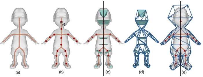
The pipeline of our method is summarized in Figure 2: start- 44
ing at the initial mesh with an underlying skeleton (a), the 45
user selects bending nodes (b); cutting surfaces across bend- 46
ing nodes are computed, and cross polygons are extracted from 47
them, which conform to the desired cross section of the cage, as 48
well as to the symmetry of the object (c); an initial tight cage is 49
obtained by connecting vertices of the cross polygons (d); the 50
cage is finally inflated and adjusted to avoid intersections (e). 51
Our main contributions are in steps (c) and (d) of the pipeline, 52
which both rely on the harmonic field mentioned above; we also 53
contribute for a pre-inflation in step (e), which is necessary to 54
enable the Nested cages by Sacht et al. [2] to perform final infla- 55
tion. Besides, we provide a complete working tool that requires 56
a level of interaction as simple as the one in step (b).Thanks to 57
the flexibility of our non-planar cuts, user interaction is greatly 58
simplified if compared to previous approaches [3], and impre- 59
cise inputs from the user are robustly handled, without affecting 60
the quality of the final cage (Figure 3). In Section 4, we also 61
show that a fully automatic initial placement of bending nodes 62
is possible, thus providing a fully automatic initial cage, which 63
can be edited and completed by the user at will. 64
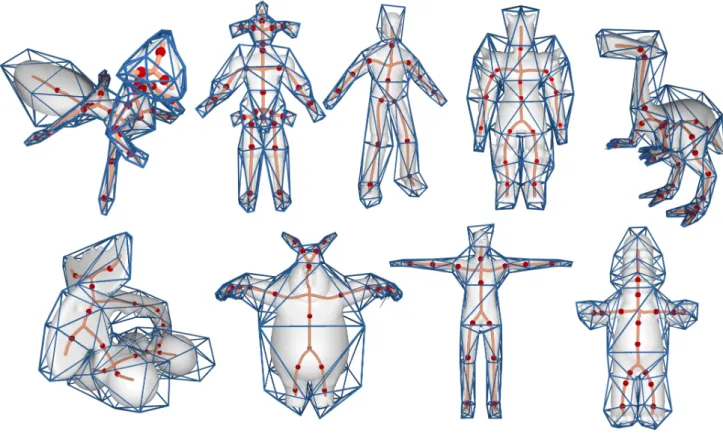
Our method enables the generation of high-quality coarse 65
cages with controlled topology, also for characters which are 66
not given in the standard T-pose (Figure 17). Our bounding 67
cages preserve all model features captured by the underlying 68
skeleton, as well as all user selected cross sections; at the same 69
time, they are robust against details that are not represented by 70
the skeleton and nicely envelope them too (Figure 13 and 12); 71
thus providing a desired/effective shape abstraction for anima- 72
tion purposes. 73
2. Related works 74
Early methods for cage generation based on the subdivision 75
of bounding boxes date back to late 80’s [11]. Despite the ro- 76
bustness, approaches of this kind lack the proper flexibility, and 77
are not suitable to generate cages that fulfill the requirements 78
animation imposes. In a recent survey, Nieto and Sus´ın [12] list 79
such requirements, also offering an overview of modern tech- 80
niques for automatic cage generation. The survey is still an 81
excellent resource for practitioners, but a few important tech- 82
niques have been released after its publication, both automatic 83
and user-assisted. 84
Several automatic methods define cages as a simplified ver- 85
sion of the character they contain [2, 13, 14, 15, 16, 17, 18], 86
and obtain them either by applying a decimation strategy (e.g. 87
[19]) or a remeshing technique at a coarser scale (e.g. [20]), of- 88
ten followed by vertex relocation to resolve intersections. Be- 89
ing purely geometric, these methods fail to be animation-aware, 90
meaning that cage handles may be distant from the parts the an- 91
imator wants to deform or bend. Furthermore, these methods 92
may disrupt the symmetry of the cage. For all these reasons, 93
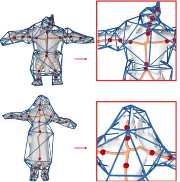
Fig. 2. Our pipeline starts from a digital character and its curve skeleton (a). The user manually selects nodes where bending occurs (b, red dots). Symmetric cross sections at bending nodes are obtained from a harmonic field in the volume (c). An initial cage is created by connecting the cross sections (d). The cage is finally inflated to accommodate the character without intersections (e).
or, at least, it requires substantial post-processing. Recently,
1
Calderon and Boubekeur [21] presented a shape approximation
2
algorithm which takes as input an arbitrary mesh and generates
3
a bounding proxy that tightly encloses it. Their method is
de-4
signed to support collision detection, thus it does not account
5
for semantically important structures. If automatically
com-6
puted, bounding proxies tend to be either too refined to be used
7
as coarse control cages, or they may affect the global topology
8
of the object, closing handles and filling holes. In order to
over-9
come such limitations, the local scale can be corrected with an
10
interactive brush. Our method automatically determines the
lo-11
cal scale of the cage that is necessary to accommodate all the
12
semantically relevant features of the character.
13
Similarly to us, template-based techniques [22, 23] use a
14
guiding skeleton to infer the logical components of the
char-15
acter, and cage it by using predefined templates chosen
accord-16
ing to type of joints of the underlying skeleton. Although these
17
methods can automatically construct cages for animation, they
18
are usually limited in the number of joints they can handle, and
19
do not scale on complex shapes with arbitrary topology. In
con-20
trast, our approach is able to handle any line skeleton, regardless
21
of its topology or the valence of its junction nodes. Chen and
22
Feng [24] substituted templates with planar cross-sections
lo-23
cally orthogonal to the skeleton. Depending on the complexity
24
of both the character and the pose, their approach may lead to
25
self-intersections.
26
The work of Le and Deng [3] is, to date, the most advanced
27
tool for interactive cage generation. The user constructs a
28
cage by sketching planar cross-sections on a 3D canvas. As
29
for [24], achieving a proper shape segmentation with planar
30
cross-sections may require substantial manual effort, and
de-31
signing a good cage around deep concavities remains
challeng-32
ing. The authors of [3] already acknowledge these limitations
33
in their article, and suggest the introduction of non-planar cross
34
sections to ameliorate their tool. Despite geometric limits,
cut-35
ting planes are also difficult to handle in the user interface.
Cre-36
ating a plane by sketching a segment on a 2D GUI requires a
37
deep 3D insight, and is extremely sensitive to the precision of 38
the user. Our non-planar cuts nicely complement the user inter- 39
face, making it easy to use and more robust against imprecise 40
inputs from the user (Figure 3). 41
Various works addressed the problem of producing a se- 42
quence of cage motions to compactly encode an animation 43
sequence [25, 24, 26, 27] or video-based animation [28]. This 44
latter problem is orthogonal to the one we address in this work, 45
with almost no algorithmic overlap. 46 47
Skeletons and semantics. Besides its application in cage gen- 48
eration and animation, curve-skeletons have been extensively 49
used as a mean to encode the structure of a 3D shape, and 50
have been exploited in a number of applications, ranging from 51
shape recognition [29, 30], consistent mesh partitioning [4, 31], 52
and re-meshing [32, 33, 34]. Our tool is inspired from these 53
latter works; however, the generation of animation cages 54
poses different constraints and goals, making none of these 55
approaches directly applicable to our needs. 56 57
Barycentric coordinates.Typically, the cage deformers are aug- 58
mented with coordinates, which impact the quality of the final 59
deformation. A plethora of different types of barycentric coor- 60
dinates have been proposed, including Mean Value Coordinates 61
[35, 36], Green Coordinates [37, 38], Harmonic Coordinates 62
[39, 40], Biharmonic Coordinates [1], and complex barycentric 63
coordinates and their variants [41, 42, 43]. The main differences 64
between the different types of coordinates regard their locality 65
and smoothness. The cages generated with our method support 66
any type of barycentric coordinates, which can be conveniently 67
chosen according to the animator’s needs. An interesting dis- 68
cussion of cage-based deformation techniques can be found in 69
3. Method
1
The pipeline of our method is described in Figure 2 and has
2
been summarized in the Introduction. In this section, we will
3
go through the details of each step.
4
Our input consists of a triangle mesh M representing the
dig-5
ital character, together with its line skeleton S. We just require
6
the skeleton to be fully contained in the volume bounded by the
7
mesh. Nodes of S that have more than two incident branches,
8
or just one incident branch, will be called branching nodes, and
9
leaf nodes, respectively. Additional nodes selected by the user
10
along the branches of the curve skeleton will be called bending
11
nodes.
12
Roughly speaking, the cage will be made of tubular
struc-13
tures, one for each branch of the skeleton, connected at
poly-14
hedral joints surrounding the branching nodes of S. Each
tubu-15
lar structure will have a polygonal cross section, and it will be
16
subdivided transversely at bending nodes. For simplicity, we
17
always adopt quadrilateral sections, as in [3], but the method
18
can support generic polygonal sections, possibly different for
19
each branch. Note that, although the boundaries of sections
20
may usually be nearly planar, their corresponding cutting
sur-21
faces are always forced to pass through the central node of the
22
skeleton and may result strongly non-planar(see e.g. the head
23
section in Figure 2). This feature is widely exploited by our
24
user interface, making it robust against imprecise inputs from
25
the user (Figure 3). Non-planarity will usually be emphasized
26
about leaf nodes and where relatively thin limbs are attached to
27
a larger body (e.g., armpit, groin).
28
3.1. Pre-processing: guiding field
29
Given the surface mesh M and the skeleton S, we define a
30
volumetric field that emanates radially from the skeleton to the
31
outer surface. Such a field is inspired by the radius component
32
of the cylindrical parameterization described in [32], and will
33
be used later on to partition our cage.
34
In order to compute this field, we first generate a tetrahedral
35
mesh that conforms to the outer surface of the character and
36
embeds the skeleton as chains of internal edges. We then
com-37
pute a harmonic function f defined over the volume spanned by
38
the tetrahedral mesh, by resolving the Laplace problem∆ f = 0,
39
subject to Dirichlet boundary conditions
40
f(p)= 0 ∀p ∈ S f(p)= 1 ∀p ∈ M.
The integral lines of f give us a robust way to project points
41
from the inner volume to the surface. Given any regular (i.e.,
42
non branching) point p on the skeleton, the integral lines of f
43
starting at p span a surface that cuts the volume transversely
44
with respect to S (Figure 4). We call this surface the cutting
45
surface at p. The cutting surface may bend according to the
46
local shape of M in the proximity of p, and it will intersect M
47
at a ring made of points that are “closer” to p than to any other
48
point of S.
49
Our guiding field has a consistent behaviour on meshes of
50
various density (Section 5), and therefore the tracing system
51
does not depend on a specific tetrahedralization. In our
imple-52
mentation we only take care of a few corner cases that may
53
flatten the field inside the volume and block the tracing of the 54
integral lines. Specifically, we split each inner edge having its 55
two endpoints exposed on the surface (or on the skeleton), and 56
also split each inner triangular face having all its vertices on the 57
surface (or on the skeleton). This guarantees that extending the 58
function by linear interpolation within each element, f will be 59
flat only at S and M.Note that the pre-processing is computed 60
off-line once, before any interaction occurs, and is used without 61
modification in later stages of our method. 62
3.2. User interaction 63
Similarly to [34, 33, 32] the input skeleton provides infor- 64
mation on the high level structure. Namely, how many limbs, 65
and how they connect to each other. The user may refine this 66
structure by prescribing additional degrees of freedom wherever 67
necessary. Interaction is intuitive and happens in real-time. 68
The user is just asked to click on skeleton curves where bend- 69
ing may occur (e.g., adding knees, elbows, wrists). This selec- 70
tion induces a partition of the skeleton that will then be trans- 71
lated into the cage. 72
User selected bending nodes will originate cutting surfaces, 73
which constitute a better alternative to the cutting planes used 74
in [3]. In fact, while cutting planes require accurate and te- 75
dious placement in 3D, our non-planar cutting surfaces are de- 76
termined solely from the bending nodes and make our method 77
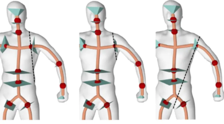
quite tolerant against inaccurate user selection (Figure 3). 78
Fig. 3. Example of cuts induced by different selections of bending nodes. The cyan pyramids approximate the cuts induced by the harmonic field, while the dashed black lines represent the corresponding cuts induced by a plane orthogonal to the skeleton and through the selected node. While our cuts are all valid, the corresponding planes may induce inconsistent cuts.
Notice that, if an animation skeleton is provided as input, 79
the cage partition will not necessarily reflect the same structure. 80
The user may freely decide whether the cage should be compli- 81
ant with it or not. 82
3.3. Cage generation 83
This is the core of our method. We start from the skeleton 84
S and the bending nodes added by the user, and we generate 85
a coarse cage that fits the input mesh M. Intersections be- 86
tween cage and mesh will be removed in a subsequent step of 87
the pipeline (Section 3.5). 88
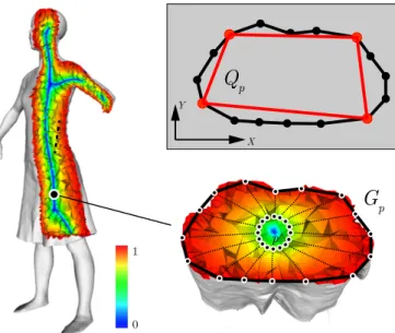
Let B be the set of bending nodes selected by the user, and 89
Q
p X YG
p p 0 1Fig. 4. We exploit the harmonic field f (left) to define the non planar cross sections of our cages. For each control point p we sample a ring locally orthogonal to the skeleton, and project it on the surface along the integral lines of f (bottom right). We project the resulting polygon Gpon the plane
defined by its PCA, and find the quadrilateral Qpthat better approximates
it (top right).
branches). We jointly refer to B ∪ L as control nodes. For each
1
control node p, we create a cross polygon which is roughly
or-2
thogonal to S and has its vertices on M. The cross polygon is
3
(a simplified version of) the boundary of a cutting surface and
4
will give a transversal section of the cage.
5
We first generate a sampling of the cutting surface at p by
6
tracing a number of integral curves of the harmonic field f .
7
Notice that f is encoded at the vertices of M and linearly
inter-8
polated inside each tetrahedron, thus its gradient field is
piece-9
wise constant. This fact may result in poor integral lines that
10
do not radially propagate in a uniform way, especially if they
11
are traced from the immediate proximity of S [45]. To avoid
12
this issue, we sample seeds on a circle centered at p and locally
13
orthogonal to S, and we trace the integral lines starting at such
14
seeds (see Figure 4, bottom right). The radius of the circle is a
15
fraction of the radius of the maximal ball centered at p and
en-16
closed in M (we use 20% in all our experiments); the number
17
of sampled points is a non-critical parameter of the method (we
18
sampled 20 points in all our experiments).
19
The integral lines we trace meet the surface M at a finite set
20
of points Gp, which provide a discrete approximation of the
in-21
tersection between the cutting surface at p and M itself. Note
22
that, as long as the skeleton is a deformation retract of M and
23
pis away from a branching node, such intersection should be a
24
ring; however, our method is tolerant to more complicated
sit-25
uations, like having saddles in the harmonic field or even
inter-26
secting the surface at multiple rings, as long as the main shape
27
is captured from a polygon spanning the points of Gp. Rings
28
here are just meant to initialize the cross sections, which will
29
be inflated as described in Section 3.5 to fully incorporate the
30
object.
31
We further approximate this ring with a polygon having its vertices at some of the points of Gp. We describe here a
tech-nique to generate a quadrilateral section Qp(q0, q1, q2, q3); it is
straightforward to extend it to a generic n-gon for any given n. Refer to Figure 4 for a graphical explanation of this procedure. We first compute the PCA of Gpand we take the first two
prin-cipal directions to define a XY planar frame. We then project Gpto such plane and select the four projected points that define
the quad Qpthat better aligns with the planar projection of Gp.
Let λ1, λ2be the two positive eigenvalues associated with the X
and Y axes given by the PCA: we define q0, q1, q2, q3as the four
points that maximize the signed sums of per vertex coordinates, weighted by λ1, λ2:
maxp∈Gp +λ1px+ λ2py
maxp∈Gp −λ1px+ λ2py
maxp∈Gp −λ1px−λ2py
maxp∈Gp +λ1px−λ2py.
In our figures, the cutting surface at p is approximated with 32
the pyramid obtained by connecting p to the vertices of Qp(Fig- 33
ures 2 and 3). 34
We complete the tubular portions of the cage by connecting 35
quad sections pairwise and computing their convex hull. No- 36
tice that the triangles generated between adjacent pairs of quad 37
sections are independent from the others, thus avoiding the ac- 38
cumulation of torsion along the limbs of the character. 39
We finalize the topology of the cage by welding together the 40
tubular structures we have built so far about the branching nodes 41
of S. We follow a technique similar to [3], considering one 42
branching node at a time and projecting its incident quad sec- 43
tions to a sphere centered at the center of mass of their vertices. 44
The convex hull of the so projected point set defines the con- 45
nectivity of the cage around each branching node (Figure 5). 46
Fig. 5. The tubular structures, corresponding to portions between consec-utive bending nodes along a branch of skeleton (blue) are joined with poly-hedra (green) centered about branching nodes of the skeleton to form the tight cage (before inflation).
Even if not reported in [3], we observe that in some patholog- 47
ical cases the convex hull algorithm may fail to define an edge 48
for each of the sides of the quadrilateral cross-sections, result- 49
ing in an invalid cage connectivity. If this is the case, we add a 50
Steiner vertex at the midpoint of each missed edge, and iterate 51
this operation until all the edges of the involved quad sections 52
are included in the convex hull. Additional vertices can be eas- 53
ily removed in post-processing by iteratively applying the edge 54
Fig. 6. Symmetrizing a quad across the symmetry planeΠ. Top: two ver-tices of the quad lie to the left ofΠ, and the other two lie to the right of Π – we impose symmetry of edges connecting vertices on the same side ofΠ. Bottom: two vertices lie onΠ and the other two lie on opposite sides of Π – we impose symmetry between the vertices not lying onΠ.
the edges that contain at least one Steiner vertex. The need for
1
insertion of Steiner points is very rare and we did not need it in
2
any of the cages we show.
3
3.4. Symmetry
4
In the digital modeling pipeline, most of the times only half
5
of a character is explicitly modelled, while the second half is
6
obtained by reflecting the so generated mesh along a symmetry
7
plane. In order to generate consistent animations for both sides
8
of a symmetric character, it is therefore important to replicate
9
such symmetries at cage level. We automatically detect
extrin-10
sic symmetry planes with the method described in [10], and use
11
them to adjust the position of cage sections and handles.
12
Let us consider a symmetry plane Π. Our strategy to
sym-13
metrize a cage works as follows. We consider each quad
sec-14
tion Qiand reflect it throughΠ, generating a target section QΠi.
15
We then find the quad section Qjthat is closest to QΠi . Distance
16
between quad sections is computed point-wise; since the
ver-17
tices of each quad section are ordered, we test the four possible
18
vertex pairings and consider the one that minimizes the sum of
19
pair-wise distances. If the two sections are not equivalent (i.e.
20
if i , j) we impose a symmetry between them, by computing
21
the average between Qj and QΠi, and using it and its reflected
22
counterpart to substitute Qjand Qi, respectively. If i = j, the
23
quad section is traversed by the symmetry plane. There are two
24
possible cases, summarized in Figure 6: (i) Qihas two out of
25
four vertices on Π, in which case we symmetrize the pair of
26
vertices which are not onΠ; (ii) none of the vertices of Qiis
27
onΠ, in which case we symmetrize the two edges of the quad
28
section, which do not crossΠ. Figure 7 shows a visual example
29
of cages obtained with and without symmetry enforcement.
30
This approach can be easily extended to deal with symmetric
31
characters given in general pose (which does not exhibit
ex-32
trinsic symmetry), by using the method for intrinsic symmetry
33
detection described in [10].
34
3.5. Cage inflation
35
The tight cage we have built so far has its vertices on the skin
36
M. In the final step of our method, we pull the vertices of the
37
cage further out, ensuring that none of its faces intersects M.
38
Fig. 7. A visual comparison between a cage without (left) and with (right) symmetry enforcement on the Boy dataset.
We inflate the cage using the Nested Cages expansion mecha- 39
nism [2]. This is all but straightforward, though. Such a method 40
is efficient and guarantees the absence of collisions. However, 41
as already acknowledged by the authors, it may fail if the tight 42
cage and the skin are not sufficiently close to each other (see 43
Figure 8). We address this issue by pre-inflating the tight cage 44
before the final inflation with Nested cages. 45
Fig. 8. Nested Cages [2] may fail without our pre-inflation mechanism. Even though all vertices of the tight cage are on the surface, on the ab-domen of the ant its faces are too far from the skin to support skin contrac-tion, which is at the basis of the Nested Cages algorithm. Antcat dataset.
We pull cage faces towards the outer surface of M with a 46
simple technique summarized in Figure 9. We sample the faces 47
of the cage and we project each sample onto M by following the 48
integral lines of the harmonic field f (Section 3.1). Samples that 49
are already outside the skin are ignored. For each face fiof the 50
cage, we take the sample s that lies farthest from its projection 51
sp, and define a face displacement vector ~fi = sp − s. Then, 52
for each vertex vjof the cage, we build a vertex displacement 53
vector ~vjas follows: 54
• the direction of ~vj is the (normalized) average of the per 55
face displacements vectors incident at vj(Figure 9, left); 56
• the magnitude of ~vjis the length of the largest projection of 57
the same face displacement vectors on this direction (Fig- 58
ure 9, right). 59
Since every vertex of the cage is moving out from the surface 60
of the model, the cage could self-intersect during pre-inflation. 61
This may happen in the proximity of tiny features or small spac- 62
ing between different parts of the model. This is easily fixed as 63
Fig. 9. Pre-inflation of the cage. Left: each face is assigned a displacement vector that brings it closer to the skin. Right: such displacements are aver-aged at cage vertices to pull them outwards.
after pulling them outwards; then, for each pair of intersecting
1
faces, we move all their vertices a small step towards their
pre-2
vious positions, and we repeat until no intersection occurs: the
3
offset at each step is set as a small fraction of the displacement
4
vector ~vjdefined above.
5
In all our experiments, this procedure was sufficient to
pro-6
vide a clean input to Nested cages. In case final inflation still
7
fails, in most of the cases the number of bending nodes selected
8
by the user was not sufficient to provide a fine enough
articu-9
lation of the cage. This is easily fixed with one more cycle of
10
interaction.
11
Note that although a symmetric energy is presented in [2],
12
the available implementation of Nested Cages does not
sup-13
port symmetry. We therefore interleave cage inflation and
sym-14
metrization (Section 3.4) of the cage to obtain the desired result.
15
4. Automatic placement of bending nodes
16
Although the method we are proposing is designed to be
user-17
assisted, we may also suggest an initial guess of bending nodes.
18
The rationale consists in placing bending nodes in
correspon-19
dence of abrupt changes in the local thickness of the shape (e.g
20
where arms and torso meet). This is a classical criterion for
21
mesh segmentation [46], and it is sometimes sufficient to
ob-22
tain a fully automatic construction of the cage. In most cases,
23
though, it just provides some hint to the user, as bending points
24
may not match geometrically relevant features of the mesh.
25
We propose here a simple heuristic which exploits the
curve-26
skeleton. Alternative strategies to segment a shape based on its
27
local thickness exist in literature and may accommodate better
28
results. We define a function over the curve skeleton S
29
r(p)= Rad(p) ∀p ∈ S,
where Rad(p) is the radius of the maximal sphere centered at
30
p, which is fully inscribed inside the model. Function r is
pro-31
vided as a byproduct of skeleton computation by several
meth-32
ods [6, 7]. In case it is not available from the input, it can be
33
easily computed by finding the point on the character that is
34
closest to p. We place bending nodes at points of the skeleton
35
where there is a large variation of function r. We compute the
36
first derivative r0and we find its critical points. To alleviate
sen-37
sitivity to the noise, we smooth function r0before using it. From
38
Fig. 10. A collection of cages obtained by running our pipeline in fully auto-matic mode. Boy, Scape, Horse, Homer and Animal datasets. Some bend-ing points may be either missbend-ing (e.g., ankles and knees for Homer), or redundant (ankles for Scape, elbows for Animal, head for Homer).
a practical point of view, this method allows us to further speed 39
up the cage construction. Starting at the initial guess, inter- 40
action is limited to adding/removing/displacing bending nodes. 41
Despite its simplicity, this strategy already allowed us to pro- 42
duce some quality cages without any user interaction. See Fig- 43
ure 10. 44
Fig. 11. Cage of the Dance dataset. Even if the skirt is not properly cap-tured by the skeleton, our algorithm is able to produce a quality cage that tightly encloses it (see closeup).
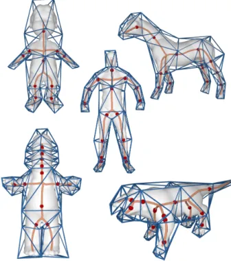
5. Results and discussion 45
We implemented our cage generation tool as a single 46
threaded C++ application and run our experiments on a Mac- 47
Fig. 12. Models Warrok (top) and Ganfaul (bottom) contain spiky elements or protrusions that are not captured by the skeleton. The close-up (right) of the spiky elements in these models is shown. Our method is tolerant to these features and builds a cage that correctly contains them.
Fig. 13. The Asian dragon model with two different skeletons: on the left, a coarser cage is generated embedding all the spikes which are not repre-sented by the skeleton; on the right, a high-resolution cage captures the finer protrusions (fingers, tail, horns) of the input model.
RAM. In the context of the pipeline, we have used a few well
es-1
tablished techniques implemented in a variety of publicly
avail-2
able libraries, specifically: Tetgen [47] for volumetric mesh
3
generation; CGAL [48] to compute convex hulls; Eigen [49] to
4
solve linear systems; and anonymized [50] for mesh and scalar
5
field processing. A reference implementation of our tool can be
6
found on GitHub at the following address: anonymized.
7
We have applied our caging tool to a variety of 3D models
8
listed in Table 1, producing cages that fulfill all the
require-9
ments listed in [3, 12] and reflect the extrinsic symmetries of
10
models. Skeletons were computed using the implementation
11
of [8] available in CGAL, as well as other automatic [6, 7]
12
and interactive [9] techniques. Galleries of cages obtained with
13
our method are shown in Figures 16 and 17, for models with
14
and without extrinsic bilateral symmetry, respectively. Notice
15
that we effectively deal with rather complex objects and poses,
16
like the Joker, the Octopus and the two dragons. In addition to
17
that, we observed that despite its natural ability to cage tubular
18
shapes, also digital characters with features that are not well
de-19
scribed by a skeleton, such as the skirt in Figure 11, are robustly
20
Fig. 14. Comparison between cages obtained with: aggressive mesh deci-mation followed by inflation via Nested Cages [2] (left column); interactive cutting planes [3] (middle column); our method (right column). Scape, Tyra and Fertility datasets.
handled. 21
Despite the ability of the user to control the caging process 22
by prescribing bending nodes, an additional source of control 23
is granted by the skeleton itself, which sets the overall struc- 24
ture of the cage. Coarse skeletons that do not catch all the tiny 25
protuberances of a shape induce a simplified cage (Figure 12), 26
while finer skeletons are able to catch all the tiny details of the 27
character and enable an explicit control of such structures for 28
animation (Figure 13). 29
We also validated our cages by posing digital characters us- 30
ing the CageLab tool [51]; some of the key poses we generated 31
are depicted in Figure 19. See also the accompanying video. 32
Comparisons. In Figure 14 we compare our results with two 33
state-of-the-art methods for caging, one automatic and one in- 34
teractive. For automatic caging, we combined aggressive mesh 35
decimation [19] with inflation with Nested Cages [2]. For in- 36
teractive caging, we considered the recent method of Le and 37
Deng [3]. Since we started from the cage meshes provided 38
by [3], we generated our results and the results of the auto- 39
matic approach so as to produce cages with similar complexity 40
(i.e. same amount of vertices). To the best of our knowledge, 41
there exists no benchmark to compare two alternative cages of 42
the same character, or to evaluate a given character for specific 43
animation tasks. Here we therefore compare the cages based on 44
the principles devised by previous literature, and listed in Sec- 45
Fig. 15.Top: The caging method of [3] fails to generate a valid cage (see the self-intersection in the close-up). As discussed in their paper (Section 4), this problem stems from the use of unbounded planar cuts. Bottom: Our method produces a valid cage that contains the character and is free from self-intersections.
fully automatic caging fails to preserve symmetry, it misses
im-1
portant bending points, and it produces a highly irregular cage.
2
On the other hand, both interactive methods produced similar
3
cages, with no perceivable defects.
4
Interaction-wise, we observe that our cutting system is able to
5
robustly and reliably split the cage around a bending area, even
6
if the user is not very precise in selecting the bending node
(Fig-7
ure 3). Conversely, the method of Le and Deng [3] is based
8
on sketching a cutting plane by drawing a segment on a 2D
9
GUI. Such an operation that is much more complex, requires a
10
deeper 3D insight, and is extremely sensitive to the precision of
11
the user. This type of interaction operation takes minutes, let
12
alone further adjustments that may be necessary to solve
intri-13
cate configurations. We argue that our interaction is faster: We
14
only require the user to click on the skeleton to locate bending
15
points, which can be done in a few seconds (Table 1, Tui).
Fi-16
nally, as acknowledged in [3], the use of unbounded planar cuts
17
may produce invalid cages containing self-intersections that are
18
not easy to remove. We also observe that their heuristic for cage
19
inflation is purely based on a distance function with respect to
20
the character skin, and does not guarantee (and does not even
21
promote) the absence of self-intersections in the cage.
There-22
fore, these pathological configurations cannot be recovered. In
23
Figure 15, we show a self-intersecting cage produced with [3],
24
together with our (valid) result.
25
Figure 20 shows a comparison with respect to the
bound-26
ing shapes produced by the recent automatic method presented
27
in [21]. Although such method is not meant to produce cages
28
for animation, we notice that they nicely enclose the
charac-29
ters in rather tight cages. However, as for the other automatic
30
method we compare with, the distribution of vertices in such
31
cages totally misses the semantics needed for animation. In
32
[21], coarser cages are also shown, which were not released to
33
the public domain for comparison. So we argue that they may 34
possibly produce cages as coarse as ours, but without consider- 35
ing a proper placement of control points. Moreover, aggressive 36
simplification of the envelope may change the global topology 37
of the cage, e.g., by joining two feet/legs if they rest close to 38
each other, as shown in several examples in [21]. This is indeed 39
a benefit for application in collision detection, while it makes 40
the cage no longer suitable for animation. Finally, in order to 41
obtain variable resolution, e.g., to build a cage that may con- 42
trol every single finger of a hand, they need interaction with a 43
virtual brush, which is probably heavier than the placement of 44
bending nodes in our method. 45
Resolution. Our method exposes a good independence from 46
mesh resolution, both at a surface and volumetric level. 47
Surface-wise, a good caging algorithm should focus on the high 48
level appearance of a digital character, and not on low-level tes- 49
sellation details. Ideally, the influence of the latter should be 50
negligible. We demonstrate this property in Figure 21, where 51
we consider two very different triangulations of the Tyra, ob- 52
taining two cages which are similar to one another. Volume- 53
wise, we studied how much the volumetric discretization of the 54
character influences the final result. As it can be noticed in 55
Figure 22, the behaviour of the level sets and integral lines of 56
the field remains consistent at different resolutions, making the 57
algorithm substantially independent from the volumetric dis- 58
cretization. This is very important, because it means that the 59
generation of the tetrahedral mesh is not a hidden parameter 60
difficult to deal with, and that the algorithm can be reproduced 61
by other developers. 62
Timing. Processing times for the various models used in our 63
experiments are reported in Table 1. Pre-processing is per- 64
formed once as the model is loaded and times depend on the 65
complexity of the input models, varying between less than one 66
second to about one minute in our experiments. Roughly speak- 67
ing, user interaction requires about one second per bending 68
node selected on the skeleton, making this phase about one or- 69
der of magnitude faster than user-assisted techniques based on 70
cutting planes. The construction of the base complex and its 71
pre-inflation phases together report times from less than one 72
second to about three seconds for all models, except the Tyra 73
at high resolution, which requires almost 20 seconds. Over- 74
all, these phases are compatible with an interactive usage: the 75
topology of the cage is immediately visible on the base com- 76
plex, and the user is allowed to cycle on them to edit the bend- 77
ing nodes and correct the cage after running the final inflation. 78
The final inflation with Nested Cages is computation inten- 79
sive and requires between 45 seconds for the simplest model to 80
about 15 minutes for the hi-res Tyra. Although this last phase is 81
typically one-shot, long processing times may be not compati- 82
ble with practical usage. In order to bring processing times to 83
reasonable bound, even with high resolution characters – such 84
as the ones created with 3D sculpting tools like ZBrush [52] – 85
a relevant speedup can be achieved by substituting the original 86
character with a proxy shape obtained via aggressive mesh dec- 87
imation [19]. A cage built upon a low-res proxy containing just 88
Fig. 16. A collection of cages for models with extrinsic symmetry: Antcat, Jocker, Skater, Warrior, Dinopet, Elk, BigBunny, ManTpose and Homer.
Fig. 18.Left: Our method fails to produce a valid cage if the number of se-lected bending nodes is not sufficient to accommodate the geometry of the character. Inflating such an unrefined cage to contain the whole octopus is in fact impossible, as cage self-intersections will arise. Right: The user can easily recover from such pathological cases by prescribing additional bend-ing nodes, which in turn produce a more refined cage that tightly encloses the whole octopus.
Fig. 19. Different poses of the Horse dataset obtained by editing a cage produced with our technique. For cage editing we used CageLab [51].
giving a result quite close to the final one. The full resolution
1
character is eventually re-introduced for a further step of
infla-2
tion with Nested Cages, which takes in input the cage inflated
3
about the proxy. Thanks to this warm start in the final inflation,
4
the total time required with this techniques is much less than
5
that the time spent by the method running directly on the hi-res
6
model.
7
In Table 1 we report two examples of this approach. To give
8
concrete numbers, building a cage directly for the high
reso-9
lution version of the Gecko (∼75K tris) required 870 seconds,
10
while the whole pipeline required just 40 seconds on the low
11
resolution proxy (1000 tris); with an additional 130 seconds for
12
the final inflation, the cage was adapted to the hi-res model,
13
yielding a 80% speedup. With the more complex Tyra (200K
14
tris),and a relatively larger proxy (25K tris), we still get a 50%
15
speedup.
16
6. Limitations
17
Even though our method can produce quality cages for a
va-18
riety of characters of any topology, we are limited to the class
19
of shapes that admit a skeletal representation. Although in the
20
world of digital characters this is by far the dominant class of
21
shapes, more complex shapes, such as those containing large
22
Fig. 20.Visual comparison between the state of the art caging method for collision detection [21] (left), and our method (right). General purpose cages are not suitable for animation, as they introduce unnecessary ver-tices, and do not align with the semantic features of the character.
and thin surfaces, may also occur. Such shapes may be ad- 23
dressed with the use of mixed line-sheet skeletons [53, 8]. Our 24
approach can be extended to deal with such skeletons by just 25
allowing the user to select bending lines on sheets, beside bend- 26
ing points on the line skeleton; the method for extracting cross 27
sections based on the harmonic field nicely extends to this case, 28
too. We plan to tackle these issues in our future work. 29
A second limitation is that, in some pathological cases, our 30
method may fail to produce a valid cage if the user selects an 31
insufficient number of bending points (Figure 18). This relates 32
with the fact that keeping the topology of the cage fixed, i.e., 33
totally determined by the skeleton and its bending points, the 34
only mechanism to resolve intersections is inflation. For mod- 35
els having insufficient bending points and narrow tubular fea- 36
tures with high curvature this may therefore result in excessive 37
inflation, possibly resulting in collisions with distant parts of 38
the character, and intersections that cannot be removed with- 39
out refining the topology of the cage further. In all these cases, 40
Nested Cages [2] fails. The user can easily address this issue 41
by just adding one or more bending points in the pathological 42
areas and running the automatic part of the method again. A 43
Fig. 21.Our method is substantially independent from the resolution of the input mesh. Here we show two cages, obtained by processing two alterna-tive discretizations of the same character. Despite that the input meshes are very different in size (24K triangles vs 200K triangles), the output cages are quite similar.
monic field, which requires a volumetric discretization of the
1
interior of the character. While this may seem to suggest that
2
surface meshes containing topological defects or open
bound-3
aries cannot be processed with our method, we point out that
4
scientific literature offers a variety of methods for mesh
repair-5
ing (e.g., MeshFix [54]) and robust tetmesh extraction (e.g.,
6
TetWild [55]). Therefore, having a watertight 2-manifold is not
7
a strict requirement.
8
7. Conclusion and future work
9
We have presented a novel user-assisted method for building
10
animation cages. As demonstrated by a variety of results, our
11
algorithm scales well to complex shapes, which can be either
12
provided in the canonical T-pose, or in arbitrary pose.
13
Compared to similar approaches [3], we offer a faster, more
14
intuitive, and more robustuser interaction, requiring just the
15
selection of bending points on the skeleton. Placement of cage
16
nodes is based on a flexible and reliable criterion, which allows
17
for curved cross-sections extracted from a harmonic field in the
18
volume, thus overcoming the popular (but tedious and limiting)
19
cutting planes.
20
In a very recent paper [56], evidence is presented that mixed
21
tri-quad cages can provide better control to animation and
de-22
formation. The extension of our method to support such cages
23
is straightforward, as all cage elements along limbs and across
24
the symmetry plane are naturally defined as quads.
25
References
26
[1] Jacobson, A, Baran, I, Popovic, J, Sorkine, O. Bounded Biharmonic 27
Weights for Real-time Deformation. ACM Trans Graph 2011;30(4):78:1– 28
78:8. 29
[2] Sacht, L, Vouga, E, Jacobson, A. Nested cages. ACM Trans Graph 30
2015;34(6):170:1–170:14. 31
[3] Le, BH, Deng, Z. Interactive Cage Generation for Mesh Deformation. 32
In: Proceedings of the 21st ACM SIGGRAPH Symposium on Interactive 33
3D Graphics and Games. I3D ’17; New York, NY, USA: ACM; 2017, p. 34
3:1–3:9. 35
Fig. 22.The behaviour of the level sets (hence the integral lines) of the guiding harmonic field we use to propagate the cutting surfaces remains consistent at all resolutions. This makes our method substantially inde-pendent from the volumetric discretization we use to define the field. Here we show two alternative cages of the same character, obtained by process-ing the same input mesh, but usprocess-ing two different volumetric tessellations (117K tets vs 643K tets). The two cages are quite similar.
[4] Zhou, Y, Yin, K, Huang, H, Zhang, H, Gong, M, Cohen-Or, D. Gen- 36 eralized Cylinder Decomposition. ACM Trans Graph 2015;34(6):171:1– 37
171:14. 38
[5] Tagliasacchi, A, Delame, T, Spagnuolo, M, Amenta, N, Telea, A. 39 3D Skeletons: A State-of-the-Art Report. Computer Graphics Forum 40
2016;35(2):573–597. 41
[6] Livesu, M, Scateni, R. Extracting Curve-Skeletons from Digital Shapes 42 Using Occluding Contours. The Visual Computer 2013;29(9):907–916. 43 [7] Livesu, M, Guggeri, F, Scateni, R. Reconstructing the Curve-Skeletons 44 of 3D Shapes Using the Visual Hull. IEEE Transactions on Visualization 45 and Computer Graphics 2012;18(11):1891–1901. 46 [8] Tagliasacchi, A, Alhashim, I, Olson, M, Zhang, H. Mean curvature 47 skeletons. Computer Graphics Forum 2012;31(5):1735–1744. 48 [9] Barbieri, S, Meloni, P, Usai, F, Spano, LD, Scateni, R. An Inter- 49 active Editor for Curve-Skeletons: SkeletonLab. Computer & Graphics 50
2016;60:23–33. 51
[10] Panozzo, D, Lipman, Y, Puppo, E, Zorin, D. Fields on Symmetric 52 Surfaces. ACM Trans Graph 2012;31(4):111:1–111:12. 53 [11] Sederberg, TW, Parry, SR. Free-form Deformation of Solid Geometric 54 Models. SIGGRAPH Comput Graph 1986;20(4):151–160. 55 [12] Nieto, JR, Sus´ın, A. ”Cage Based Deformations: A Survey”. In: 56 Gonz´alez Hidalgo, M, Mir Torres, A, Varona G´omez, J, editors. De- 57 formation Models: Tracking, Animation and Applications. Dordrecht: 58 Springer Netherlands. ISBN 978-94-007-5446-1; 2013, p. 75–99. 59 [13] Xian, C, Li, G, Xiong, Y. Efficient and effective cage genera- 60 tion by region decomposition. Computer Animation and Virtual Worlds 61
2015;26(2):173–184. 62
[14] Xian, C, Lin, H, Gao, S. Automatic cage generation by improved OBBs 63 for mesh deformation. The Visual Computer 2012;28(1):21–33. 64 [15] Deng, ZJ, Luo, XN, Miao, XP. Automatic Cage Building with 65 Quadric Error Metrics. Journal of Computer Science and Technology 66
2011;26(3):538–547. 67
[16] Ben-Chen, M, Weber, O, Gotsman, C. Spatial Deformation sfer. In: 68 Proceedings of the 2009 ACM SIGGRAPH/Eurographics Symposium on 69 Computer Animation. SCA ’09; New York, NY, USA: ACM; 2009, p. 70
67–74. 71
[17] Xian, C, Lin, H, Gao, S. Automatic generation of coarse bounding 72 cages from dense meshes. In: Shape Modeling and Applications, 2009. 73
Model Figure Mv Mf BN Cv Cf Tpp Tui Tbc Tin f Tnc Ttot Tnc∗ Animal 10 19552 39040 16 84 164 6.74 15 1.02 0.29 813.26 836 Antcat 8;16 1550 3096 29 156 308 0.66 17.75 0.16 0.26 45.37 64 Armadillo 1 10002 20000 17 100 196 2.92 13.2 0.75 0.33 135.21 152 Asian Dragon 13 10000 19996 17 96 188 3.11 15.89 0.61 2.46 108.54 131 Asian Dragon 13 10000 19996 51 348 692 3.45 50.32 1.43 1.17 169.21 226 Beast 20 15122 30264 15 76 148 5.26 10 0.6 0.22 887.38 903 BigBunny 16 21763 43522 14 108 212 10.2 12.22 2.43 1.1 541.5 567 Boy 7;10;20 7502 15000 16 84 164 2.34 12.53 0.5 0.32 67.88 84 Cat 17 27246 54488 19 108 212 11.73 13.11 1.55 0.5 297.76 325 Dance 4;11 9971 19938 13 72 140 3.52 11.99 0.33 0.14 102.28 118 Dinopet 16 4500 8996 27 156 308 1 20.1 0.33 0.34 70.6 92 Dragon 17 5000 10000 22 124 284 1.47 14.58 0.35 0.2 109.7 126 Elk 16 23114 46228 15 88 176 7.14 11.2 1.29 0.14 170.12 190 Fertility 14 9994 20000 23 92 196 33.01 16.59 0.26 0.34 147 197 Ganfaul 12 14590 29192 15 76 148 4.12 12.54 0.58 0.29 491.32 509 Gecko (high) 17 37352 74700 24 120 236 12.55 14.54 1.96 0.68 840 870 Gecko (low) 17 500 1000 24 120 236 0.15 16.45 0.06 0.16 23.37 40 130 Hand 17 14347 28690 15 84 164 5.2 13.5 0.7 0.2 197.27 217 Homer 10 12997 25990 16 84 164 4.79 13.7 0.62 0.32 80.45 100 Horse 10;19 19850 39696 15 76 148 8.67 9.55 0.8 0.29 175.49 195 Joker 17 13328 26652 22 132 260 4.26 13.25 1.52 0.39 191.89 211 Lion 17 27899 55794 17 92 180 10.18 15.2 1.22 0.4 152.06 179 ManTpose 16 13356 26708 14 76 148 4.02 10.2 0.51 0.11 86.05 101 Octopus 17 10002 20000 47 224 444 3.09 30.13 0.76 0.51 62.61 97 Scape 5;10;14 6318 12632 15 80 156 1.19 12.6 0.2 0.11 62.94 77 Skater 16 13332 26660 14 76 148 4.59 10.26 0.68 0.18 112.23 128 Tyra (high) 14 100002 200000 33 184 364 54.99 22.1 17.51 1.65 886 982 Tyra (low) 14 12501 24998 33 184 364 4.56 22.45 1.41 0.67 386.48 416 90 Warrior 16 9474 18944 17 88 172 3.02 14.21 0.33 0.15 72.12 90 Warrok 12 23528 11746 19 96 188 3.11 18.25 0.43 0.26 666.74 689
Table 1. Size of meshes and timing for the whole pipeline (user-assisted cages only): Mvand Mf are the vertices and faces of the input model; BN are the
bending nodes selected in the interactive stage; Cvand Cf are the vertices and faces of the cage; Tppis the pre-processing time; Tuiis the user interaction
time; Tbcis the time required to build the base complex; Tinfis the time required to inflate the base complex; Tncis the time for the execution of the Nested
Cages algorithm; Ttotis the sum of the times in the previous columns rounded to integer. Tnc∗is the time for the final Nested Cages when the model is used
as a proxy for the hi-res model in the previous row. All times are in seconds.
SMI 2009. IEEE International Conference on. IEEE; 2009, p. 21–27. 1
[18] Sander, PV, Gu, X, Gortler, SJ, Hoppe, H, Snyder, J. Silhouette 2
Clipping. In: Proceedings of the 27th Annual Conference on Computer 3
Graphics and Interactive Techniques. SIGGRAPH ’00; New York, NY, 4
USA: ACM Press/Addison-Wesley Publishing Co.; 2000, p. 327–334. 5
[19] Garland, M, Heckbert, PS. Surface simplification using quadric er-6
ror metrics. In: Proceedings of the 24th annual conference on Com-7
puter graphics and interactive techniques. ACM Press/Addison-Wesley 8
Publishing Co.; 1997, p. 209–216. 9
[20] Kazhdan, M, Bolitho, M, Hoppe, H. Poisson Surface Reconstruction. 10
In: Sheffer, A, Polthier, K, editors. Symposium on Geometry Processing. 11
The Eurographics Association. ISBN 3-905673-24-X; 2006,. 12
[21] Calderon, S, Boubekeur, T. Bounding Proxies for Shape Approximation. 13
ACM Trans Graph 2017;36(5):57:1–57:13. 14
[22] Yang, X, Chang, J, Southern, R, Zhang, JJ. Automatic cage construction 15
for retargeted muscle fitting. The Visual Computer 2013;29(5):369–380. 16
[23] Ju, T, Zhou, QY, van de Panne, M, Cohen-Or, D, Neumann, U. 17
Reusable skinning templates using cage-based deformations. ACM Trans 18
Graph 2008;27(5):122:1–122:10. 19
[24] Chen, X, Feng, J. Adaptive skeleton-driven cages for mesh sequences. 20
Computer Animation and Virtual Worlds 2014;25(3-4):445–453. 21
[25] Chen, X, Feng, J, Bechmann, D. Mesh Sequence Morphing. Computer 22
Graphics Forum 2016;35(1):179–190. 23
[26] Thiery, JM, Tierny, J, Boubekeur, T. CageR: Cage-Based Re- 24 verse Engineering of Animated 3D Shapes. Computer Graphics Forum 25
2012;31(8):2303–2316. 26
[27] Chen, L, Huang, J, Sun, H, Bao, H. ”Cage-based deformation transfer”. 27 Computers & Graphics 2010;34(2):107 – 118. 28 [28] Savoye, Y. Cage-based Performance Capture. In: SIGGRAPH ASIA 29 2016 Courses. SA ’16; New York, NY, USA: ACM; 2016, p. 12:1–12:53. 30 [29] Kin-Chung Au, O, Tai, CL, Cohen-Or, D, Zheng, Y, Fu, H. Elec- 31 tors voting for fast automatic shape correspondence. Computer Graphics 32
Forum 2010;29(2):645–654. 33
[30] Biasotti, S, Marini, S, Spagnuolo, M, Falcidieno, B. Sub-part corre- 34 spondence by structural descriptors of 3D shapes. Computer-Aided De- 35
sign 2006;38(9):1002–1019. 36
[31] Mortara, M, Patan`e, G, Spagnuolo, M. From geometric to semantic 37 human body models. Computers & Graphics 2006;30(2):185–196. 38 [32] Livesu, M, Attene, M, Patan`e, G, Spagnuolo, M. Explicit Cylindrical 39 Maps for General Tubular Shapes. Computer-Aided Design 2017;90:27 40
– 36. SI:SPM2017. 41
[33] Livesu, M, Muntoni, A, Puppo, E, Scateni, R. Skeleton-driven Adap- 42 tive Hexahedral Meshing of Tubular Shapes. Computer Graphics Forum 43
2016;35(7):237–246. 44
[34] Usai, F, Livesu, M, Puppo, E, Tarini, M, Scateni, R. Extraction of 45 the Quad Layout of a Triangle Mesh Guided by Its Curve Skeleton. ACM 46
Trans Graph 2015;35(1):6:1–6:13. 1
[35] Floater, MS. Mean value coordinates. Computer aided geometric design 2
2003;20(1):19–27. 3
[36] Ju, T, Schaefer, S, Warren, J. Mean Value Coordinates for Closed 4
Triangular Meshes. ACM Trans Graph 2005;24(3):561–566. 5
[37] Lipman, Y, Levin, D, Cohen-Or, D. Green Coordinates. ACM Trans 6
Graph 2008;27(3):78:1–78:10. 7
[38] Lipman, Y, Kopf, J, Cohen-Or, D, Levin, D. GPU-assisted Positive 8
Mean Value Coordinates for Mesh Deformations. In: Geometry Process-9
ing. The Eurographics Association; 2007,. 10
[39] Joshi, P, Meyer, M, DeRose, T, Green, B, Sanocki, T. Harmonic coordi-11
nates for character articulation. ACM Trans Graph 2007;26(3):71:1–71:9. 12
[40] DeRose, T, Meyer, M. Harmonic coordinates. In: Pixar Technical Memo 13
06-02, Pixar Animation Studios. 2006,. 14
[41] Garc´ıa, FG, Paradinas, T, Coll, N, Patow, G. *Cages:: A Multilevel, 15
Multi-cage-based System for Mesh Deformation. ACM Trans Graph 16
2013;32(3):24:1–24:13. 17
[42] Ben-Chen, M, Weber, O, Gotsman, C. Variational Harmonic Maps for 18
Space Deformation. ACM Trans Graph 2009;28(3):34:1–34:11. 19
[43] Zhang, J, Deng, B, Liu, Z, Patan`e, G, Bouaziz, S, Hormann, K, et al. 20
Local Barycentric Coordinates. ACM Trans Graph 2014;33(6):188:1– 21
188:12. 22
[44] Jacobson, A, Deng, Z, Kavan, L, Lewis, J. Skinning: Real-time Shape 23
Deformation. In: ACM SIGGRAPH 2014 Courses. 2014,. 24
[45] Mancinelli, C, Livesu, M, Puppo, E. A Comparison of Methods for 25
Gradient Field Estimation on Simplicial Meshes. Computers & Graphics 26
2019;. 27
[46] Shamir, A. A survey on mesh segmentation techniques. In: Computer 28
graphics forum; vol. 27. Wiley Online Library; 2008, p. 1539–1556. 29
[47] Si, H. TetGen, a Delaunay-Based Quality Tetrahedral Mesh Generator. 30
ACM s Math Softw 2015;41(2):11:1–11:36. 31
[48] Fabri, A, Pion, S. CGAL: The Computational Geometry Algorithms 32
Library. In: Proceedings of the 17th ACM SIGSPATIAL International 33
Conference on Advances in Geographic Information Systems. GIS ’09; 34
New York, NY, USA: ACM; 2009, p. 538–539. 35
[49] Guennebaud, G, Jacob, B, et al. Eigen v3. http://eigen.tuxfamily.org; 36
2010. 37
[50] Anonymous, . Anonymized reference. ???? 38
[51] Casti, S, Corda, F, Livesu, M, Scateni, R. CageLab: an Interactive Tool 39
for CageBased Deformations. In: Smart Tools and Apps for Graphics -40
Eurographics Italian Chapter Conference. The Eurographics Association. 41
ISBN 978-3-03868-075-8; 2018,. 42
[52] Pixologic, . ZBrush. 2007. http://pixologic.com. 43
[53] Martin, T, Chen, G, Musuvathy, S, Cohen, E, Hansen, C. General-44
ized swept mid-structure for polygonal models. Comput Graph Forum 45
2012;31(2pt4):805–814. 46
[54] Attene, M. A lightweight approach to repairing digitized polygon 47
meshes. The visual computer 2010;26(11):1393–1406. 48
[55] Hu, Y, Zhou, Q, Gao, X, Jacobson, A, Zorin, D, Panozzo, D. 49
Tetrahedral meshing in the wild. ACM Transactions on Graphics (TOG) 50
2018;37(4):60. 51
[56] Thiery, JM, Memari, P, Boubekeur, T. Mean value coordinates for quad 52
cages in 3D. ACM Trans Graph - Proc SIGGRAPH Asia 2018 ????;To 53
appear. 54
![Fig. 1. Left: a purely geometric segmentation obtained with a state-of-the- state-of-the-art method [4] does not capture bending junctions between disjoint seman-tic parts (neck, elbows, knees, wrists, joints of fingers and toes)](https://thumb-eu.123doks.com/thumbv2/123doknet/14226405.484693/3.892.67.441.259.438/geometric-segmentation-obtained-capture-bending-junctions-disjoint-fingers.webp)
![Fig. 8. Nested Cages [2] may fail without our pre-inflation mechanism.](https://thumb-eu.123doks.com/thumbv2/123doknet/14226405.484693/7.892.524.786.526.661/fig-nested-cages-fail-pre-inflation-mechanism.webp)
![Fig. 15. Top: The caging method of [3] fails to generate a valid cage (see the self-intersection in the close-up)](https://thumb-eu.123doks.com/thumbv2/123doknet/14226405.484693/10.892.61.419.103.409/fig-caging-method-fails-generate-valid-intersection-close.webp)
![Fig. 20. Visual comparison between the state of the art caging method for collision detection [21] (left), and our method (right)](https://thumb-eu.123doks.com/thumbv2/123doknet/14226405.484693/12.892.52.430.365.624/visual-comparison-state-caging-method-collision-detection-method.webp)
