A Channel-Shortening Multiuser Detector for
DS-CDMA Systems
by
Irina Medvedev
Submitted to the Department of Electrical Engineering and Computer
Science in partial fulfillment of the requirements for the degree of
Master of Science in Electrical Engineering and Computer Science
at the
MASSACHUSETTS INSTITUTE OF TECHNOLOGY
May 2001
CJu)nC 2001]
@
Irina Medvedev, MMI. All rights reserved.
The author hereby grants to MIT permission to reproduce and
distribute publicly paper and electronic copies of this thesis document
in whole or in part.
A uthor ...
. . .. . ...Department of Electrical Engineering and Computer Science
April 27, 2001
C ertified by ...
Vahid Tarokh
Associate Professor
Thesis Supervisor
Accepted by...
. . . ..Arthur C. Smith
Chairman, Department Committee on Graduate Students
MASSACHUSETTS INSTITUTE
OF TECHNOLOGY
JUL 11 2001
A Channel-Shortening Multiuser Detector for
DS-CDMA Systems
by
Irina Medvedev
Submitted to the Department of Electrical Engineering and Computer Science on April 27, 2001, in partial fulfillment of the
requirements for the degree of
Master of Science in Electrical Engineering and Computer Science
Abstract
The multiple-access interference (MAI) encountered by Direct-Sequence Code-Division Multiple Access (DS-CDMA) users in a multipath fading environment is a key issue in the detection of mobile communication users. The MAI is one of the major reasons for the degradation in performance of multiuser communication systems over single-user systems. Although the optimum detection technique, Maximum-Likelihood Sequence Estimation (MLSE), is well known, its complexity is exponential with the number of users, which makes it computationally unattractive. This thesis presents a mul-tiuser detector that performs close to the optimum detector while drastically reducing the decoding complexity. The detection technique is based on a channel-shortening algorithm and will allow for group detection of a subset of the users via the MLSE. Thesis Supervisor: Vahid Tarokh
Acknowledgments
My time at MIT has been challenging and rewarding. I thank my professors, who
taught me so many wonderful new things, and my TAs, who were so patient and helpful in all of my classes.
The research work for this thesis could not have been made possible without my advisor, Vahid Tarokh, who taught me how to do research and made it fun. His support and belief in my abilities were a constant motivation, and his enthusiasm for his work was an inspiration. His knowledge, patience, and kindness made my research work interesting and exciting.
Many people contributed to making this thesis a complete piece of work. I owe a lot of gratitude to everyone who gave useful comments and feedback on the drafts of the thesis. Special thanks to those IATEX experts whose help was instrumental in the writing of the thesis.
I thank my dear friends, who made my time at MIT such a wonderful and fun
experience. My friends at MIT have come to be a close family whom I will always cherish. They are not only my friends, but also my teachers. Special thanks to my friends in Green Hall for providing an enjoyable living environment, and to my friends in Ashdown House for letting this "honorary" resident take part in the many fun alternatives to studying.
Finally, but not in the least, I thank my parents, sister, and grandparents for always believing in me.
This work was supported by the National Defense Science and Engineering Grad-uate Fellowship.
What is success?
"To laugh often and much
To win the respect of intelligent people To appreciate beauty
To find the best in others
To leave the world a bit better, whether by a healthy child, a garden patch, or a redeemed social condition
To know even one life has breathed easier because you have lived. This is to have succeeded."
Contents
1 Introduction
1.1 Motivation and Scope . . . . 1.2 Thesis Focus . . . .
2 Digital Communication Theory
2.1 Single-user Communication ... 2.1.1 M odulation . . . . 2.1.2 AWGN Channel . . . . 2.1.3 Detection . . . . 2.1.4 Single-User Bound . . . . 2.2 Multiuser Communication . . . . 2.2.1 Multiple Access Communication . . .
2.2.2 Advantages of CDMA . . . .
2.3 The Code-Division Multiple-Access Channel
2.3.1 Basic Synchronous CDMA Model . .
2.3.2 Signature Waveforms . . . .
2.3.3 Discrete-Time Synchronous Model. . 2.3.4 Fading . . . . 2.4 Sum m ary . . . .
3 Multiuser Detection
3.1 The Optimum Multiuser Detector . . . .
3.2 Suboptimum Linear Detectors . . . .
3.2.1 Conventional Single-User Detector. .
3.2.2 Decorrelating Detector . . . . 11 . . .. . . 11 . . . .. . . 11 15 15 . . . . 16 . . . . 16 . . . . 17 . . . . 20 . . . . 2 1 . . . . 2 1 . . . . 22 . . . . 23 . . . . 23 . . . . 24 . . . . 25 . . . . 26 . . . . 27 29 . . . . 29 . . . . 30 . . . . 30 . . . . 32
3.2.3 Minimum Mean-Square-Error Detector . . . . 33 3.3 Sum m ary . . . . 34
4 The Channel-Shortening Multiuser Detector 37
4.1 The Communication Model . . . . 37
4.2 Problem Formulation and Derivation . . . . 38
5 Simulation Results 45
6 Conclusions and Future Work 49
6.1 Sum m ary . . . . 49 6.2 Future W ork . . . . 50
List of Figures
1-1 Wireless Subscribership in US: June 1985-June 2000 . . . . 12
1-2 Mobile Subscribers and Mobile Data Users . . . . 13
2-1 Simplified Digital Communication System . . . . 15
2-2 Additive White Gaussian Noise (AWGN) Channel . . . . 16
2-3 Matched-filter realization of the AWGN optimum detection rule . . . 18
2-4 Correlator realization of the AWGN optimum detection rule . . . . . 19
2-5 BPSK Discrete-Time Signal Constellation . . . . 20
2-6 M atched-Filter Bank . . . . 25
3-1 Conventional Detector . . . . 31
3-2 Decorrelating Detector . . . . 33
3-3 Minimum Mean-Square Error (MMSE) Detector . . . . 34
3-4 Performance of Multiuser Detectors . . . . 35
4-1 Channel-Shortening Multiuser Detector . . . . 39
5-1 Multiuser Detectors Performance for 4 equipower users . . . . 46
5-2 Multiuser Detectors Performance for 15 equipower users . . . . 47
5-3 Multiuser Detectors Performance for 15 users in a Rayleigh Fading C hannel . . . . 48
Chapter 1
Introduction
1.1
Motivation and Scope
The world of wireless communication has experienced an explosive growth in the past few years. As seen in Figure 1-1 [14], there are almost 100 million service subscribers in the United States; worldwide, there exist over one billion wireless service subscribers
[9]. Although the most popular wireless application has been mobile voice telephony,
the wireless community has been migrating towards data applications, such as e-mail, fax, and video. Figure 1-2 [7] shows Qualcomm's prediction that by the year 2004, half the wireless service subscribers will be data users. Additionally, the third generation (3G) wireless standard, for which the expected deployment is in 2002, will integrate voice, data, and multimedia applications [3]. The migration from voice to data carries with it the need for improved performance.
1.2
Thesis Focus
The transformation from wireless voice to wireless data is causing exponentially in-creasing demand for wireless capacity. Voice applications are not as vulnerable to bit errors as data applications, which is why performance is another mandatory consid-eration. Multiuser detection, which refers to data detection of multiple users trans-mitting in a non-orthogonal complex, is one of the solutions for improving the quality of wireless data applications.
11
ISAAsGuM
Figure 1-1: Wireless Subscribership in US: June 1985-June 2000
of multiple users, all sharing the same wireless channel. This multiuser environment requires a multiple-access technique that allows the users to transmit simultaneously with minimal interference over each other. One such technique that has become very popular over the last few years is Direct-Sequence Code-Division Multiple Access
(DS-CDMA). This is a non-orthogonal multiple-access technique in which each user
experiences some interference from every other user. The best performance is achieved when users are separated using multiuser detection. The optimum multiuser detector for CDMA systems is the Maximum-Likelihood Sequence Estimator (MLSE), devel-oped by S. Verdu, which can be thought of as doing an exhaustive search over all possible sequences transmitted by the users [10]. For a K-user system, where each user is transmitting either +1 or -1 with equal probability at each time slot, the optimum detector would need to compute all 2K possible bit combinations at each
time slot. For a 30-user system, that translates to over 1 billion combinations!! Due to the exponential dependence of the computational complexity on the number of users, this kind of a detector is not a practical consideration for today's real-time
204 UiSA
M Moblie Asis/Psoffe
jSubsoribers
/ Mobil* DatUssrs Wet
Eutops ROW
Millions 0 200 400
Figure 1-2: Mobile Subscribers and Mobile Data Users
systems.
The purpose of this research is to explore the tradeoffs between performance and complexity and to develop a multiuser detector that yields near-optimum performance at reasonable complexity. In this thesis, we introduce a group detection technique that uses a channel-shortening method to suppress the interference caused by users outside of the group. The outline of the thesis is as follows. Chapter 2 provides a background of digital communication theory, including single-user, multiuser, and wireless communication systems. Chapter 3 describes the optimum multiuser detector and presents well-known suboptimal linear detectors. In Chapter 4, we derive the channel-shortening multiuser detector; simulation results are presented in Chapter 5. Finally, conclusions and future work are discussed in Chapter 6.
Chapter 2
Digital Communication Theory
The first part of this chapter presents an overview of a simplified single-user digi-tal communication system. Modulation, the additive white Gaussian noise (AWGN) channel, and detection in an AWGN channel are discussed. The focus then shifts to the multiuser communication system, where we present the three most com-mon multiple-access methods: Time-Division Multiple Access (TDMA), Frequency-Division Multiple Access (FDMA), and Code-Frequency-Division Multiple Access (CDMA). The last section of the chapter discusses the characteristics of the CDMA channel.
2.1
Single-user Communication
Sk W r(t)
{ak
}
Modulator Channel P Demodulator {akI
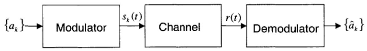
Figure 2-1: Simplified Digital Communication System
Figure 2-1 represents a simplified block diagram of a digital communication sys-tem. The discrete information symbols, ak, are fed into the modulator, which converts the digital data into an analog waveform, Sk(t). The waveform is transmitted and passed through a channel, which adds noise to the analog signal. At the receiver, the demodulator processes the distorted signal, r(t), and produces an estimate of the
2.1.1
Modulation
The information symbols, ak, may take on any value in the discrete set {0, 1, ... , M
-1} with equal probability, where M is the cardinality of the information symbol set. The modulator maps each symbol into a distinct waveform in the set S =
{
so(t), si(t),..., sM-1(t)}. The selected signal, Sk(t), is sent over the channel, asshown in Figure 2-1.
When the information symbols are binary digits taking on values in the set {0, 1}, they are called bits, and binary modulation, such as antipodal signaling or binary phase shift keying (BPSK), is used. In this situation, the modulator maps the {O, 1} symbol set into the signal set {s(t), -s(t)}, respectively [6]. Throughout this thesis,
we will assume BPSK modulation.
2.1.2
AWGN Channel
The most common type of channel assumed in digital communication systems is the Additive White Gaussian Noise (AWGN) channel, shown in Figure 2-2. In this model, the channel response is assumed to have no distortion and the only signal degradation is due to the presence of the thermal noise, n(t), generated by the receiver antenna and front-end electronics [12]. Furthermore, the noise is assumed to be independent of the transmitted signal.
Channel
Sk (t) + -+r(t)
n(t)
Figure 2-2: Additive White Gaussian Noise (AWGN) Channel
The additive white Gaussian noise, n(t), is a sample function of the AWGN pro-cess, N(t). A random process can be well-modeled as a white-noise process as long as it has a flat power spectral density (PSD) within the occupied frequencies, B, of
the system of interest, and the noise outside of B is independent of the noise within
B [13]. Explicitly, any process, w(t), with a PSD, Sww(f), that is flat within the bandwidth of interest and is independent of the noise outside the bandwidth, i.e.
SWW(f) - C2, IfI < B (2.1)
where B is the bandwidth, acts as a white-noise process for the system and can thus be replaced by the ideal white-noise model
S..(f) = 2 (2.2)
and
R, (T) = Ur26(T), (2.3)
where R., is the autocorrelation function of the noise.
A continuous-time stochastic process x(t) is defined to be a Gaussian process
when, for all choices of the deterministic function a(t), the scalar
z = f a(t)x(t)dt (2.4)
is a Gaussian random variable with a probability density of the form 1 -m
Pz(z) = 2iU2 e (2.5)
where m is the mean, and o2 is the variance [13].
2.1.3
Detection
As shown in Figure 2-1, the transmitter sends a waveform, Sk(t), from a set of
wave-forms, S, known at both the transmitter and receiver. At the receiver, the objective is to detect the transmitted waveform. The optimum detection technique that minimizes the probability of error, assuming an equiprobable signal set, is maximum-likelihood detection. This detector can be implemented using a matched-filter or correlator receiver, as shown in Figures 2-3 and 2-4, respectively [13].
-- +so (T -t) --+s, (T -t) t=T Choose r(t) -Maximum - 00SmI-1(T - t)
Figure 2-3: Matched-filter realization of the AWGN optimum detection rule where each filter is matched to a signal from the signal set, S. Following the filter is a sampler that produces the sufficient statistic, defined as all the information necessary to produce a minimum-probability-of-error decision. The result of the sampler is then fed into a decision device that chooses the transmitted signal as the one with the maximum sufficient statistic.
The correlator receiver, seen in Figure 2-4, is an equivalent optimum detector, but the received signal is now correlated with the basis functions of the signal set, S, where each signal in S can be expressed as
L
Sk(t) ~ Zojk OP(t) (2.6)
j=1
where {O(t)} are the L basis functions, L < M, and ajk is the result of projecting Sk(t) onto O5(t).
When BPSK modulation is used, the signal set includes s(t) and -s(t). Assuming an AWGN channel, as in Figure 2-2, the received signal is
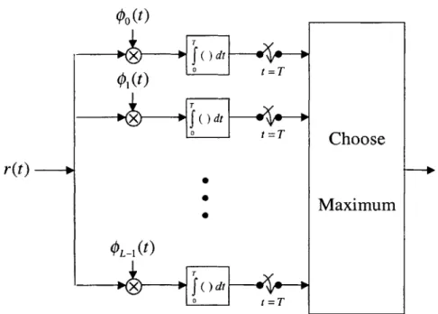
00tW X ~dt-W X f dt tT Choose r(t) --Maximum OL1(t) T ) dt 0 t T
Figure 2-4: Correlator realization of the AWGN optimum detection rule where Sk(t) E
{
Ess(t), -f'E s(t)} and n(t) is a sample function of a zero-mean AWGN process with San(f) equal to a'. The signal energy of the transmittedwave-forms is E, = fj s!(t)dt, where we have assumed that the signals are normalized
to unit energy, so that f s2(t)dt = 1. According to Figure 2-4, the received signal
should be projected onto the basis set. In the BPSK case, there is only one basis and thus, it suffices to correlate r(t) with s(t), which results in the sufficient statistic
y = f6r(t)s(t)dt
=
f
0 Sk(t)s(t)dt +f6
n(t)s(t)dt (2.8)Sk+fl
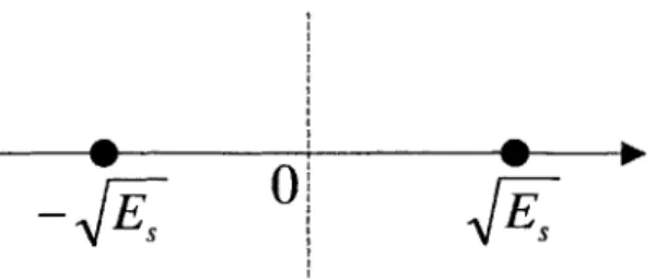
where the signal component is Sk E {V/E , -V'E } and n is a zero-mean Gaussian random variable with variance a2. The discrete-time signal constellation is thus
{v/ET,
-VE-}, and can be seen graphically in Figure 2-5.From Figure 2-5, we observe that the optimum decision boundary occurs halfway between the points at zero. Thus, the probability of error, defined as the probability of deciding upon the wrong transmitted waveform, is the probability that the noise
_
0!
Figure 2-5: BPSK Discrete-Time Signal Constellation value exceeds V/E5. More formally,
P (E) =- In > ~]=Q
(
)(2.9)
where the Q-function is defined as the tail probability of a normal Gaussian distribu-tion,
Q(x)
= e- 2/2dt. (2.10)2.1.4
Single-User Bound
In the previous section, we derived the probability of error for a single user commu-nicating a BPSK-modulated signal. Because the information symbols are bits, the symbol energy, Es, is equal to the bit energy, Eb. Assuming an AWGN process of power spectral density N0
/2,
the probability of error from (2.9) becomes2Es
P(E) = Q (2.11)
where the quantity I is called the signal-to-noise ratio (SNR) per bit. The above probability of error expression is also called the single-user bound and serves as a useful measure of comparison against detection in a multiuser communication system, as will be seen in subsequent chapters.
2.2
Multiuser
Communication
Multiuser communication refers to the case in which several users share a common channel. There are several ways for users to share a channel, and one type of mul-tiuser communication is a multiple access communication system, in which several users transmit over a common channel. Multiple access methods are the basis for wireless communication networks, such as satellite, cellular, and mobile communica-tion networks [5]. A common example of multiple access communication from today's
society is cellular telephones communication with a base station [10]. The received signal at the base station is a superposition of the users' signals distorted by noise. The main objective of the receiver is to approximate with low probability of error the information message transmitted by each user.
2.2.1
Multiple Access Communication
The three most popular multiple access methods for multiuser communication are time-division multiple access (TDMA), frequency-division multiple access (FDMA), and code-division multiple access (CDMA).
Orthogonal Techniques: TDMA and FDMA
In TDMA, the frame duration, T, is divided into N non-overlapping time slots of duration T/N each. Each user wishing to transmit is assigned to a particular time slot within each frame, and because there are N time slots, the system can accommodate up to N users. Here, the users take turns transmitting and do not interfere with each other.
A similar method is FDMA, where the available channel bandwidth, F, is divided
into N non-overlapping subchannels of bandwidth F/N each. Again, each user is assigned a subchannel in frequency on which to transmit. Because the users are non-interfering in frequency, the system can support up to N simultaneous transmissions.
Non-orthogonal Technique: CDMA
We observe that in the orthogonal multiple-access methods, TDMA and FDMA, the channel is partitioned into independent single-user subchannels. Thus, under ideal assumptions of zero inter-symbol interference (ISI) and no nonlinearities, the subchannels are mutually orthogonal and there is no interference among the users. Subsequently, each user's transmitted signal is detected independently from the rest. Alternatively, in CDMA, the signal transmissions among the multiple users overlap completely both in time and frequency. Direct-sequence CDMA is obtained by mul-tiplying each user's data signal by a distinct signature sequence. The multiplication
by the signature sequence has the effect of spreading each user's signal over the entire
available frequency spectrum, which is why CDMA is also known as spread-spectrum multiple access. The signature sequences assigned to each user are not orthogonal, and thus, the users' signals are correlated. Therefore, CDMA is a non-orthogonal multiple access technique for which the detection techniques discussed above must be revised.
2.2.2
Advantages of CDMA
Spread-spectrum communication techniques have many beneficial characteristics. Some advantages of CDMA, such as privacy and frequency reuse, are discussed below.
In spread-spectrum communication, each user is assigned a unique code that spreads that user's signal over the total available bandwidth. The result of the spreading is a decrease in the power spectral density, making the user's signal hidden in noise. Additionally, the pseudorandom properties of the signature codes make the user's signal appear as noise, making it even harder to detect without knowledge of the signature sequence. The spreading allows the users to remain undetectable and thus, introduces a privacy aspect not present in non-spread-spectrum methods [4].
In a cellular wireless system, the terrestrial area is theoretically divided into hexag-onal shapes, called cells. Each cell has a base station which receives and decodes the information transmitted by users in that cell. In orthogonal multiple access tech-niques, such as TDMA and FDMA, the users in adjacent cells must be provided
disjoint slots, which is achieved by allowing each cell communication on a different frequency band. This leads to limited frequency reuse, where typically, a frequency slot is reused only once every seventh cell. Additionally, frequency plan revision and user channel reallocation are required every time a new cell is introduced. With a spread-spectrum technique, such as CDMA, universal frequency reuse applies not only to users in the same cell, but also to those in all other cells. The channel allocation problem is also alleviated [11].
2.3
The Code-Division Multiple-Access Channel
2.3.1
Basic Synchronous CDMA Model
In a wireless cellular communication system, users within a cell are transmitting to one base station, thus, sharing the same channel. In practice, CDMA users are asynchronous. To ease the mathematical analysis of asynchronous systems, it is common practice to model the users as synchronous. The analysis of a synchronous system later simplifies the extension to asynchronization. In [10], it is shown that K asynchronous users sending a stream of 2M + 1 bits can be modeled as (2M + 1)K users, each transmitting one bit. Thus, even though on the uplink, where the users transmit to the base station asynchronously, we represent them in a synchronous communication model.
Multiple-access techniques using orthogonal codes yield the best performance for synchronous systems, such as the downlink in cellular communication systems, where the base station broadcasts the superposition of the users' signals simultaneously. The synchronization guarantees orthogonality among the users' signals. For asynchronous systems, however, the use of orthogonal spreading codes degrades performance sig-nificantly. This is due to the fact that orthogonality is not maintained between time-shifted versions of the signals, resulting in the possibility of high cross-correlation among these asynchronous signals. Thus, in asynchronous systems, it is beneficial to use spreading sequences which are not necessarily orthogonal, but instead have low cross-correlation values.
We assume the synchronous CDMA model with antipodal modulation adopted from [10], where the received signal at time t is given by:
K
r(t) I= Akbksk(t) + n(t), t E [0, T] (2.12) k=1
where
" T is the symbol interval in seconds
" K is the number of users
* Sk(t) is the signature waveform assigned to the kth user
* Ak is the path gain of user k
" bk E {-1, +1} is the bit transmitted by the kth user
" n(t) is a zero-mean complex Additive White Gaussian Noise (AWGN) process
with a power spectral density of N0
/2
per dimension.2.3.2
Signature Waveforms
Each user is assigned a unique signature waveform, which is the "code" in CDMA that distinguishes each user from the rest. The unique signature waveforms assigned to each user, known to the transmitter and receiver, are normalized to unit energy
kt
sk(t) 12-
f
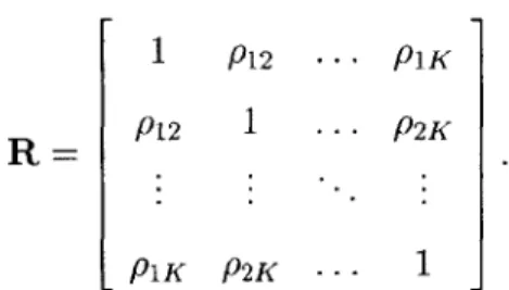
s (t)dt = 1 (2.13)and have cross-correlation given by
ST
Pij = (si, s) = Zsi(t)sj (t)dt (2.14)
where pij = pji, 1 < i, j < K.
1 P12 --- P1K
R P12 1 .. P2K (2.15)
PIK P2K - 1
2.3.3
Discrete-Time Synchronous Model
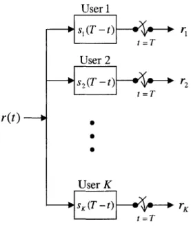
In most communication systems, detection and decisions are not made on the continuous-time received signal, r(t), but rather on the discrete-time vector, r. This continuous-to-discrete time conversion can be achieved by a bank of filters, where each filter is matched to a different signature waveform, as shown in Figure
User 1 --- s(T - t) r t =T User 2 S 2(Tt) r2 t =T r(t ) User K t =T
Figure 2-6: Matched-Filter Bank
For any vector x, let xT denote the transpose of x. We can now write (2.12) in
vector form given by
r = RAb + n (2.16)
A = diag([A,, A2, -- ,AK]) (2.17)
b =[bib2,- --bK T(2.18)
n n,, n2, , nK T2.19) r rir2, . , rK T(2.20)
and the rks are the result of passing r(t) through the bank of filters in Figure 2-6. The output of the matched filter for the kth user is
ST
rk r(t)Sk(t)dt(2.21)
= Akbk +E Ajb pik + nk
j#k
where the middle term represents the multiple-access interference (MAI) and the noise quantities, nk, are samples of a complex Gaussian random variable with mean zero, variance N0/2 per dimension, and covariance matrix NR. We observe that the
output of each matched filter contains information about every other user's signal in the form of the MAI. Thus, it makes sense to perform joint decoding of the users' signals using all of the sufficient statistics for detection of all users. This topic of multiuser detection will be discussed in the next chapter.
2.3.4
Fading
In a classical communication system, the main signal degradation is due to the ther-mal noise. In a wireless environment, however, additional degradation exists due to multipath fading. The term fading is used to describe the amplitude fluctuation of a radio signal over some period of time or travel distance. Multipath fading refers to the situation when two or more versions of the transmitted signal arrive at the receiver with different amplitudes and phases. The effect of multipath fading is due to the presence of reflecting objects and scatterers in the channel. These effects result
in multiple versions of the transmitted signal that arrive at the receiver antenna at
slightly different times. The random phases and amplitudes of the different multipath
Throughout this thesis, we will assume frequency-flat fading, which affects the received amplitudes but does not introduce signature waveform distortion. Addition-ally, the spectral characteristics of the transmitted signal are preserved at the receiver, even though the strength of the received signal changes with time due to fluctuations in the gain of the channel caused by the multipath [8]. The phase and amplitude fluctuations in the signal translate to modeling the path gains, {Ak}, in (2.12) as time-varying coefficients with a certain probability distribution [10]. When the path gain for each user, Ak, is modeled as a zero-mean complex-valued Gaussian process, the envelope, Ck = jAkj, at any instant in time takes on a Rayleigh distribution
fc, (ck) =ckek/2 (2.22)
which is frequently used to describe the non-line-of-sight paths common in a mobile wireless environment.
2.4
Summary
In this chapter, we presented a brief background of communication theory. We saw that single-user communication theory can be applied to multiuser communication systems that employ orthogonal multiple-access techniques. In CDMA, the cross-correlations of the signature sequences are non-zero and thus, the transmission signals are not orthogonal, resulting in multiple-access interference among the users. Due to the presence of the MAI, the optimal detection techniques of TDMA and FDMA systems are no longer optimal and multiuser detectors in the presence of MAI must be investigated.
Chapter 3
Multiuser Detection
In the previous chapter, we introduced the CDMA channel and showed that the sufficient statistic is the discrete-time vector of matched-filter outputs
r = RAb + n (3.1) where R is the correlation matrix of the signature sequences, A is the channel
ma-trix, b is the vector of transmitted bits, and n is a zero-mean Gaussian noise vector with covariance matrix NR. Assuming perfect channel estimation and thus, perfect knowledge of the channel coefficients, {Ak}, the objective of the receiver is to detect with low probability of error the transmitted sequence of bits, b. In this chapter, we describe multiuser detection techniques, including the optimum detector and several suboptimal linear detectors.
3.1
The Optimum Multiuser Detector
The optimum receiver for synchronous CDMA, developed by Verdu, exploits the structure of the MAI and is defined as the receiver that selects the most probable sequence of bits given the received signal [10]. The optimum detection rule under equiprobable hypotheses is the Maximum-Likelihood (ML) rule, which is equivalent to the minimum-distance rule for the Additive White Gaussian Noise (AWGN) chan-nel. Jointly optimum decisions are obtained by a Maximum-Likelihood Sequence Estimator (MLSE) that selects the most likely sequence of transmitted bits by all of the users given the received sequence.
In detecting the transmitted bits, all possible noise-free received vectors are cal-culated. The vector that has the smallest distance to the actual received vector is chosen as the most likely transmitted sequence of bits. For the K-user synchronous system with antipodal modulation, each user transmits either +1 or -1 during each time slot. Thus, there are 2K different possible transmitted bits at each time slot.
It is obvious that for a large number of users, the complexity is enormous. Conse-quently, the optimum multiuser detector is unrealizable for most practical applica-tions. This inefficiency of the optimum detector has motivated researchers to develop less computationally-intensive suboptimum receivers.
3.2
Suboptimum Linear Detectors
3.2.1
Conventional Single-User Detector
In conventional single-user detection, the received signal is passed through a bank of filters, where each filter is matched to each of the signature sequences of the users, to obtain the discrete-time data shown in (3.1) . The outputs of the matched-filter bank are passed to the decision device, where estimates of the transmitted bits are made independently for each user. A block diagram of the conventional detector is shown in Figure 3-1.
From 2.3.3, we know that the output of the matched filter for the kth user is
IT
rk r(t)sk(t)dt(3.2)
= Akbk +E Abipik +nk.
j:Ak
It is clear that the middle term, which is the MAI, is what distinguishes the multiple user case from that of the single user. If the signature waveforms are orthogonal, then the cross-correlation is zero and the MAI disappears, making the conventional single-user detector the optimum solution. That is not the case in CDMA, where the waveforms are correlated for the reasons mentioned in Section 2.3.1; thus, the single-user detector simply ignores the MAI when applied to multiuser detection.
User I s, (T - t) r r =T User 2 s2(T -t) r2 t =T r(t) -+ User K SK ( ~ -t K =T
Figure 3-1: Conventional Detector
is received at the same power, the conventional detector performance is tolerable. The advantage of this detector is that the complexity grows linearly with the number of users. The disadvantage comes in when there is fading and the users' received power levels are not equal. Even though the correlation coefficient may be low, an interferer whose power level is strong relative to other users has the ability to drown out other low-power users. This situation is called the near-far problem in multiuser communication and requires power control to be used if the conventional single-user detection is to be employed [5].
It is worthwhile to note that for some time, the single-user matched filter has been considered to be almost optimal for channels with a large number of equal-power users. If we consider, again, the second term in equation (3.2), we can say that it can be accurately approximated by a Gaussian random variable using the Central Limit Theorem if K is sufficiently large. Then, the problem reduces to detection in an AWGN channel, and the conventional detector is optimal. This is true, in fact, if we assume that the receiver for user k has access to rk only. However, if the receiver
is allowed to look over all outputs of the matched-filer bank to detect bk, then using
3.2.2
Decorrelating Detector
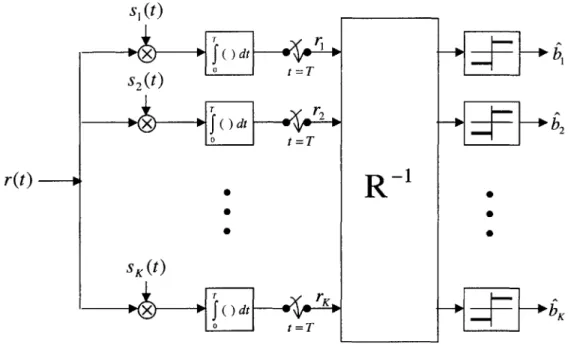
One property that makes the conventional detector unattractive is its inability to detect users with unequal received powers without some type of power control. The decorrelating detector completely cancels the interference of other users, yet has the linear-growth complexity property of the conventional detector.
To motivate the decorrelating detector, lets first assume that the signals are re-ceived noise-free. Thus, the rere-ceived signal is
r = RAb. (3.3)
If the signature sequences and thus, the columns of R, are linearly independent, then
RR, is invertible. We can obtain the transmitted bits perfectly without knowledge
of the received amplitudes, {Ak}, by multiplying the sufficient statistic vector by the
inverse of R, so that
R-'r = Ab. (3.4) We have completely decorrelated the users and now, we can do a simple sign decision to obtain the bit estimates, b [10].
Returning to the original model and including the noise yields
R-r = Ab + R-'n (3.5)
and the estimate of the transmitted bits becomes
b = sgn (R-r) (3.6)
as shown in Figure 3-2. We observe that each user is still free from interference caused
by any of the other users and is only distorted by the noise due to R-1n. However,
the new noise vector now has a covariance matrix R-1 as opposed to -R before
the processing. Because of the structure of R, the diagonal values of R 1 are higher
than those of R, and thus, the new covariance matrix actually enhances the noise. Thus, in some situations, other suboptimal linear detectors may perform better than the decorrelator detector.
s,(t)
x
TT s2(t x dt o t=T r(t) SK (t) s r f dt t o t=T +b2 - 0Figure 3-2: Decorrelating Detector
3.2.3
Minimum Mean- Square-Error Detector
When the received signal amplitudes are unknown, the decorrelating detector is a sensible choice, as seen in the previous section. To counteract the noise enhance-ment problem of the decorrelating detector, we can obtain another detector so as to minimize the mean-square error (MSE). We seek a linear transformation, Tr, where matrix T is the one that minimizes the MSE
J(b) = E [(b - Tr)T(b - Tr)] . (3.7)
The result of the minimization yields
T =
(R±
Io (3.8)and thus, the output of the detector becomes
S= sgn [(R + N) r] . (3.9)
MMSE detector, as well as other detectors discussed in this chapter, is presented in
the next section.
sK(t)
x
f
t
--- b0 *2 t = 2W
X fdt
-Figure 3-3: Minimum Mean-Square Error (MMSE) Detector
3.3
Summary
In this chapter, we introduced the concept of multiuser detection, which is a
joint
decoding technique for DS-CDMA users. The optimum multiuser detector is the MLSE and yields the best possible performance; however, it is too complex to be implemented in practice. The implementation in today's systems are the conventional single-user matched filter receivers, which offer the least complexity. However, the performance of the single-user matched filter is inadequate for data communication systems and its susceptibility to the near-far problem may cause further degradation. The decorrelator detector completely cancels the multiple-access interference, but causes noise enhancement. The MMSE detector minimizes the mean-square error
between the estimated and actual transmitted bits, but still leaves some multiuser
Figure 3-4 shows the performance curves of the detectors for 4 users with cross-correlation matrix 1 -0.25 -0.25 -0.25 -0.25 1 -0.25 -0.25 R = . (3.10) -0.25 -0.25 1 -0.25 --0.25 -0.25 -0.25 1
The horizontal axis is the signal-to-noise ratio (SNR) in decibels (dB), and the vertical axis represents the bit-error-rate (BER). Although the decorrelator and the MMSE detectors outperform the conventional single-user detector, there is still a gap between the linear detectors and the optimum MLSE. This gap leaves a lot of room for studying the tradeoffs between performance and complexity of multiuser detectors.
4 users, p=-0.25
10 - 10 ...-.-- -0- Single-user BoundMLSE -*--. MMSE .- Decorrelator --- Matched Filter 10-10 - . ... 0 1 2 3 4 5 6 7 8 9 10 Eb/NO (db)
Chapter 4
The Channel-Shortening Multiuser
Detector
In the last chapter, we presented some well-known multiuser detectors, including the optimum maximum-likelihood sequence estimator, as well as some suboptimal linear multiuser detectors. We showed that the decorrelator detector and the MMSE de-tector perform better than the matched-filter dede-tector with reasonable complexity; however, their performance is still far from the optimum MLSE, which is too complex to be implemented for realistic applications. In this chapter, we investigate the trade-offs between performance and complexity and develop a group detector that performs close to optimum but with a manageable complexity.
4.1
The Communication Model
We assume the synchronous CDMA model with antipodal modulation adopted from
[10] and described in section 2.3.1. We reiterate its key features here for convenience.
The received signal at time t is given by:
K
r(t) =
3
Akbksk (t) + n(t), t E [0, T] (4.1)k=1
where
" T is the symbol interval in seconds
* Sk(t) is the signature waveform assigned to the kth user " Ak is the path gain of user k
* bk E {-1, +1} is the bit transmitted by the kth user
" n(t) is a zero-mean complex Additive White Gaussian Noise (AWGN) process
with a power spectral density of N0
/2
per dimension.We assume perfect channel estimation, so that the receiver has full knowledge of the path gains, {Ak}. The discrete-time synchronous CDMA model from Section
2.3.3 is r = RAb + n (4.2) where A = diag([Al, A2,- -.,AK) (4-3) b =[b, b2, - ,bK ]T(4.4) n =[i, n2, ... , nKT (4.5) r=[rl,r 2,...,rK (4.6)
The discrete-time vector, r, forms a sufficient statistic for the detection of the users.
4.2
Problem Formulation and Derivation
The system model has K mutually interfering users and thus, we can say that the multiuser channel has K taps. The optimum multiuser detector, the MLSE, finds the most likely sequence of bits transmitted by the K users given an observation, r, with complexity of 2 K. However, for large K, the MLSE is too computationally complex
to be implemented in practice.
The multiuser detector developed in this research is composed of two steps, as shown in Figure 4-1. First, the channel memory is reduced from K to L by the application of a linear channel-shortening technique to the received vector, r. This
s1(t)
x
J()dt s2(t f dt 0 t T 0 S2 W SK (t ) dt x = ' Channel Shorteningw
M
L
S
B
G U"DFigure 4-1: Channel-Shortening Multiuser Detector
technique makes it appear as if there were only L users in the initial system by suppressing the other K - L users. In the second step, the result is fed into the
optimum detector, which performs MLSE on the output of the shortened channel. Consequently, the decoding complexity is reduced from 2 K to approximately 2L, L
<
K.The idea of channel shortening for multiuser detection was inspired by the im-pulse response shortening technique developed by Al-Dhahir and Cioffi in [1, 2] for equalization in Digital Subscriber Lines (DSL). However, the following mathematical derivation of the channel-shortening multiuser detector differs significantly from that of the equalizing channel-shortening technique.
We define the K x K channel matrix, 9 = RA, to have the following structure:
A12 A2,12 A2 A1p1K A2P2K ... AKP1K ... AKP2K ... AK (4.7)
[4t-Q =The received vector from (4.2) now becomes
r = Ob + n. (4.8)
We wish to shorten the K-tap multiuser channel to L taps in order to detect the bits transmitted by a subset of L users from the set of K users. We call the subset of users to be detected and suppressed UD and Us, respectively. Next, we define a weighting vector
wT = [W 1 w2 ... WK} (4.9)
which will multiply r to achieve the channel shortening. We assign the columns of Q
to be
Q, A, [1 P12 ... PIK]T
2 = A2 [P12 1 ... P2K] (4.10)
QK = AK [P1K P2K ... .
Applying the weighting vector to the observation vector results in K
wTr = wT ibi + wTn. (4.11)
We now want to maximize the Signal-to-Interference-and-Noise Ratio (SINR), where the signal power refers to the power contributions of the users in UD, and the interference-plus-noise power refers to the power contributions of users in Us and the noise, n. This condition results in the following optimization problem
Z
wT(RQ7QT)W
ww w
W (jq + NoR w
jEUs
where i and j are mutually exclusive. Denoting the signal power as C = f2, f2T
iEUD NO
and the noise-plus-interference power as B = ZT + R, the maximization of
(4.12) becomes
wTCw
max
wTBw (4.13)
This maximization problem is equivalent to maximizing wTCw while keeping wTBw constant. Applying the Cholesky factorization to matrix B, we obtain its square root matrix, F, such that
B = F TF. (4.14) Consequently, the denominator of (4.13) becomes
WTBw = WTFTFw
= VT
(4.15) (4.16) where v = Fw, and (4.12) can now be written as
vT(F-1)TCF-lv
max
y vTv (4.17)
The optimization problem of (4.13) has been reformulated to maximizing vT(F 1 )T CF-1v
subject to the constraint vTv = c, where c is some constant. We now apply the
La-grange multiplier to obtain
L(v) = vT(F- 1)TCF-lv + A(c - vTv)
Taking the partial derivate with respect to v and setting it to zero yields
'L(v) = 2vT(F )T CFlv - 2AvT (vT(F-)TCF-1 (F 1)TCF-lv - 0 = AvT)T = Av (4.18) where v and A are the eigenvector and eigenvalue, respectively, of (F 1)TCF-1.
Substituting (4.18) into the numerator of (4.17) transforms the maximization equation of (4.12) into
wTCw - vAv A
=Tw- ~ = A (4.19)
WTBw VTV
In order to maximize the above expression, we must choose v to be the eigenvector corresponding to the largest eigenvalue of (F-1)TCF-'. Because we want to perform optimum detection on the L users of the shortened channel using MLSE, we must have L observations coming out of the channel shortening. Therefore, we select vi, 1 < i < L, to be the L eigenvectors corresponding to the highest L eigenvalues of (F-1)TCF-l, counting multiplicities. The weighting matrix W in Figure 4-1 now becomes wT WT W = 2 (4.20) T LWL where wi = F-1vi, 1 < i < L. (4.21)
The task of choosing the group of users to detect, UD, is not a trivial one and adds a level of optimization to the above problem. However, when the cross-correlations of the signature waveforms are equal, pij = p when i 74 j, the problem becomes easy. From here on, we will assume that the signature waveforms have equal cross-correlation values.
In the equipower scenario, the users are received at the same power, and any com-bination of L users can be selected to be in UD. In the case of a fading channel, where the users' received powers are not necessarily equal, the users are detected according to the received power, with the L highest-power users detected first. Following the detection of the L users, we perform successive interference cancellation to cancel the MAI inflicted by the L users onto the rest of the K - L users not yet detected.
Then, we recompute the variables used in the optimization and apply the channel shortening to the next L users. This procedure is repeated until all users have been
detected.
Using the multiuser detection scheme described in this chapter, a group of L users are jointly detected using the MLSE with a complexity of 2L. Since there are K
users, the channel-shortening multiuser detection procedure will be employed K/L times, with a groups of L users being detected each time. We ignore the complexities associated with Cholesky factorization and triangular matrix inversion since they are negligible compared to the complexity of the MLSE. Thus, under the assumption that the signature waveforms have equal cross-correlation values, the channel-shortening detector has complexity ; 2L, L < K, which is a significant reduction over the 2K
Chapter 5
Simulation Results
We now present simulation results showing the performance, in terms of
bit-error-rate (BER), of the channel-shortening detector derived in Chapter 4. We compare
the performance of this detector to the multiuser detectors described in Chapter 3. We model the equipower case, when the users' received signals are assumed to have equal power. The path gains, Ak, are set to 0.5 + j0.5, where j = /-1. Figure 5-1 shows the performance of the 4-user system mentioned in Section 3.3, where the users
are received at equal powers and the cross-correlation matrix is
1 -0.25 -0.25 -0.25
-0.25 1 -0.25 -0.25
R0= (5.1)
-0.25 -0.25 1 -0.25 --0.25 --0.25 -0.25 1
As we observe from the BER plot, shortening the multiuser channel achieves im-provement in performance over the linear multiuser detectors. It is not surprising that the shortened two-tap channel yields a better performance than the shortened one-tap channel. The more taps that we keep in the channel, the better the perfor-mance will be. This makes sense because we never completely cancel the multiple access interference; therefore, by performing multiuser detection on users within the
group, we are not utilizing all of the information contained in the data of users out-side of the group. The more taps, or users, that we keep in the channel, the more information we keep, and thus, performance improves as the number of taps in the
4 users, p=-0.25 10-10... . ... . 10 -4 . . 10 --$- Single-User Bound-- MLSE - - - - -
--s-- Channel Shortening: 2 taps
10-A- Channel Shortening: 1 tap
-*- MMSE -e- Decorrelator - - Matched Filter 1 0 ~ .... .. .. ... N 0 1 2 3 4 5 6 7 8 9 10 Eb/NO (dB)
Figure 5-1: Multiuser Detectors Performance for 4 equipower users
shortened channel increases. If all K taps are kept, the channel-shortening detector is equivalent to the MLSE.
Next, we examine the performance of a 15-user system. The cross-correlation matrix has the form of (2.15) with Pzj = -1/15, 1 i, j 15, i #L
j.
Figure 5-2 shows the performance when 15 equipower users are detected three at a time using the channel-shortening detector. We observe a significant improvement in performance over the conventional matched-filter detector.Figure 5-3 shows the performance of the channel-shortening multiuser when 15
users are communicating over a Rayleigh fading channel. In the Rayleigh fading case,
the signals transmitted from different users undergo independent fades, and the path gains are modeled as samples of independent complex Gaussian random variables with mean zero and variance 0.5 per dimension. We assume quasi-static fading in which the Aks are constant during a frame of 100 bits and vary from frame to frame.
15 users, shortened to 3 taps, p=-1/15 10-1 102 10-3 Lu 104 0 6 7 8 9 10
Figure 5-2: Multiuser Detectors Performance for 15 equipower users
Following the channel shortening, we detect three users at a time using successive interference cancellation, and once again, observe a considerable gain in performance over the conventional matched-filter detector.
For the 15-user system described above, the channel is shortened to three taps, yielding a decoding complexity of approximately 5 -2' versus the 215 complexity of the MLSE detector. We note the tradeoff between complexity and performance of the channel-shortening multiuser detector. If we keep all K taps in the channel by letting UD = {1, 2, - - -, K}, the channel-shortening detector becomes the MLSE, and
we achieve optimum performance with 2K complexity. As we decrease the number of
taps we keep in the channel, complexity decreases at the expense of performance. If we shorten the channel to one tap, the channel-shortening group detector becomes linear, with a complexity of K. However, the performance is better than the decorrelator and the MMSE detectors, as shown in Figure 5-1. It is interesting to point out
. . . . . . . . . . . . . . .. . . . . . . .. . .. . . . . . . . . . . ... . . . .
.... ... .... ... - ... ' ... ... ... ...... Single- User Bound ... . .. .. ....- ... . ... ... ... I ... . .... . ... ... ... ... C ha n ne l S ho rte n ing ... ... Matched Filter ... ... . .. ... ... ... ... ... .. ... ... ... ... .... .. ... .... .. .......7 ... ... ... ... . ... ...I .. ... ... ... ... ... ... . ... .... ... ... ... ...: ... .... ... ... .... ...I ... .. ... ... * ... ... ... . ... .. ... .... ... ... .. ... ... . ... ... ... ... ... ...: : : . . .... ... ... ... ... ... ... ... ... .. . . ... ... ... ... ...I ... ... .. ...I .. ... ... ... ... ... .... ... ... ... ... .... ... .... ... . ... ...I .. ... .... ... ...I ... ...I ... ..I ... ... . ...I ... ... ... ... ... ... ... ... ... .. ... .. .. .... . ... .. ... . ... .. . ... .. .. .... ... . . .. . ... .... . .. .. .. .... . ... ... ... .. .. ... . .'. . . . ... ... .. ... .. ... .. ... ... ... .. ... 7 ... . ... ... .. .. .: ... . ... .... . ... .. . ... .. ... .. ... .. .. ... ... .. .... .. . .. . ... .. ... .. ... .. ... . .... ... ... . ... .. .. . . . . . . . . . . .. ... .. .. .. .. .. ... .. ... . ... .. .. ... . ... .. ... . ... .... ... .. .. ... .... . ... .. . ... .. ...I . ... .. ... ... .. . .. .... .. ... .. .... . .. . . .. ... . ... .. .. ... . ... .... .. .. .. ... .... . ... .. .. . .. .. ... ... .. .. .. .. .. ... .. .. .. ... .. ... .. ... . . .. ... .. .... ... .. . ... .. .. ... .. . .. .. ... .. .. ... .. ... .. .. .. .. ... .. .... . ... .. ... .. ... .. ... . ... .. . ... ... . .. .... . ... .. .. ... .. ... .. ... .. ... ... . . ... ..I . .. ... : : : 7: . .. .. .. .. ... ... . .. ..1 : : :.: : : : : : : : : :': : : : : : : : :': : : : : : : : :': : : : : : : :' : : : : : : : : : " : : : : .. . -... .. .. .. .. .. .. -... -.... . .. ... ... . ... .. .. .: .. ... .... .: . .. .. ... ..: .. ... .. . .. ... .. .1: .. ... ... .I .. .. .. .. .. ... ... . .. ... .. ... . .. .. ... . ... ... ... .. .. .. .... . .. .. .. .. ... ... .. ... . ... .. .. .-. .-..-..-. .-..-. .-..-..-..-. .-..-..-. .-..-. .-..-. .-..-. .-. ... .. .. .. ... ... .. .. ... ... .. ... . .. .. ... . . . .. .. ... .. .. .. ... .. ... ..I .. .. ... .. ... .... ... .. .. .. ... . ... .. . ... .. .. ... .. ... .. .. ... .. ... ... .. .. .. ... .. .. . . . . .. . . ... . . . ... . . . ... . . . ... . . . .. . . .. . . . .. .. ... .... . .. ... .. ... . ... . .. ... ... .... .. ... . ... .. .. ... .. .. .. .. ... .. .. ... .. ... ... .. ... ... 1 2 3 4 5 Eb/No (dB)
15 users, shortened to 3 taps, p=-1/15 -- Single-User Bound -- Channel Shortening -+- Matched Filter 10- .. - . - - - -0 1 2 3 4 5 Eb/No (dB) 6 9 10
Figure 5-3: Multiuser Detectors Performance for 15 users in a Rayleigh Fading Chan-nel
that shortening the channel to two taps yields a complexity of 2 = K. Thus, by shortening the channel to two taps instead of one, we obtain an improvement in performance while maintaining the linearity of the detector.
Chapter 6
Conclusions and Future Work
This thesis presented a background of multiuser detection theory and derived a channel-shortening multiuser detector for wireless communication systems. This chapter summarizes the research results and provides a framework for future work.
6.1
Summary
The area of multiuser detection has received a lot of attention from researchers during the past few years. Although the optimum detection scheme, the MLSE, has been known for a long time, its complexity prevented it from being an implementable detection technique in a system of many users. This problem of complexity motivated researchers to develop less complex multiuser detectors.
Two very common linear multiuser detectors are the decorrelator and the min-imum mean-square error detector. Although these two detectors outperform the conventional single-user matched-filter receiver, the gap between the linear detectors and the optimum detector encourages further investigation of the tradeoffs between performance and complexity of multiuser detection techniques.
In this thesis, we derived a channel-shortening technique that strengthens the presence of the group of users to be detected while suppressing both the interference of users outside the group and the noise. This technique was combined with the
MLSE to yield a multiuser detector that achieves near-optimum performance with
a significant decrease in complexity, under the assumption that the cross-correlation values of the users' signature waveforms are equal.
6.2
Future Work
In this research, we derived the channel-shortening matrix for the general case of the correlation matrix. The choice of the group of users to detect and the group to suppress, however, was made under the assumption that the signature sequences have equal cross-correlation values. An interesting problem is the determination of an efficient way to select the groups and their cardinalities when the correlation matrix is arbitrary. The optimal way to pick the group of users to detect is to perform an exhaustive search over all possible groups until the one that yields the highest Signal-to-Interference-and-Noise ratio is found. This method, however, has the same complexity problem as the MLSE, and is not likely to be an implementable solution. Intuition suggests to choose the most powerful, yet the least correlated users to detect as a group; however, a good solution with low complexity has not been found, and the selection of groups remains an open problem.
In this thesis, we did not investigate the effects of channel coding on the perfor-mance of the detectors. Additionally, we assumed perfect channel estimation, which yields knowledge of the channel matrix. An interesting possibility for future work is to extend the analysis of this thesis to asynchronous coded multiuser systems com-municating over a fast-varying channel.