HAL Id: tel-00348730
https://tel.archives-ouvertes.fr/tel-00348730
Submitted on 21 Dec 2008
HAL is a multi-disciplinary open access
archive for the deposit and dissemination of
sci-entific research documents, whether they are
pub-lished or not. The documents may come from
teaching and research institutions in France or
abroad, or from public or private research centers.
L’archive ouverte pluridisciplinaire HAL, est
destinée au dépôt et à la diffusion de documents
scientifiques de niveau recherche, publiés ou non,
émanant des établissements d’enseignement et de
recherche français ou étrangers, des laboratoires
publics ou privés.
Reduction of magnetic noise in PWM-supplied induction
machines - low-noise design rules and multi-objective
optimization
Jean Le Besnerais
To cite this version:
Jean Le Besnerais. Reduction of magnetic noise in PWM-supplied induction machines - low-noise
design rules and multi-objective optimization: Reduction of electromagnetic audible acoustic noise
and vibrations in electrical machines. Electric power. Ecole Centrale de Lille, 2008. English.
�tel-00348730�
Reduction of magnetic noise in PWM-supplied induction machines
− low-noise design rules and multi-objective optimisation
Jean LE BESNERAIS
Laboratoire d’Electricit´
e et d’Electronique de Puissance de Lille
Ecole Centrale de Lille
A thesis submitted for the degree of
Doctor of Philosophy in Electrical Engineering
20th of November, 2008
Rapporteurs M. Gabsi, Professeur, ENS Cachan (SATIE)
A. Miraoui, Professeur, Universit´e de Technologie de Belfort Montb´eliard (FCLAB)
Jury P. Brochet, Professeur, Ecole Centrale de Lille (L2EP)
M. Hecquet, Professeur, Ecole Centrale de Lille (L2EP)
V. Lanfranchi, Maˆıtre de Conf´erence, Universit´e de Technologie de Compi`egne (LEC) G. Friedrich, Professeur, Universit´e de Technologie de Compi`egne (LEC)
M. Bekemans, Docteur Ing´enieur, ALSTOM Transport A. Randria, Ing´enieur, ALSTOM Transport
Ce travail est d´edi´e `a mes parents qui m’ont soutenu tout au long de mes ´etudes, aux enseignants qui m’ont particuli`erement marqu´e, notamment Mr Varjab´edian et Mr Desfontaines (Lyc´ee Chˆatelet, Douai), Mr Mallet et Mr Sautet (Lyc´ee Wallon, Valenciennes), et Mr De Vuyst (Ecole
Centrale Paris), ainsi qu’`a Elise, sans qui rien de cela n’aurait ´et´e possible − tout comme tant
Remerciements
Les r´esultats de ce travail de th`ese sont avant tout issus d’une dynamique favorable entre le labora-toire d’Electrotechnique et d’Electronique de Puissance de Lille (L2EP), le Laboralabora-toire d’Electrom´e-canique de Compi`egne (LEC), et les entreprises ALSTOM et VIBRATEC, et je souhaiterais d’abord
remercier l’ensemble des personnes qui ont contribu´e `a cette synergie, et plus particuli`erement Pascal
Brochet, professeur `a l’Ecole Centrale de Lille et directeur de l’´equipe Optimisation du L2EP, et
Michel Hecquet, professeur `a l’Ecole Centrale de Lille, pour le montage de ce projet passionnant et
fructueux. Je suis entr´e dans cette th`ese en ayant de nombreuses id´ees re¸cues sur le g´enie ´electrique, aliment´ees par le peu de souvenirs qu’il me restait des travaux pratiques de classes pr´eparatoires ; j’en ressors avec un v´eritable enthousiasme et un vif int´erˆet pour la discipline, dont les concepts et les probl´ematiques de mod´elisation m’ont procur´e une importante satisfaction intellectuelle − `a tel point que j’esp`ere, apr`es deux ou trois ans d’exp´erience dans l’industrie, reprendre le m´etier de chercheur.
Je remercie ´egalement Pascal Brochet pour la confiance qu’il m’a accord´ee et la confortable ind´epen-dance qui en a r´esult´e, et lui suis reconnaissant de m’avoir confi´e une charge d’enseignement et de conseil aupr`es des projets des ´el`eves ing´enieurs, qui fˆut une exp´erience humaine tr`es enrichissante. Je le remercie aussi pour avoir su cr´eer au sein de son ´equipe une ambiance chaleureuse, propice
aux ´echanges tant personnels que scientifiques, et o`u travailler fˆut agr´eable. Je remercie au passage
l’ensemble des membres de l’´equipe (je pense en particulier `a Fr´ed´eric Gillon, St´ephane Brisset et
Xavier Margueron) pour leur accueil et leur accessibilit´e.
Je tiens `a remercier Michel Hecquet pour le suivi et l’organisation de mon travail de th`ese, et surtout
pour son dynamisme, sa bonne humeur et son ´ecoute. Ce fˆut un vrai plaisir de travailler avec lui, et
j’esp`ere que nous aurons encore `a collaborer apr`es la th`ese pour la r´edaction de nombreux articles.
Je remercie vivement Vincent Lanfranchi, maˆıtre de conf´erence `a l’Universit´e de Technologie de
Compi`egne (UTC), pour l’int´erˆet qu’il a port´e `a mon travail, pour son soutien et son immense
r´eactivit´e, plus particuli`erement lors de la r´edaction d’articles et lors de la r´edaction de th`ese, ainsi que pour les nombreuses discussions techniques qu’il a soulev´ees, et les id´ees qu’il a initi´ees en vue de r´esoudre de multiples probl`emes. Je le remercie ´egalement, ainsi que Guy Friedrich, professeur `a l’UTC et directeur du LEC, pour s’ˆetre associ´es de mani`ere aussi active au projet, et nous avoir prˆet´e leur mat´eriel de laboratoire qui nous aura permis d’enrichir consid´erablement notre compr´ehension des ph´enom`enes.
Je remercie aussi fortement Marc Bekemans (TCE Research Manager, ALSTOM-Charleroi), preuve vivante que l’on peut parfois faire plus de recherche en entreprise qu’en laboratoire, pour son suivi
particuli`erement technique, son profond sens physique et la pertinence de ses remarques qui ont donn´e naissance `a une partie des d´eveloppements plus th´eoriques de cette th`ese. Si je poursuis
ma carri`ere dans l’industrie, j’esp`ere pouvoir concilier `a sa mani`ere de hautes responsabilit´es en
Recherche et D´eveloppement, avec un niveau et une implication technique tout aussi importants. Je remercie au passage Anthony Leroy (ULB) dont le travail compl´ementaire sur le bruit des selfs et la psychoacoustique nous a ´et´e fort utile, tout comme les discussions qu’il a initi´ees. Je tiens ´egalement `
a remercier Sylvain R´ecorbet (ing´enieur acoustique, ALSTOM-Tarbes) pour sa gestion efficace et
agr´eable du projet PROSODIE, bien qu’il ait pris cette responsabilit´e alors que le projet avait d´ej`a
d´emarr´e.
Je remercie sinc`erement la soci´et´e VIBRATEC, notamment par le biais d’Eric Augis, de Gr´egory Lemaire et de Julien Berger, pour sa contribution dynamique et stimulante au projet, en d´epit mˆeme
d’un manque temporaire de moyens. Toutes nos rencontres ont ´et´e `a la fois chaleureuses et riches
en enseignements.
Je remercie ´egalement Andry Randria (Responsable Technique Nouveaux Projets R&D et Nouveaux Produits, ALSTOM-Ornans) pour la rapidit´e avec laquelle il a valid´e nos articles, et surtout pour
avoir r´eussi `a faire r´ealiser le premier des deux prototypes con¸cus lors de cette th`ese avant la
sou-tenance. Je remercie aussi les ing´enieurs Johnny Bousada (ALSTOM-Charleroi), Eric Rigolier et Michel Scherer (ALSTOM-Ornans) pour leur disponibilit´e et leur collaboration, et Roger Gutknecht (ALSTOM-Ornans) qui m’a tr`es efficacement assist´e aux essais.
Je souhaiterais enfin remercier les anciens ´etudiants Laurent Leplat, Emmanuel Thibierge, Philippe Josse et Lyse Laurent (HEI) pour leurs travaux de TER effectu´es en 2005 et 2006, ainsi qu’Aymeric Ansel qui les a dirig´es, dont les ´etudes sont souvent utilis´ees par des th´esards sans pour autant ˆetre cit´ees. Leur travail m’a permis de gagner un temps pr´ecieux sur la validation du mod`ele ´electrique.
Abstract
This thesis focuses on the reduction of the audible magnetic noise radiated by induction machines due to air-gap radial Maxwell forces in variable-speed traction application (e.g. subways and light-rail vehicles). It especially accounts for the interaction between the motor and its inverter, and aims at giving low magnetic noise rules which apply at the design stage of the motor.
In a first part, an overview of the electrical and vibro-acoustic modelling techniques of induction ma-chines and their associated assumptions is done. A review of the existing low magnetic noise design rules is done, and the influence of the motor and inverter various design variables (slot combination, slot shapes, switching frequency, etc) is discussed. Finally, the optimisation works applied to the induction machines are reported, and especially those aiming at decreasing magnetic noise.
In a second part, a fully analytical model of the vibro-acoustic and electrical behaviour of the in-duction machine is established. The electromagnetic model, which aims at computing the motor traction characteristics (output torque, efficiency), and its radial air-gap flux density distribution responsible for audible magnetic noise, is detailed. Some simulation results are validated with finite element methods (FEM). Saturation, load and pulse-width modulation (PWM) effects are consid-ered. An equivalent 2D ring model of the stator is adopted to compute its natural frequencies in the vibro-acoustic model, which is validated on different motors with tests and FEM. The vibrations of the stator stack and the sound power level are then validated with tests and boundary element method (BEM). The implementation in Matlab of this full model gave a fast and accurate simulation tool called Diva.
In a third part, an exhaustive analytical description of the main magnetic forces is done. The exciting force harmonics are classified, and their characteristics (frequency and propagation direction, number of nodes, magnitude) are validated using experimental sonagrams and operational deflection shapes. On the ground on this analysis and Diva simulations, some new low-noise design rules are inferred, especially on the slot numbers combination, the slot openings and the switching frequency.
The model is then coupled to a mixed variable constrained multi-objective optimisation algorithm, NSGA-II, in order to design a new low-noise motor achieving specified traction characteristics. Two rotor prototypes are designed to decrease the noise of a given industrialised motor. Some new switching frequency values are also proposed in order to decrease PWM noise.
Some tests are run on the first prototype, and up to a 15 dB decrease is observed at certain speeds on the total noise level (magnetic+aerodynamic) in no-load sinusoidal case, while Diva simulations predicted a 20 dB reduction on magnetic noise only. In on-load case, improvements reach up to 10 dB. The new switching frequencies decrease PWM noise from 5 to 10 dB in the starting phase, in accordance with analytical predictions. Furthermore, this new prototype successfully reached specified output torque without increasing iron losses neither phase current.
R´
esum´
e
Cette th`ese porte sur la r´eduction du bruit audible d’origine magn´etique ´emis par les machines asyn-chrones aliment´ees par modulation de largeur d’impulsion (MLI), et plus particuli`erement par les moteurs de traction ferroviaire pour des applications de type m´etro ou tramway. Ce bruit magn´etique est suppos´e provenir des forces radiales de Maxwell pr´esentes dans l’entrefer et `a l’origine des vibra-tions du stator. Ce travail tient en particulier compte de l’interaction entre le moteur et l’onduleur,
et cherche `a ´etablir des r`egles de conception silencieuses qui puissent s’appliquer d`es le stade de
conception.
Dans une premi`ere partie, une vue g´en´erale des travaux de mod´elisation vibro-acoustique des ma-chines asynchrones et de leurs hypoth`eses est donn´ee. L’ensemble des r`egles de conception silen-cieuse existantes est pr´esent´e, et les effets des variables de conception du moteur (nombres et formes d’encoches, etc) et de l’onduleur (fr´equence de d´ecoupe, etc) sur le bruit sont rapport´es. Les travaux portant sur la conception optimale des machines asynchrones sont discut´es, et plus particuli`erement ceux s’int´eressant au facteur acoustique.
En second lieu, un mod`ele analytique complet du comportement vibro-acoustique et ´electrique du moteur est ´etabli. Le mod`ele ´electromagn´etique, qui calcule les caract´eristiques de traction du mo-teur (couple utile, rendement), ainsi que la distribution du flux radial d’entrefer `a l’origine du bruit, est d’abord d´etaill´e. Des r´esultats de simulation sont ´egalement pr´esent´es et valid´es par ´el´ements finis ou par exp´erience. La saturation, la MLI et la charge sont pris en compte dans le mod`ele. Un mod`ele d’anneau ´equivalent est utilis´e pour calculer les fr´equences naturelles du stator, et il est valid´e sur diff´erents moteurs par ´el´ements finis et par tests. La d´etermination de l’amplitude des vibrations dynamiques du stator et de la puissance acoustique est enfin valid´ee par tests et par ´el´ements fronti`eres. La programmation en Matlab de ce mod`ele complet a donn´e un outil de simulation rapide et pr´ecis nomm´e DIVA.
En troisi`eme partie, une description analytique exhaustive des ondes principales de force magn´etique est faite. Les harmoniques de force excitatrice sont class´es, et leurs caract´eristiques (fr´equence, sens
de propagation, nombre de noeuds, amplitude) sont valid´ees `a l’aide de spectrogrammes exp´erimentaux
et de d´eform´ees op´erationnelles. A partir de cette analyse et de simulations avec DIVA, de nou-velles r`egles de conception silencieuse sont ´etablies, qui portent en particulier sur les combinaisons d’encoche, l’ouverture des encoches, et la fr´equence de d´ecoupe. Le mod`ele est ensuite coupl´e `a un
algorithme d’optimisation multi-objectif `a variables mixtes et sous contraintes, NSGA-II, afin de
concevoir un nouveau moteur `a faible bruit magn´etique respectant les caract´eristiques de traction
sp´ecifi´ees (couple fonction de la vitesse). Deux prototypes de rotor sont con¸cus, et les simulations
pr´evoient des gains significatifs (jusqu’`a 20 dB de r´eduction du bruit magn´etique en sinus `a vide).
Des essais sont r´ealis´es sur un premier prototype, et un gain de 15 dB est observ´e sur le bruit total
(a´erodynamique+magn´etique) en fonctionnement sinus `a vide. En charge, une r´eduction de 10 dB
est encore observ´ee. En r´egime MLI, les nouvelles fr´equences de d´ecoupe propos´ees donnent un gain
de 5 `a 10 dB pendant le d´emarrage du moteur. Enfin, le nouveau moteur atteint le couple sp´ecifi´e
Contents
List of figures xix
Nomenclature xxiv
1 Introduction 1
1.1 Background . . . 1
1.1.1 Noise of railway transport systems . . . 1
1.1.1.1 Sources of noise . . . 1
1.1.1.2 Acoustic norms . . . 2
1.1.2 PROSODIE Project . . . 3
1.2 Objectives . . . 3
1.3 General approach . . . 4
2 State of the art and orientation of the work 6 2.1 Electromagnetic and vibro-acoustic modelling . . . 6
2.1.1 Electromagnetic forces modelling . . . 6
2.1.1.1 Maxwell forces . . . 7
2.1.1.2 Magnetostriction forces . . . 11
2.1.1.3 Conclusion . . . 12
2.1.1.3.1 Air-gap flux density modelling . . . 13
2.1.1.3.2 Saturation modelling . . . 13
2.1.2 Vibro-acoustic modelling . . . 14
2.1.2.1 Static displacements . . . 14
2.1.2.2 Natural frequencies and dynamic deflections . . . 14
2.1.2.3 Radiation factor and sound power level . . . 15
2.2 Noise reduction methods . . . 16
2.2.1 Low-noise design rules . . . 16
2.2.1.1 Design variables influence . . . 16
2.2.1.1.1 Rotor and stator slot number combination . . . 16
2.2.1.1.2 Rotor and stator slots shape . . . 17
2.2.1.1.3 Skewing . . . 17
2.2.1.1.4 Stator stack dimensions . . . 17
CONTENTS
2.2.1.1.6 Manufacturing errors: tolerances, asymmetries . . . 18
2.2.1.1.7 Materials . . . 18
2.2.1.2 Mounting and coupling influences . . . 18
2.2.1.3 Supply current influence . . . 19
2.2.1.3.1 Supply frequency . . . 19
2.2.1.3.2 PWM strategy . . . 19
2.2.1.3.3 Switching frequency . . . 21
2.2.1.3.4 Comparison between PWM noise and slotting noise . . . 21
2.2.2 Active methods . . . 21
2.2.2.1 Current injection methods . . . 21
2.2.2.2 Piezo-electric methods . . . 22
2.2.2.3 Other methods . . . 22
2.3 Vibro-acoustic optimisation . . . 22
2.4 Conclusion . . . 23
2.4.1 Modelling assumptions . . . 23
2.4.2 Position of the work . . . 23
3 Electromagnetic and vibro-acoustic models 25 3.1 Electromagnetic model . . . 25
3.1.1 Currents computation . . . 26
3.1.1.1 Voltage computation . . . 27
3.1.1.1.1 Method . . . 27
3.1.1.1.2 Validation . . . 27
3.1.1.2 Extended single phase equivalent circuit . . . 28
3.1.1.2.1 Fundamental case . . . 28
3.1.1.2.1.1 Expression . . . 28
3.1.1.2.1.2 Saturation factor computation . . . 29
3.1.1.2.2 Harmonic extension . . . 30
3.1.1.3 Validations . . . 30
3.1.1.3.1 No-load saturated sinusoidal case . . . 30
3.1.1.3.2 On-load unsaturated sinusoidal case . . . 30
3.1.1.3.3 No-load unsaturated PWM case . . . 32
3.1.2 Magnetomotive forces computation . . . 33
3.1.2.1 Stator magnetomotive force . . . 33
3.1.2.2 Rotor magnetomotive force . . . 35
3.1.3 Permeance computation . . . 35
3.1.3.1 Expression . . . 35
3.1.3.2 Skewed case . . . 36
3.1.3.3 Saturated case . . . 36
CONTENTS
3.1.3.4.1 Static eccentricity . . . 38
3.1.3.4.2 Dynamic eccentricity . . . 38
3.1.4 Air-gap radial flux density computation . . . 38
3.1.4.1 Offload sinusoidal validations . . . 38
3.1.4.1.1 Unsaturated case . . . 38
3.1.4.1.2 Saturated case . . . 40
3.1.4.2 On-load sinusoidal validations . . . 40
3.1.5 Traction characteristics computation . . . 41
3.1.5.1 Torque, power factor, efficiency expressions . . . 41
3.1.5.2 Variable-speed characteristics . . . 42
3.1.5.3 Validation . . . 42
3.1.6 Instantaneous electromagnetic torque . . . 43
3.2 Vibro-acoustic model . . . 46
3.2.1 Natural frequencies computation . . . 47
3.2.1.1 Expression . . . 47
3.2.1.2 Effect of magnetic stiffness . . . 48
3.2.1.3 Validation . . . 48 3.2.2 Vibration computation . . . 50 3.2.2.1 Expression . . . 50 3.2.2.2 Experimental validation . . . 52 3.2.2.2.1 Sinusoidal case . . . 52 3.2.2.2.2 PWM case . . . 54
3.2.3 Radiation factor computation . . . 55
3.2.3.1 Expression . . . 55
3.2.3.2 Validation . . . 55
3.2.4 Sound power level computation . . . 56
3.2.4.1 Expression . . . 56
3.2.4.2 Validation . . . 56
3.2.4.2.1 FEM/BEM simulations . . . 56
3.2.4.2.2 Experiments . . . 59
3.2.4.2.2.1 No-load sinusoidal case . . . 59
3.2.4.2.2.2 No-load PWM case . . . 59
3.3 Numerical considerations . . . 62
3.3.1 Fourier versus time/space domain modelling . . . 62
3.3.2 Computing tricks . . . 64
3.3.3 Discretisation quality, spectral range and resolution . . . 65
3.3.3.1 Time and space discretisation . . . 65
3.3.3.2 Speed discretisation . . . 65
CONTENTS
3.3.3.4 Spectral range . . . 66
3.3.3.5 Conclusion . . . 66
4 Characterisation and reduction of noise 67 4.1 Analytical charaterisation of magnetic force lines . . . 67
4.1.1 General method . . . 67
4.1.2 Standing versus rotating waves . . . 68
4.1.3 Expression of main magnetic lines orders and frequencies . . . 70
4.1.3.1 General case . . . 70
4.1.3.2 Sinusoidal case . . . 73
4.1.3.2.1 Expression of main lines . . . 73
4.1.3.2.2 Pure slotting force lines . . . 74
4.1.3.2.2.1 Expression . . . 74
4.1.3.2.2.2 Validation . . . 74
4.1.3.2.2.3 Effect of current magnitude . . . 77
4.1.3.2.3 Saturation force lines . . . 77
4.1.3.2.3.1 Expression . . . 77
4.1.3.2.3.2 Validation . . . 77
4.1.3.2.3.3 Interaction with rotor skewing . . . 79
4.1.3.2.4 Eccentricity force lines . . . 81
4.1.3.2.5 Winding force lines . . . 81
4.1.3.2.5.1 Expression . . . 81
4.1.3.2.5.2 Validation . . . 81
4.1.3.3 PWM case . . . 83
4.1.3.3.1 Pure PWM force lines . . . 83
4.1.3.3.1.1 Expression . . . 83
4.1.3.3.1.2 Validation . . . 85
4.1.3.3.1.3 Influence of current magnitude . . . 85
4.1.3.3.1.4 Influence of phase angle . . . 87
4.1.3.3.2 Slotting PWM force lines . . . 88
4.1.3.3.2.1 Expression . . . 88
4.1.3.3.2.2 Validation . . . 90
4.1.4 Expression of main magnetic lines magnitude . . . 90
4.1.5 Conclusion . . . 94
4.2 Low-noise design rules . . . 95
4.2.1 Slot combination . . . 95
4.2.1.1 Exhaustive search . . . 95
4.2.1.1.1 Realisation of the slot combination database . . . 96
4.2.1.1.2 Application . . . 97
CONTENTS
4.2.2 Slot openings width . . . 100
4.2.2.1 Optimal choice . . . 100
4.2.2.2 Application . . . 101
4.2.3 PWM supply . . . 103
4.2.3.1 Psychoacoustic factors . . . 103
4.2.3.2 Choice of the switching frequency . . . 104
4.2.3.2.1 Pure PWM noise . . . 104
4.2.3.2.2 Slotting PWM noise . . . 105
4.2.3.3 Current injection method . . . 105
4.3 Noise minimisation . . . 108 4.3.1 Optimisation problem . . . 108 4.3.1.1 Objectives . . . 108 4.3.1.2 Design variables . . . 108 4.3.1.3 Constraints . . . 109 4.3.2 Optimisation method . . . 110 4.3.3 Application . . . 112 4.3.3.1 Rotor optimisation . . . 112 4.3.3.2 PWM strategy optimisation . . . 115 4.3.3.3 Experimental validation . . . 115 4.3.3.3.1 Traction characteristics . . . 116
4.3.3.3.2 No-load sinusoidal tests . . . 116
4.3.3.3.3 On-load sinusoidal tests . . . 117
4.3.3.3.4 No-load PWM tests . . . 117
5 Conclusion, future work and prospects 121 5.1 Conclusion . . . 121
5.2 Future work . . . 123
5.3 Prospects . . . 123
A 125 A.1 English/French electromechanical glossary . . . 125
A.2 Motor parameters and main slotting vibrations . . . 125
A.3 Winding matrix filling algorithm . . . 126
A.4 Diva/OPERA coupling . . . 126
B 129 B.1 Mode shapes of a finite-length cylindrical shell . . . 129
B.2 Green’s function formalism . . . 133
B.2.1 Rotating circumferential load wave on a circular cylindrical shell . . . 133
CONTENTS
C 137
C.1 Exhaustive magnetic force lines characteristics . . . 137
C.2 Low order magnetic force lines characteristics . . . 140
C.3 Low order magnetic force lines characteristics with sinusoidal supply and sinusoidal mmfs . . . . 142
C.4 Slot combination database of motor M1 . . . 144
List of Figures
1.1 IEC 60034-9 norm noise limit . . . 2
1.2 IEC 60034-9 norm tonalities penalisation. ∆L is the average of the sound levels of the adjacent
one-third octaves: the correction in dB must be added to the global sound power level in dBA. . 3
2.1 Left: definition of dS surface and its normal and tangential directions. Right: definition of the
local coordinate system defined by a magnetic field line (from (14)). . . 8
2.2 Direction of total Maxwell stress for different magnetic line directions. . . 8
2.3 Example of flux density lines distribution in an induction machine, in unsaturated case: the main
part of the magnetic flux enters perpendicularly to tooth tips. . . 10
2.4 Simplified representation of a material flux density lines (left) and the resulting magnetostrictive
effect (right). . . 11
2.5 Maxwell (left) and magnetostrictive (right) force fields in a 37 kW induction machine (15). Note
that different scales have been used in both figures: as discussed in (15), the FEA representation
of nodal forces can be misleading because tooth tips mesh is generally finer: few but long arrows
can stand for the same pressure as numerous but short arrows. . . 12
2.6 Typical flux density versus magnetic field curve. . . 13
2.7 Illustration of the electromagnetic force decomposition in several sinusoidal force waves (spatial
orders 0, 1 and 2). The magnitude, velocity, propagation direction of these elementary force
waves are given by the 2D FFT of the air-gap electromagnetic pressure distribution. . . 14
2.8 A-weigthing in function of frequency (dBA = dB + ∆La) in the audible range 20 Hz to 20 kHz:
the human’s ear maximum sensitivity is reached around 2500 Hz. . . 19
3.1 Divamodels and their main input/output. . . 25
3.2 Simulink inverter model. . . 27
3.3 Comparison between experimental and simulated (Diva) stator phase voltage in asynchronous
mode on M1 motor (U0=6 V, fc=1600 Hz,fs=50 Hz). . . 28
3.4 Fundamental single phase equivalent circuit . . . 28
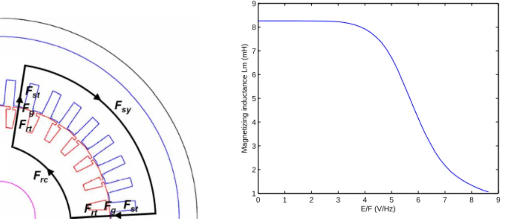
3.5 Left: mean flux line for saturation factor computation. Right: typical magnetising inductance
curve in function of air-gap flux. . . 29
LIST OF FIGURES
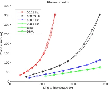
3.7 Experimental and simulated stator phase currents at several supply frequencies and supply
volt-ages (motor M2, s = 0.01%). . . 31
3.8 Experimental and simulated (Diva) phase current as a function of slip on M3 motor (U0=810 V,
fs= 150 Hz). The nominal slip is 1.56 %. . . 31
3.9 Rotor current distributions among bars obtained with FEM (left) and Diva (right) (motor M2,
fs= 150 Hz, s = 1%). . . 31
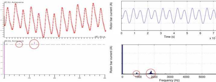
3.10 Rotor bar current waveforms obtained with FEM (left) and Diva (right) (motor M2, fs= 150 Hz,
s = 1%). FEM spectrum abscissa is graduated in multiples of the supply frequency (harmonics
6 and 12 stand for 6fsand 12fs frequencies), whereas Diva spectrum is directly graduated in Hz. 32
3.11 Experimental and simulated (Diva) stator phase current on M5 motor (asynchronous PWM with
fc= 1280 Hz, U0=30 V, fs=5 Hz, s=0.01 %). . . 32
3.12 Left: decomposition of a stator winding function (wf) in a sum of two turn functions (tf). Right: stator turn function of a single coil. . . 33
3.13 Motor M2 winding pattern, winding functions and resulting mmf in full-pitch case (left, Y /sps=6/6)
and shorted-pitch case (right, Y /sps=5/6). . . 33
3.14 Motor M1 winding pattern, winding functions and resulting stator mmf. . . 34
3.15 Stator mmf distribution along the air-gap at t=0 (motor M2 to M4, 5/6 shorted-pitch winding
cf. Fig. 3.13). The main space harmonics are here 11p = 33 and 13p = 39. . . 34
3.16 Left: rotor turn function. Right: rotor mmf distribution along the air-gap at t=0 (motor M2).
The main space harmonics are here Zr− p = 25 and Zr+ p = 31. . . 35
3.17 Csfunction marking the location of stator slot openings on motor M2. . . 36
3.18 Permeance per unit area distribution along the air-gap (motor M2, fs= 50 Hz) at t=0 (left) and
in function of time at αs=0 (right). . . 36
3.19 Saturated permeance per unit area distribution along the air-gap (motor M2, fs= 50 Hz) at t=0
(left) and in function of time at αs=0 (right). . . 37
3.20 Illustration of the air-gap radial flux density flattening due to even order saturation permeance waves. . . 37 3.21 Left: permeance per unit area distribution along the air-gap (motor M2, 5% static eccentricity,
fs= 50 Hz) at t=0. Right: permeance per unit area distribution in function of time (motor M2,
5% dynamic eccentricity, fs= 50 Hz) at αs=0. . . 38
3.22 Lef: radial air-gap flux density distribution along the air-gap at t=0 (motor M2). The main space
harmonics are here Zs− p = 33 and Zs+ p = 39. Right: Maxwell pressure, stator and rotor
magnetomotive forces, and permeance distributions at t=0 (motor M2). . . 39
3.23 FEM and Diva fundamental radial air-gap flux density as a function of phase voltage on M3
motor at fs= 150.2 Hz (left) and M2 motor at fs= 50.11 Hz (right) (no-load unsaturated case,
s = 10−4). . . . 39
3.24 FEM and Diva radial flux density distribution along the air-gap (left) and in function of time
(right) (motor M3, sinusoidal no-load case, s = 10−4, f
LIST OF FIGURES
3.25 Approximated FEM and Diva stator mmf (left) and permeance (right) distributions along the
air-gap (motor M2, fs= 50.11 Hz, U0= 173.2 V, s = 10−4). . . 40
3.26 Left: FEM and Diva main flux density saturation harmonic of spatial order 3p in function of the applied phase voltage on motor M2, after having fit the analytical model. Right: FEM and
Divaflux density distribution along the air-gap in saturated case. . . 41
3.27 Diva and FEM radial flux density distribution along the air-gap in sinusoidal on-load case (U0=
173.2 V, fs= 50 Hz, s = 1%). . . 41
3.28 Phase current, air-gap flux E0/fs, output torque, output power, efficiency, phase voltage and slip
in function of speed, obtained with ALSTOM simulation tool and Diva (motor M5a). Friction
losses have been experimentally determined and used both simulation tools. . . 44
3.29 Experimental and simulated (Diva) power factor, output torque and output power as a function
of slip on M3 motor (U0=810 V, fs= 150 Hz). . . 45
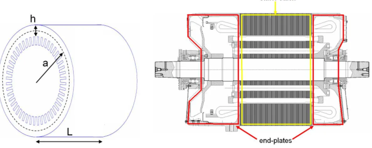
3.30 Left: stator stack equivalent cylinder dimensions. Right: motor M5 stator stack and end-plates. . 46
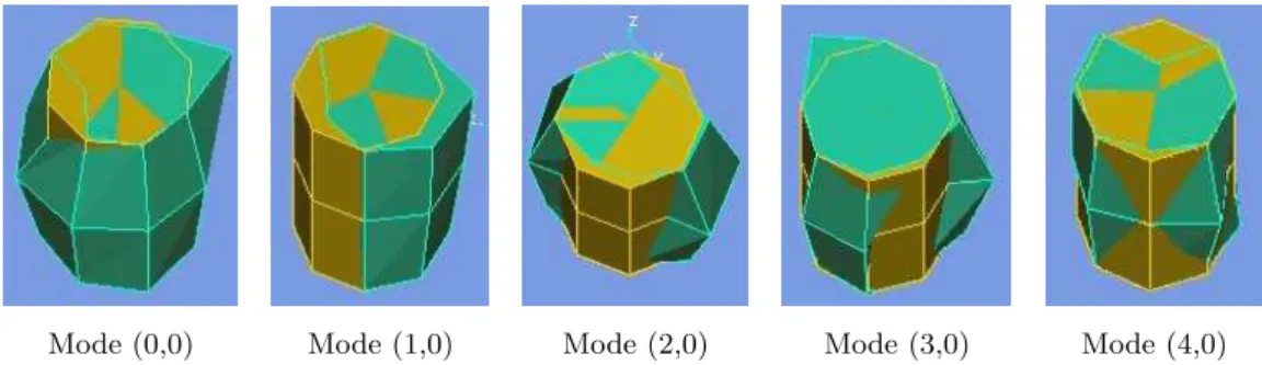
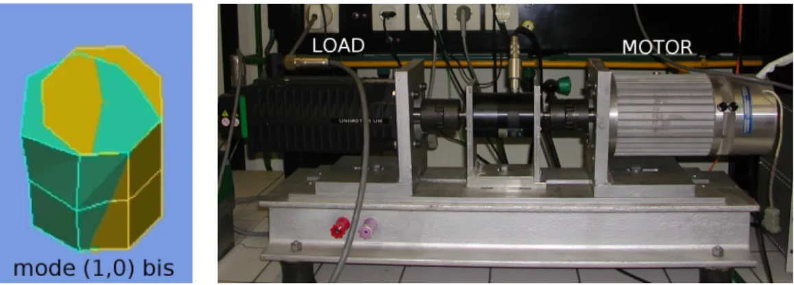
3.31 Deflection shapes of the first five stator circumferential modes (m = 0: breathing mode, m = 1: rotor bending mode, m = 2: elliptical mode, m = 3: 3-order elliptical mode, m = 4: 4-order elliptical mode. . . 49
3.32 Relative static displacement in function of Rsy/hsyratio for several modes. Doubling the relative
static displacement increases the SWL at resonance of 10 log10(22) ≈ 6 dB. . . 52
3.33 Experimental and simulated vibratory spectrum obtained (motor M1, s = 3 %, fs = 75 Hz,
U0= 6 V). . . 53
3.34 Experimental (left) and simulated (right) acceleration spectrogram in sinusoidal case (motor M1,
fs=12 to 60 Hz). An uncertainty exists on the experimental supply frequency as no tachometer
probe could be used. . . 53
3.35 Left: OMA deflection shape at 713 Hz (second bending mode, motor M1). Right: M1 motor
test-bench. . . 53
3.36 Measured (left) and simulated (right) acceleration spectrogram in on-load asynchronous PWM
case (motor M1, fc= 1600 Hz, fs= 10 to 80 Hz). . . 54
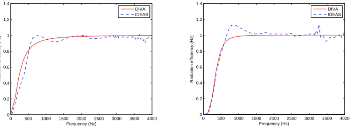
3.37 Diva and FEM radiation efficiency under an exciting force wave of order 0 (left) and order 1
(right) (magnitude 250 N/m2). . . . 55
3.38 Diva and FEM radiation efficiency under an exciting force wave of order 2 (left) and order 4
(right) (magnitude 250 N/m2). . . . 56
3.39 Diva and FEM+BEM sound power level generated by a rotating force wave of order 2 (left) and 4 (right). . . 57 3.40 Diva and FEM+BEM sound power level generated by a pulsating force wave of order 0, and a
combination of a order 2 and 3 rotating force waves. . . 57
3.41 Study of the vibration response of symmetrical or asymmetrical cylinder subjected to a rotating force wave of order 4. . . 58
LIST OF FIGURES
3.42 Experimental (left) and simulated (right) sonagram on motor M3 in sinusoidal no-load case. Note that experimental sonagram abscissa is time in seconds, as no tachometer prove was available,
whereas simulated sonagram abscissa is fsin Hz. . . 59
3.43 Experimental and simulated (Diva) A-weighted SWL spectrum in asynchronous PWM case
(mo-tor M5, fs=5 Hz, fc=1280 Hz). . . 60
3.44 Schematic view of motor M5/M5a stator stack and welded plated with rods (the slot number and
the slot shapes have been changed on purpose). . . 61
3.45 Experimental and simulated (Diva) stator phase current magnitude spectrum at low frequencies
(motor M5, I0= 200 A, fs=5 Hz, fc=1280 Hz). The experimental supply frequency was slightly
over-estimated, which explains why experimental and simulated current harmonics do not appear
at exactly the same place. . . 61
4.1 Illustration of different force waves types. The nodes of rotating waves travel along the air-gap,
whereas standing waves ones stay at the same place. . . 68
4.2 Simulated SWL of a standing or rotating force wave of spatial order 4 and magnitude 250 N/m2.
At resonance, there is exactly a 3dB difference. . . 69
4.3 Complex FFT of shorted-pitch motor M2 stator mmf in sinusoidal case (fs= 50 Hz). . . 71
4.4 Experimental and simulated (Diva) acceleration spectrogram in sinusoidal case (motor M1, fs=12
to 60 Hz). . . 75
4.5 Stator deflection of order 3 due to a slotting vibration (motor M1, sinusoidal case, fs= 50 Hz). . 75
4.6 Pure slotting force waves on motor M1, and their propagation direction (c.c. r.: counter-clockwise
rotation, c. r.: clockwise rotation). Grey deflection indicates a time anterior to black deflection. . 76
4.7 Experimental (left) and simulated (right) sonagram on motor M2 in sinusoidal no-load case. . . . 77
4.8 Order analysis of motor M5 in sinusoidal case. Saturation line of spatial order m = −2 and
frequency fs(Zr(1 − s)/p + 4) ≈ 46fR therefore appears at the order 46 abscissa. . . 78
4.9 Operational Deflection Shape of motor M5 near 600 Hz (fs≈ 30 Hz i.e. 900 rpm). An elliptical
deflection of the stator stack is observed. . . 78
4.10 Influence of rotor skewing on the sound pressure level in on-load sinusoidal case. . . 79
4.11 Operational Deflection Shape of motor M5 at 1138 Hz (maximal flux, PWM no-load case, fs≈ 50
Hz - test by VIBRATEC). . . 79
4.12 3D shape of the saturation force harmonic of equation (4.22) due to rotor skewing. . . 80
4.13 Operational deflection shape at 942 Hz at two successive instants (motor M5, fs ≈ 50 Hz,
sinusoidal case). . . 82 4.14 Left: stator mmf without the fundamental. Right: corresponding magnetic noise spectrum with
stator modes contribution (motor M3, fs= 100 Hz). . . 82
4.15 Experimental stator current harmonic groups magnitude in function of supply frequency (motor
M5, asynchronous PWM with triangular carrier, fc = 1280 Hz). . . 84
4.16 Complex FFT of shorted-pitch motor M2 stator mmf in asynchronous PWM case (fs= 50 Hz,
LIST OF FIGURES
4.17 Pure PWM vibration waves (motor M1, fc=4 kHz), and their propagation direction (c.c. r.:
counter-clockwise rotation, c. r.: clockwise rotation). . . 86
4.18 Measured spectrogram sweeping the switching frequency from 2.5 kHz to 10 kHz (motor M1, fs= 50 Hz). . . 87
4.19 2D FFT of motor M5 magnetic radial force for s ≈ 1% (left) and s = 0 (right) in on-load
asynchronous PWM case (fc= 1280 Hz, fs= 40 Hz). . . 88
4.20 Evolution of the pure PWM acoustic line of frequency 2fc= 2560 Hz when progressively
increas-ing the load at constant fundamental stator current. . . 88
4.21 Frequency shift of main slotting PWM lines of motor M1 during starting phase in PWM
asyn-chronous case (fc = 1600 Hz). . . 89
4.22 Experimental spectrogram measured on motor M1 from fs= 0 to 70 Hz in PWM asynchronous
case (fc= 1600 Hz). . . 90
4.23 Slotting PWM vibration waves (motor M1, fc=4 kHz), and their propagation direction (c.c. r.:
counter-clockwise rotation, c. r.: clockwise rotation). . . 91
4.24 Experimental spectrogram measured on motor M1 from fc = 1 to 6 kHz in PWM asynchronous
case (fs= 50 Hz). . . 91
4.25 Experimental spectrogram measured on motor M5 in asynchronous PWM no-load case (fc= 1280
Hz). . . 92
4.26 Rotor slot number noise database for Zs= 27, p = 2 (motor M1). . . 96
4.27 Rotor slot number noise database for Zs= 36, p = 2 (motor M1). . . 97
4.28 Sound power level (dB) measured on motors M2 (Zr= 28), M3 (Zr= 26), M4 (Zr= 44) which
share the same stator, but with different rotor slot numbers, rotor slot shapes, and air-gap widths. 97
4.29 Magnitude of main slotting forces in function of stator and rotor slot opening widths bs and br. . 98
4.30 Simulated sonagram of motor M6 in sinusoidal no-load case. . . 99
4.31 Rotor or stator slot opening smallest optimal value to cancel a slotting harmonic linked to integers krand ks. . . 101
4.32 A-weighted SWL spectrum at motor M7 mode number 4 resonance (fs= 44.2 Hz), for the initial
rotor slot opening value (left) and the optimal value (right). . . 102
4.33 SWL radiated by the slotting lines associated to ks0= 3 and kr0= 4 in function of the rotor slot
opening brvarying from 0 to τr(motor M7). The three non zero minima correspond to the three
br values of equation (4.48). . . 102
4.34 Simulated sound power level of motor M7 without current injection (no-load sinusoidal case, fs≈ 31 Hz). . . 106
4.35 Simulated sound power level of motor M7 with current injection, cancelling the slotting force of
frequency fs(4Zr(1 − s)/p + 2) and order 4 (left), and cancelling the slotting force of frequency
fs(4Zr(1 − s)/p − 2)) and order 4 (right). . . 106
4.36 Illustration of NSGA ranking method in case of two objectives f1 and f2. Individual j is
non-dominated by i if there exist k ∈ [1, N] such as fkj < fki, fki denoting the k-th objective function
LIST OF FIGURES
4.37 Final population (Pareto front) objectives 2-D projections (motor M6 optimisation). . . 113
4.38 Motor sections of different individuals. . . 114
4.39 Diva simulation of magnetic noise emitted by industrial motor M5a and prototype M7 during starting phase (no-load sinusoidal case). . . 114
4.40 Rotor of prototype M7. . . 115
4.41 Experimental set-up. . . 116
4.42 Sound pressure level of prototype M7, compared to the industrialised motor M5a, and its skewed rotor version M5 (sinusoidal no-load case). . . 117
4.43 Sound pressure level of prototype M7, compared to the industrialised motor M5a, and its skewed rotor version M5 (sinusoidal on-load case). . . 118
4.44 Sound pressure level spectrum of prototype M7 (asynchronous 1280 Hz PWM no-load case). . . . 118
4.45 Sound pressure level of prototype M7 during starting phase, using various switching frequencies (left: noise level in function of time, right: maximum and average noise levels from 10 to 50 Hz). The default asynchronous PWM switching frequency used on the industrialised motor M5a is 1280 Hz. . . 119
4.46 Illustration of the interference between main slotting lines (in black) and pure PWM lines (in blue), in asynchronous 1280 Hz PWM no-load case (left: fs= 35.43 Hz, middle: fs= 35.55 Hz, right: fs= 35.66 Hz). . . 120
A.1 FEM model of motor M7 (OPERA software). . . 128
B.1 Modal base of a cylindrical shell (I). . . 130
B.2 Modal base of a cylindrical shell (II). . . 131
Nomenclature
Roman Symbols
Bg Radial air-gap flux density
br Rotor slot opening width
bs Stator slot opening width
c0 Speed of sound in air
Df Stator frame diameter
df
r Rotor fictitious slot depth
df
s Stator fictitious slot depth
Dsh Rotor shaft diameter
Dri Rotor stack inner diameter
Dsi Stator stack inner diameter (bore diameter)
Dro Rotor stack outer diameter
Dso Stator stack outer diameter
Er Rotor stack Young modulus in radial direction
Es Stator stack Young modulus in radial direction
Esh Rotor shaft Young modulus in radial direction
fs
n PWM n-th time harmonic of stator phase current (f0s= 0, f1s= fs)
fR Rotor mechanical frequency (= 2πΩR)
fmax Maximum fundamental stator supply frequency
fs Fundamental stator supply frequency
g Air-gap width
LIST OF FIGURES
hf Stator frame width
hsy Stator yoke height
I0
1 Stator fundamental phase current
I0
2 Rotor branch fundamental current
ib
r Rotor b-th bar current
iq
s Stator q-th phase current
Kc Carter slotting coefficient
Ks Saturation coefficient
ks
w0 Stator winding fundamental distribution factor
L0
2 Rotor equivalent inductance (without skin effect)
Lf Stator frame length
Lr Rotor stack length
lrb Distance between rotor shaft bearings
Ls Stator stack length
lsh Rotor shaft length
M Number of objectives functions
ms Number of stator slots per pole and per phase
N Number of design variables
nl Stator winding layers number
Nb
r Winding function of b-th rotor bar
ns Number of turns in series per phase in stator winding
Nq
s Winding function of q-th stator phase
Nsp Number of angular discretisation steps per pole pair
Nti Number of time discretisation steps per electrical period
Ntrs Number of simulated rotor turns
p Number of pole pairs
Pf ri Friction power losses
Prt
LIST OF FIGURES
PIRry Rotor yoke iron power losses
Pr
IR Total rotor iron power losses
PIRsy Stator yoke iron power losses
Pst
IR Stator teeth iron power losses
Pr
J Rotor Joule power losses
Ps
J Stator Joule power losses
qr Number of stator phases
qs Number of stator phases
R0
2 Rotor equivalent resistance (without skin effect)
Rg Air-gap average radius (= Rsi− g/2 = Rro+ g/2)
Rro Rotor stack outer radius
Rsi Stator inner radius (= Dsi/2)
Rsy Stator yoke (back core) mean radius (= Rso− hsy/2)
s Fundamental slip
slr Rotor slotting ratio
sls Stator slotting ratio
smn Harmonic slip linked to stator current n-th time harmonic and mmf m-th space harmonic
sps Number of stator slots per pole (= Zs/2/p)
T Fr Rotor turn function
T Fs Stator turn function
Y Stator coil pitch
Zr Rotor teeth number
Zs Stator teeth number
Greek Symbols
αs Angular position in stator steady frame (rad)
βx Coefficients ±1 involved in flux density harmonics
δx Coefficients ±1 involved in radial force harmonics
LIST OF FIGURES
η Motor efficiency
ηx Coefficients ±1 involved in mmf harmonics
λde Dynamic eccentricity degree
λse Static eccentricity degree
λR Motor rotation direction (= ±1)
µs Stator stack Poisson ratio
νr Rotor mmf space harmonics
νs Stator mmf space harmonics
ΩR Rotor mechanical pulsation (= (1 − s)ωs/p)
ωr Rotor bar current fundamental pulsation (= (1 − s)ωs)
ωs Stator current fundamental pulsation (= 2πfs)
ρr Rotor stack mass per unit volume
ρs Stator stack mass per unit volume
σm Motor radiation efficiency of circumferential mode number m
τr Rotor slot pitch (= πDro/Zr)
τs Stator slot pitch (= πDsi/Zs)
ξm Damping coefficient of mode m
Acronyms
BEM Boundary Element Method
DIVA Name of the simulation software (DImensionnement VibroAcoustique
DTC Direct Torque Control
EMA Experimental Modal Analysis
emf Electromotive force
FEA Finite Element Analysis
FEM Finite Element Method
FFT Fast Fourier Transform
GA Genetic Algorithm
LIST OF FIGURES
NSGA Non-dominated Sorting Genetic Algorithm
ODS Operational deflection shapes
OMA Operational Modal Analysis
PFM Pulse Frequency Modulation
PWM Pulse-Width Modulation (regular sampling type) RFPM Random Frequency Pulse-Width Modulation RPPM Random Pulse-Position Modulation
RPWM Random Pulse-Width Modulation
RSF Random Switching Frequency
SEA Statistical Energy Analysis
SPEC Single Phase Equivalent Circuit
SPL Sound Pressure Level
SWL Sound Power Level
wf Winding function
Chapter 1
Introduction
1.1
Background
As the urgency of a global sustainable development policy grows in public consciousness, searching for a sus-tainable mobility - safe, efficient, eco-friendly and human-friendly - is one of the current greatest scientific challenge.
Among the existent means of transportation, the electric railway system has many advantages: its engine does not emit any greenhouse gas and runs with electricity, on the cleanest sources of energy today, assuming that cleanliness does not apply to the management of long-term nuclear wastes.
Furthermore, noise has become a major factor in qualifying our environment quality: one third of the
Europeans complains about noise (100). At same exposure level, the noise emitted by planes is more unpleasant
than the one emitted by cars, whereas noise due to railway traffic, which concerns between 2 and 4 % of the european population, is generally less annoying than the car traffic one. The estimated cost of railway noise (through its effects on health, the building of noise-reducing infrastructures, the depreciation of lands, etc.) is inferior to the ones of road and air traffics.
However, light-rail vehicles often drive close to residents, alike subways in the aerial parts of their track, and the demand of higher transport capacity tends to place passengers closer to the engine. The noise requirements of operators have therefore become stricter, and low noise traction motors are now a key success factor for railway industries.
1.1.1
Noise of railway transport systems
1.1.1.1 Sources of noise
The sources of noise in railway transport systems are traditionally classified in three types: • aerodynamic source (e.g. train turbulence and ventilation, motor fan)
• mechanical source (e.g. train wheel-rail squealing noise, motor bearings and gearbox)
• magnetic source (e.g. traction box transformers, inductances and rheostatic braking resistances, motor stator and cables)
1.1 Background
Audible noise always has an aerodynamic origin, in the sense that it is produced by air vibrations occurring in the audible range [20 Hz, 20 kHz]. The magnetic source of noise is defined as audible noise coming from vibrations due to magnetic forces, and therefore stops as soon as the machine is current-free. However, bearings noise comes from the shaft rotation, which comes itself from the action of electromagnetic torque: mechanical
noise could therefore be considered as a type of magnetic noise1. Such a classification has no physical
founda-tion, and was probably more guided by the different specialisations of engineers (aerodynamics, mechanics or electromagnetism).
The contribution of these three sources to the global sound power level, and the class of people exposed to noise, depend on the application (subway, light-rail vehicle, regional or high-speed train), on the traction motor topology (water-cooled or fan-cooled motor, self-ventilated or not, opened or closed enclosure) and type (synchronous permanent magnet motor, induction motor), and on speed. In starting phase, the aerodynamic source is generally low, and the current level is maximum in order to develop the maximum torque, leading to high magnitude magnetic forces. On the contrary, at high speed, the air-gap flux is lower, and aerodynamic noise generally covers magnetic noise. In both starting and braking phases, several PWM strategies are employed and significantly enrich the magnetic noise spectrum. The noise of high speed trains mainly affect residents, whereas the noise emitted by subways and light-rail vehicles can annoy both passengers (including the driver) and frontage residents, as traction and braking mainly occur in railway stations.
Magnetic noise generally occurs in traction machines at relatively high frequencies (500 Hz to 4 kHz, far from mechanical frequencies), and is often characterised by high tonalities: the total noise spectrum presents sharp peaks, creating an unpleasant sound which is penalised by acoustic norms. These tonalities are also characteristic of fan noise (siren effect).
1.1.1.2 Acoustic norms
The only current international acoustic norm on traction motors is the International Electrotechnical Commis-sion standard IEC 60034-9 (Rotating electrical machines - Part 9: Noise limits). It specifies a total sound power
level (SWL) limit in dBA2 depending on speed, as shown in Fig. 1.1.
Figure 1.1: IEC 60034-9 norm noise limit
1Magnetic noise is also sometimes called electrical noise, but the term of electromagnetic noise is reserved to the electromagnetic
compatibility (EMC) field.
1.2 Objectives
This norm also defines how to penalise the pure tones occurring in the one-third octave band spectrum (Fig. 1.2).
Figure 1.2: IEC 60034-9 norm tonalities penalisation. ∆L is the average of the sound levels of the adjacent one-third octaves: the correction in dB must be added to the global sound power level in dBA.
The noise level must be measured at no-load and under sinusoidal supply. These normalised test conditions
are highly questionable, as it has been already pointed out by some authors (109), notably because pulse-width
modulation (PWM) supply significantly changes the motor noise (see section 2.2.1.3): some operators have
already reported some complaints coming from residents or passengers, even when the IEC norm was fulfilled. The prediction of the audible magnetic noise due to PWM is therefore especially important when designing a traction motor.
1.1.2
PROSODIE Project
This thesis work is a part of a larger project, called PROSODIE (”PROpulsion Silencieuse Optimis´ee et Di-mensionn´ee pour l’Environnement”), which aims at understanding and predicting the audible magnetic noise emitted by inverter-fed traction motors, and by passive components such as inductors and transformers. Our work dealing with traction motors, which started in December 2005 and ended in September 2008, followed two main thesis works : Vibro-acoustic dimensioning and sensitivity analysis of alternative current
variable-speed machines (3), and Contribution to the study of acoustic noise generated by the association of an electrical
machine and its static power converter - application to the induction machine (83).
Besides the company ALSTOM-Transport and the laboratories L2EP and LEC, another important actor of the PROSODIE project is the company VIBRATEC, specialised in acoustic, vibration measurements and numerical simulation. They have performed three of the four test campaigns run on ALSTOM motors (three more campaigns have been carried on our own in LEC laboratory), and performed several simulations with the mechanical finite element method (FEM) software Ideas, and the acoustic boundary element method (BEM) software Sysnoise.
1.2
Objectives
The main objective of this work is to build some models able to predict the audible magnetic SWL emitted by a squirrel-cage induction machine in function of the motor design variables (slot numbers, dimensions, ...) and its PWM strategy parameters (switching frequency, type of PWM strategy, ...). These models must also be
1.3 General approach
able to compute the motor performances (output torque, efficiency) in order to help designing low-noise motors achieving some specified traction characteristics.
The simulation tool must be especially fast: firstly, it is necessary to calculate noise at variable speed (traction and breaking phases) in order to take into account resonance effects ; secondly, as induction motor design involves several conflicting objectives, the programme will be coupled to a multi-objective optimisation tool: if this task has to be handled by a 2 GHz laptop, the evaluation of one motor design must not last more than a few minutes. Therefore, the use of analytical models are favoured in this thesis, and FEM are only used as numerical validations besides experiments.
An underlying objective of this work is to break the limits of Ait-Hammouda and Hubert works (3;83),
comprising:
1. unsaturated hypothesis (linearity of voltage/current curve, and no saturation of the air-gap flux density shape) for both works
2. sinusoidal hypothesis (no inverter model) for Ait-Hammouda work
3. off-load hypothesis (zero slip, no rotor currents, no output torque computation) for Ait-Hammouda work 4. uncoupled mechanical structure and magnetic excitation for Hubert work
5. prohibitive computing time (up to 10 mn per motor speed) for both works
The first simulation tool programmed by Ait-Hammouda (referred as Diva1 1.0, opposed to Diva 2.0
which was developed during our work) also suffered from several computing limitations (shorted-pitch was not correctly taken into account, and fractional-slot modelling was not possible), and a lack of visualisation tools. Other problems came from the fact that all the electromagnetic air-gap distributions (windings and permeance) were calculated as Fourier series in the programme, giving low-accuracy and time-consuming results. This old version has therefore been completely reworked, and nothing remains of it in Diva 2.0.
1.3
General approach
In a first part, a general overview of previous works is done (chapter 2). The different electromagnetic and
vibro-acoustic models found in literature are presented, and the analytical models adopted in this thesis, as well as their underlying assumptions, are argued. The noise reduction methods seen during the bibliographic study are then detailed: they include low-noise design rules, based on the influence on magnetic noise of motor design variables, environment and supply current, and active methods such as current injection. Finally, the works dealing with induction machine optimal design are considered, especially when they include the vibro-acoustic factor.
In a second part, the analytical models chosen along the first part are exposed in depth (chapter3), and at
its stage of the computations, some simulation results with Diva (2.0 will be omitted in the rest of the thesis)
1.3 General approach
are presented and validated. The air-gap radial flux density computation is first presented and validated includ-ing load, PWM and saturation effects. The mechanical and acoustic analytical models are also presented and validated by FEM and/or tests on induction machines from 0.7 to 350 kW. Along this part, some experimental validations will be made on different motors, noted from M1 to M7, whose main characteristics are given in
AppendixA.2(note that M2, M3 and M4 share the same stator, as well as M5 and M7). Indeed, ALSTOM
test-benches were not enough available and flexible to ensure all the test campaigns, and they required a high safety level which did permit all needed measurements. Moreover, ALSTOM experimental data was not necessarily gathered on the same motor. Validations have thus been carried on two main types of motors: the small power motor of LEC laboratory (M1), on which any PWM strategy could be implemented and any measurement could be carried, and the medium power motors of ALSTOM Transport (M2 to M6). More than a lack of coherence, this should be seen as the opportunity to validate the model implemented in this thesis on a very wide power range. Note that when ALSTOM motors are concerned, some data (drawings, noise levels) have been modified for confidentiality reasons.
In a third part, new methods to reduce magnetic noise annoyance at the design stage are investigated (chapter
4). The most important magnetic force waves are first analytically characterised in terms of frequency, number
of nodes and propagation direction, and experimentally validated. On the ground of these analytical results, some noise reduction guidelines are established acting on the motor geometry (slot numbers, slot openings) and PWM strategy. Finally, a constrained multi-objective optimisation technique is presented and applied to an industrialised traction machine. To ensure the validity of these approaches, two low-noise motor prototypes for a subway application are designed. One of them is manufactured and successfully tested: it improves the noise level on the whole speed range, and noise reduction reaches 15 dBA in off-load sinusoidal case. Some changes are also proposed on the PWM strategy, and a 5 dBA noise reduction is obtained.
In a last part (chapter 5.1), the conclusions of this thesis work are drawn. Some weaknesses of Diva
analytical models are then pointed out for future work, and some new research fields that could be investigated using Diva are finally proposed.
More resources about this thesis work can be found on the internet at the following address: http://l2ep.univ-lille1.fr/pagesperso/lebesnerais/
Chapter 2
State of the art and orientation of the
work
In this chapter, an overview of the most important works seen during the bibliographic study are presented. As the thesis scope involves several fields of physics (electromagnetism, mechanics, acoustics) and mathematics (optimisation), an exhaustive list of all the references studied during these three years would be inappropriate: the more distinctive publications have been selected in terms of clearness, scientific rigour, synoptic view and pioneering work.
Modelling magnetic noise generation requires to model both the electromagnetic exciting force and the mechanical response of the excited structure (magnetic force / structure vibration transfer). Once the vibrations of this structure are known, an acoustic model is necessary to compute the sound power level radiated by the machine (air vibrations / SWL transfer). This first part details the different analytical models that were found
in literature. The most appropriate ones to fulfil our goals (cf. section1.2) are chosen, and all their assumptions
are clarified.
2.1
Electromagnetic and vibro-acoustic modelling
2.1.1
Electromagnetic forces modelling
Magnetic forces occurring in electrical machines are traditionally classified in three types: 1. Maxwell forces (sometimes called reluctance forces)
2. Laplace forces
3. magnetostrictive forces
This classification, which is often reported in literature, is as ill-defined as the previous one on noise sources:
indeed, as pointed out in (15), one must distinguish force distributions or densities, acting on differential
vol-umes or surfaces of the machine, from total forces, which are integrals of force distributions on some parts of the machine (e.g. conductors for Laplace forces). Moreover, Maxwell forces are often expressed from the definition of the Maxwell tensor, whose general definition already contains the Lorentz force.
2.1 Electromagnetic and vibro-acoustic modelling
Neglecting the electrical fields, the i-th component of the force density applying on a given volume element
of the motor can be written under the form (136) :
fi= [div(Y)]i+ [j × B]i− 1 2 3 X j,k=1 HjHk∂iµjk− 1
2[rot(H × B)]i+ [div(Φ)]i+ [div(Ψ)]i (2.1)
where fi stands for the i-th (i=1,2,3 being the Cartesian coordinates in basis (x1, x2, x3)) component of
force vector f, and µjk is the magnetic permeability second order tensor (matrix) assuming the medium is
anisotropic. The meaning of these six components is the following:
1. Y = C(E) is the mechanical stress tensor, C is the elasticity tensor and E the strain tensor. In the linear case we have yij=P3k,l=1cijklǫkl (Hooke’s law).
2. j × B is the Lorentz force per unit volume which applies to a coil flowed by a current j in an external flux density field B (also called Laplace force in its integral form).
3. −1
2HjHk∂iµjk describes the force per unit volume caused by magnetic permeability inhomogeneities,
assuming that it does not depend of the magnetic field intensity. 4. −1
2[rot(H × B)]i represents a torque (136) which vanishes if H and B are colinear.
5. Φ is the magnetostriction tensor, related to the strain dependence of the magnetic permeability. 6. Ψ is the thermal stress tensor.
Using the conservation of magnetic flux, the magnetic force densities number 2, 3 and 4 can be expressed
by a magnetic tensor called Maxwell tensor (96):
Tij = 1 2(HiBj+ HjBi− 3 X k=1 δijHkBk) (2.2)
The extra-diagonal terms of this tensor stand for magnetic shear stresses, whereas the diagonal terms stand for magnetic normal stresses. All the magnetic stress present in an electrical machine parts, which vanishes when it is magnetic-field free (i.e. current-free in induction motors), either comes from Maxwell stress or magnetostrictive stress.
Focusing of these magnetic forces, the electromagnetic force density can be be written as
f = div(T + Φ) (2.3)
2.1.1.1 Maxwell forces
Assuming that B = µH (isotropic permeability), and taking a surface dS with normal direction x3(Fig. 2.1),
the magnetic stresses in its normal and tangential direction are given by
σt= T23= µHnHt σn= T33=
1
2µ(H
2
2.1 Electromagnetic and vibro-acoustic modelling
Figure 2.1: Left: definition of dS surface and its normal and tangential directions. Right: definition of the local
coordinate system defined by a magnetic field line (from (14)).
In an induction machine, where cylindrical coordinates (r, θ, z) are more adapted, σn becomes σr and σt
becomes σθ. The modulus of this stress is constant and independent of the surface orientation. It is given by
q σ2 t+ σ2n= µ 2|H| 2 (2.5)
which is the electromagnetic energy density (homogeneous to a pressure, which explains the use of the expression ”Maxwell pressure”) at that point. A geometrical interpretation of that magnetic stress is also
reported in (14): the angle ∆ between the magnetic force which applies to a given surface and its normal
direction is twice the one between the local magnetic field line direction and the surface normal direction. As a consequence, when H is perpendicular to a surface (∆ = 0), the magnetic force seen by that surface is collinear to H; when H is parallel to a surface (∆ = π/2), the magnetic force is also perpendicular to the surface, but in
opposite direction (see Fig. 2.2).
Figure 2.2: Direction of total Maxwell stress for different magnetic line directions.
If Maxwell tensor is expressed in the local coordinates defined by a given magnetic field line (cf. Fig. 2.1),
it becomes T = µ − 1 2|H| 2 0 0 0 −12|H| 2 0 0 0 12|H|2 (2.6)
Two different stresses therefore occur in the perpendicular plane of the magnetic line, and in the direction of the magnetic line: the first one can be interpreted as an hydrostatic magnetic pressure, which tends to keep the magnetic field lines away from one another; the second one can be interpreted as a magnetic tension which
2.1 Electromagnetic and vibro-acoustic modelling
which ”inflates” a deformable solenoid, while the second one corresponds to the law of minimal reluctance, which tenses the solenoid.
Expression (2.4) can also be found using the Ostrogradsky theorem (or divergence theorem) (15), which
shows that the volume integral of the Maxwell stress divergence can be reduced to a surface integral enclosing the volume under consideration:
F = Z V f dτ = Z S/V⊂S T.dS (2.7)
If we want to calculate the total Maxwell force which applies on the volume V of the full stator, we can define a closed surface S composed of a cylinder in the air-gap, another cylinder outside the motor, and two rings in the motor end-regions. Assuming that the magnetic field vanishes outside the machine, the surface integration integration over S is reduced to a surface integration over the air-gap cylinder:
Fstator= Z 2π θ=0 Z Ls z=0 T.urrdθdz = Z 2π θ=0 Z Ls z=0 (µ0HrHθur+ 1 2µ0(H 2 r− Hθ2)uθ)rdθdz (2.8)
The Maxwell stress at the interface between the air-gap and the stator stack can therefore be expressed as
σn = 1 2µi(H 2 n− Ht2) − 1 2µ0(H ′2 n− H ′2 t) (2.9) σt = µiHnHt− µ0H′nH′t (2.10)
where µistands for the magnetic permeability of iron, H stands for magnetic field values in the iron, whereas
H′ stand for magnetic field value in the air. Using the continuity laws of flux density and magnetic field, we
have Ht= H′tand Bn= B′n, so that
σn = H′2 t 2 (µ0− µi) + B′2 n 2 ( 1 µi − 1 µ0 ) =1 2(µ0µiH ′2 + B′2 n)( 1 µi − 1 µ0 ) (2.11) σt = 0 (2.12)
Maxwell stress at the interface between air-gap and stator iron (in front of stator teeth) is therefore a normal stress, in radial direction. Note that at this stage of the analysis, no assumption has been made on the fact that magnetic flux density lines radially enter in stator teeth. The property of a purely radial Maxwell stress at the interface is independent of the incidence angle of the flux density lines, and only comes from continuity laws.
This radial stress tends to pull stator towards rotor (law of minimal reluctance), it is a negative pressure
which applies on the inner surface of the stator. As illustrated in Fig. 2.3, only a small amount of flux density
lines enters in teeth sides. If the inner surface of stator slots had been included in the surface integration, we would have found some additional Maxwell forces acting on stator teeth sides in transverse direction. These
tangential forces can play an important vibro-acoustic role in certain cases, e.g. in large turbines (66;68; 127)
where the teeth bending natural frequencies can be excited (their natural frequency computation is detailed for
instance in (63)). In (137), some tangential tooth forces linked to PWM supply are also shown to be superior or
2.1 Electromagnetic and vibro-acoustic modelling
stator yoke and frame, and efficiently radiated in audible sound power level, whereas their bending is damped by windings and wedges, and badly transmitted to the stator frame: these tangential Maxwell forces will be neglected in this work.
Figure 2.3: Example of flux density lines distribution in an induction machine, in unsaturated case: the main part of the magnetic flux enters perpendicularly to tooth tips.
As µ0≪ µi, the radial Maxwell stress can finally be approximated by
σn≈ − 1 2µ0 (µ0µiH′2t+ B ′2 n) = − 1 2µ0 (µi µ0 B′2 t+ B ′2 n) (2.13)
In non-saturated case, magnetic flux lines enter almost perpendicularly into the iron (cf. Fig. 2.3), so that
µiB′t≪ µ0B′n, and a new approximation of σn can be made:
σn≈ −
B′2 n
2µ0
(2.14) This negative radial pressure is here assumed to be the only significant source of audible magnetic noise in
traction machines. In order to compute it analytically, the expression of the radial flux density B′
n at the outer
surface of stator teeth is needed. As the air-gap is generally very thin, B′
n is approximated by the flux density
value in the middle of the air-gap.
Expression (2.14) is only valid considering that stator iron has a linear characteristic. The effect of
satura-tion will therefore have to be treated separately (see secsatura-tion2.1.1.3.2).
Laplace forces are the integral expression of Maxwell forces on conductors, i.e. stator windings and rotor bars in an induction machine. They can produce high vibrations of the stator end-windings in both starting
transient and steady state conditions (115). However, the stator slots flux density is too low to produce
significant vibrations of the yoke, and stator conductors are wedged into slots. Acoustic noise due to Laplace forces is therefore neglected in this work.
2.1 Electromagnetic and vibro-acoustic modelling
2.1.1.2 Magnetostriction forces
The general phenomenon of magnetostriction in active materials comprise an isotropic phenomenon called
volume magnetostriction, and an anisotropic phenomenon called Joule and transverse magnetostriction (15).
Volume magnetostriction occurs in the iron at magnetic fields superior to 8 kA/m, but it can be neglected in the two-dimensional iron sheets of the stator stack: magnetostriction will therefore only refer to Joule and transverse magnetostriction in the following.
Magnetostriction is a magnetomagnetic phenomenon which stretches or shrinks a material in the magnetic
field lines direction (Fig. 2.4), keeping its volume constant (15;69). The elongation value for an electrical iron
sheet can reach from 1 to 10 µm/m, which is also the order of magnitude of Maxwell relative displacements1.
Figure 2.4: Simplified representation of a material flux density lines (left) and the resulting magnetostrictive effect (right).
Magnetostrictive forces are defined as the force field which creates the same strain than the magnetostrictive stress. This stress is partly due to the overlapping of the dipoles electronic clouds that compose the iron ferromagnetic material, when they naturally align with an external magnetic field. Another part of this stress
is produced at a larger scale between different domains of the crystalline structure (11;99). As Maxwell forces,
magnetostrictive forces depend on the observation direction and are therefore properly represented by a tensor.
Magnetostrictive vibrations occur at same frequencies than Maxwell vibrations (99): it is therefore impossible
to distinguish them on a vibration spectrum. Moreover, it is hard to quantify how much Maxwell efforts are greater than magnetostrictive efforts. It was shown in particular that in can depend on the deflection shape
of the stator (99): magnetostrictive deflections can either limit or reinforce Maxwell deflections at a given
frequency. An example of Maxwell and magnetostrictive force distributions is displayed in Fig. 2.5.
The relative importance of magnetostrictive and Maxwell forces strongly depends on the air-gap width, on the intrinsic magnetic properties of the iron (for instance, silicium-enriched materials limit magnetostriction
(92)), and on the frequency range. Many studies were carried on different motors with different assumptions,
leading to different conclusions.
As an example, a first study was made by Belmans (19) who suggested that magnetostriction was negligible.
Then, Garvey (67) proposed a method to compute magnetostriction effects, and its numerical application on a
large machine showed that magnetostriction was negligible. Some other works (94) on a 2.2 kW motor showed
that 10 to 30% of the magnitude of magnetic vibration lines were due to magnetostriction. The thesis work of
Laftman(99) conluded that magnetostrictive forces magnitude could be as high as Maxwell forces magnitude
1Taking the magnitude B2
0/(2µ0) of the fundamental Maxwell force, which has a 2p spatial order and 2fsfrequency, gives for
B0= 1.5 T on motor M5 an elongation of Y2pωs ≈310−6(see equation (3.39)). Note that kind of comparison can be misleading as
magnetic noise does not come from the low frequency fundamental magnetic vibration, but from some of its harmonics of higher frequencies and smaller magnitude (the same remark applies to magnetostrictive and Laplace forces).