HAL Id: tel-01091407
https://tel.archives-ouvertes.fr/tel-01091407v2
Submitted on 23 Oct 2018
HAL is a multi-disciplinary open access archive for the deposit and dissemination of sci-entific research documents, whether they are pub-lished or not. The documents may come from teaching and research institutions in France or abroad, or from public or private research centers.
L’archive ouverte pluridisciplinaire HAL, est destinée au dépôt et à la diffusion de documents scientifiques de niveau recherche, publiés ou non, émanant des établissements d’enseignement et de recherche français ou étrangers, des laboratoires publics ou privés.
Modeling and power control of a marine current turbine
system with energy storage devices
Zhibin Zhou
To cite this version:
Zhibin Zhou. Modeling and power control of a marine current turbine system with energy storage devices. Other. Université de Bretagne occidentale - Brest, 2014. English. �NNT : 2014BRES0094�. �tel-01091407v2�
THÈSE / UNIVERSITÉ DE BRETAGNE OCCIDENTALE
sous le sceau de l’Université européenne de Bretagne
pour obtenir le titre de
DOCTEUR DE L’UNIVERSITÉ DE BRETAGNE OCCIDENTALE
Mention : Science pour l'Ingénieur
École Doctorale EDSM
présentée par
Zhibin ZHOU
Préparée au sein de l'EA 3634 IRENav et de l'EA 4325 LBMS
Modeling and power control
of a marine current turbine
system with energy storage
devices
This Project has received financial support from Brest Métropole Océane
Thèse soutenue le 17 octobre 2014
devant le jury composé de :
Maria DAVID
Professeur, Institut National Polytechnique de Toulouse / rapporteur
Seddik BACHA
Professeur, Université Joseph Fourier, Grenoble / rapporteur
Seifeddine BENELGHALI
Maître de Conférences, Aix-Marseille Université / examinateur
Mohamed MACHMOUM
Professeur, Polytech'Nantes, Saint-Nazaire / président
Tianhao TANG
Professeur, Shanghai Maritime University, Shanghai / examinateur
Mohamed BENBOUZID
Professeur, Université de Bretagne Occidentale / directeur de thèse
Jean Frédéric CHARPENTIER
Acknowledgments
This work has been carried out at French Naval Academy Research Institute (EA 3436 IRENav) and at the Laboratoire Brestois de Mécanique et des Systèmes (EA 4325 LBMS) of the University of Brest. The financial support provided by Brest Métropole Océane (BMO) is gratefully acknowledged.
I wish to express my gratitude to my main supervisor Prof. Mohamed BENBOUZID for the consistently inspiration, encouragement and guidance throughout this work. I also wish to thank my supervisors Dr. Jean Frédéric CHARPENTIER and Dr. Franck SCUILLER for their valuable comments, suggestions and discussions related to this thesis and the published papers.
I wish to thank the pre-examiners Prof. Maria PIETRZAK-DAVID from National Polytechnic Institute of Toulouse and Prof. Seddik BACHA from the Polytechnic Institute of Grenoble for their valuable comments and corrections. I am also grateful to my PhD thesis defense committee members: Prof. Mohamed MACHMOUM from Polytech’Nantes, Dr. Seifeddine BENELGHALI from the University of Aix-Marseille and Prof. Tianhao TANG from Shanghai Maritime University, China.
Special thanks are due to Prof. Tianhao TANG for his suggestions in this PhD work as well as for encouraging me to apply for this research position in 2011.
I also wish to thank my friends Elhoussin, Dieudonné, Imad, Ousmane, Jingang HAN, Yang YI, Jing WU, Clément, Emerry, Dhafar, Sébastien, Ali, Farid, Sofiane, Omar; the friendship and the helps given by them have been very important to me.
Finally, I am deeply indebted to my parents, Xiujing BAI and Laibao ZHOU, for their infinite love and untiring support since the beginning of my life.
List of Publications
Main results of this PhD thesis have lead to the following publications.
I
NTERNATIONALJ
OURNALP
APERS[1] Z. Zhou, F. Scuiller, J.F. Charpentier, M.E.H. Benbouzid and T. Tang, “Power control of a non-pitchable PMSG-based marine current turbine at over-rated current speed with flux-weakening strategy,” IEEE Journal of Oceanic Engineering, pp. 1-10, 2014. (early access in IEEE Xplore)
[2] Z. Zhou, F. Scuiller, J.F. Charpentier, M.E.H. Benbouzid and T. Tang, “Power smoothing control in a grid-connected marine current turbine system for compensating swell effect,” IEEE Transactions on Sustainable Energy, vol. 4, n°3, pp. 816-826, July 2013.
[3] Z. Zhou, M.E.H. Benbouzid, J.F. Charpentier, F. Scuiller and T. Tang, “A review of energy storage technologies for marine current energy systems,” Renewable and
Sustainable Energy Reviews, vol. 18, pp. 390-400, February 2013.
I
NTERNATIONALC
ONFERENCEP
APERS[1] Z. Zhou, F. Scuiller, J.F. Charpentier, M.E.H. Benbouzid and T. Tang, “An up-to-date review of large marine current turbine technologies,” in Proceedings of the 2014 IEEE
PEAC, Shanghai (China), pp. 1-5, November 2014.
[2] Z. Zhou, F. Scuiller, J.F. Charpentier, M.E.H. Benbouzid and T. Tang, “Application of flow battery in marine current turbine system for daily power management,” in
Proceedings of the 2014 IEEE ICGE, Sfax (Tunisia), pp. 8-13, March 2014.
[3] Z. Zhou, F. Scuiller, J.F. Charpentier, M.E.H. Benbouzid and T. Tang, “Power limitation control for a PMSG-based marine current turbine at high tidal speed and strong sea state,”
in Proceedings of the 2013 IEEE IEMDC, Chicago (USA), pp. 75-80, May 2013.
[4] Z. Zhou, F. Scuiller, J.F. Charpentier, M.E.H. Benbouzid and T. Tang, “Grid-connected marine current generation system power smoothing control using supercapacitors,” in
Proceedings of the 2012 IEEE IECON, Montreal (Canada), pp. 4035-4040, October 2012.
- iv -
[5] Z. Zhou, M.E.H. Benbouzid, J.F. Charpentier, F. Scuiller and T. Tang, “Energy storage technologies for smoothing power fluctuations in marine current turbines,” in
Proceedings of the 2012 IEEE ISIE, Hangzhou (China), pp. 1425-1430, May 2012.
N
ATIONALC
ONFERENCEP
APERS[1] Z. Zhou, F. Scuiller, J.F. Charpentier et M.E.H. Benbouzid, “Intégration d’une batterie à circulation pour lisser la puissance quotidienne fournie par une hydrolienne sur un réseau îloté,” dans les Actes de Congrès SGE’14 (Symposium de Genie Electrique), Cachan (France), Juillet 2014.
[2] Z. Zhou, F. Scuiller, J.F. Charpentier et M.E.H. Benbouzid, “Lissage supercapacitif de la puissance produite par une hydrolienne connectée au réseau,” dans les Actes de Congrès
SHF- Energies Marines Renouvelables 2013, Brest (France), Octobre 2013.
[3] Z. Zhou, “Power smoothing and limitation control of a PMSG-based marine current turbine under swell waves,” dans les Actes de JCGE’13 (Journée des Jeunes Chercheurs
en Génie Electrique), Saint-Nazaire (France), Juin 2013.
Earth is a gift for all life; My life is a gift from my parents; Love and thankfulness to our parents and the Earth.
CONTENTS
INTRODUCTION ………....……1
CHAPTER I: State of the Art Survey of Energy Storage Technologies for Marine Current Turbines ……….3
I.1 INTRODUCTION... 4
I.2 TIDAL CURRENT TURBINE BACKGROUND ... 4
I.3 POWER FLUCTUATION PHENOMENA ... 10
I.4 BATTERY STORAGE TECHNOLOGIES ... 12
4.1LEAD-ACID BATTERIES ... 13
4.2NICKEL-BASED BATTERIES ... 13
4.3LITHIUM-ION BATTERIES ... 14
4.4SODIUM-SULPHUR BATTERIES ... 15
4.5FLOW BATTERIES ... 16
4.6BATTERY TECHNOLOGIES COMPARISON ... 17
I.5 FLYWHEEL TECHNOLOGIES ... 19
I.6 SUPERCAPACITOR TECHNOLOGIES ... 21
I.7 PHS AND CAES TECHNOLOGIES ... 23
7.1PUMPED HYDRO STORAGE ... 23
7.2COMPRESSED AIR ENERGY STORAGE ... 25
I.8 COMPARISIONS OF ENERGY STORAGE TECHNOLOGIES ... 26
I.9 CONCLUSION ... 29
CHAPTER II: Power Smoothing Control with Supercapacitors for Compensating Swell Effect on a Grid-Connected MCT System ……….………..………30
II.1 INTRODUCTION ... 33
II.2 SWELL EFFECT MODELING ... 33
- viii -
II.3 MODELS FOR A GRID-CONNECTED MCT SYSTEM ... 39
3.1MARINE CURRENT TURBINE MODEL ... 39
3.2MARINE CURRENT GENERATOR MODEL... 41
3.3POWER CONVERTER AVERAGE-VALUE MODEL ... 42
II.4 GENERATOR–SIDE POWER SMOOTHING CONTROL ... 43
4.1PICONTROLLERS TUNING ... 44
4.2PROPOSED MPPT FOR REDUCING POWER FLUCTUATION ... 47
4.3COMPARISON OF THE PROPOSED MPPT WITH TORQUE-BASED MPPT ... 52
II.5 GRID-SIDE POWER SMOOTHING CONTROL... 54
5.1GRID-SIDE CONVERTER CONTROL ... 54
5.2SUPERCAPACITOR ESS FOR GRID POWER SMOOTHING ... 55
II.6 COST AND LAYOUT ISSUES OF THE SC ESS ... 64
II.7 CONCLUSION ... 65
CHAPTER III: Daily Power Management with Flow Battery ESS………...66
III.1 INTRODUCTION ... 68
III.2 MCT-BASED HYBRID SYSTEM ... 68
III.3 FLOW BATTERY MODELING ... 70
3.1BATTERY EQUIVALENT CIRCUIT MODEL ... 70
3.2BATTERY PARAMETER CALCULATION PROCESS ... 71
3.3BATTERY SIZE AND BASIC CHARGE-DISCHARGE CHARACTERISTIC ... 74
III.4 HYBRID SYSTEM DAILY POWER MANAGEMENT ... 76
4.1SYSTEM CONFIGURATION AND BESSCONTROL SCHEME ... 76
4.2SIMULATION WITHOUT THE DG... 78
4.3SIMULATION WITH THE DG ... 81
4.4SIMULATION WITH A SMALLER DG ... 82
III.5 ISLAND POWER MANAGEMENT CASE ... 84
5.1ISLAND LOAD ESTIMATION ... 84
5.2POWER MANAGEMENT FOR THE ISLAND CASE ... 85
5.3CONCLUSION OF THE ISLAND CASE ... 93
III.6 CONCLUSION ... 94
CHAPTER IV: Control of the Non-Pitchable PMSG-Based Marine Current Turbine at Over-rated Current Speed ………...95
IV.1 INTRODUCTION ... 98
IV.2 GENERATOR OPERATING CHARACTERISTICS…... ….99
2.1OVER-RATED SPEED OPERATION ... 99
2.2STEADY-STATE ANALYSIS ... 100
IV.3 ROBUST FLUX-WEAKENING CONTROL ... 105
3.1THE SYSTEM CONTROL SCHEME ... 105
3.2SPEED CONTROL AND TORQUE CONTROL ... 106
3.3COMPARISON OF THE CAPMODE AND THE MAPMODE ... 112
IV.4 DISCUSSIONS ON GENERATOR PARAMETERS ... 119
IV.6 CONCLUSION ... 122
CONCLUSIONS & PERSPECTIVES………....…124
FRENCH ABSTRACT ………126
I. INTRODUCTION... 127
II. ETAT DE L’ART SUR LES SYSTEMES DE STOCKAGES D’ENERGIES POUVANT ETRE ASSOCIES AUX HYDROLIENNES... 128
II.1PROBLEMATIQUE DE L’HYDROLIEN ... 128
II.2 ETAT DE L’ART SUR LES SYSTEMES DE STOCKAGES D'ENERGIES ... 130
II.3 COMPARAISONS ET CONCLUSIONS SUR LES SYSTEMES DE STOCKAGE D'ENERGIE ... 132
III. LISSAGE DE LA PUISSANCE AVEC DES SUPER-CONDENSATEURS... 132
III.1MODELISATION DE LA HOULE ... 133
III.2LISSAGE DE PUISSANCE PAR ACTION SUR LA GENERATRICE ... 134
III.3LISSAGE DE LA PUISSANCE INJECTEE COTE RESEAU ... 135
III.4DISCUSSION ... 136
IV. INTEGRATION D’UNE FLOW BATTERIE POUR LA GESTION QUOTIDIENNE DE LA PUISSANCE ... 137
IV.1MODELISATION DE LA BATTERIE ... 137
- x -
IV.2SYSTÈME HYBRIDE HYDROLIEN/BATTERIE/DIESEL ... 138
IV.3CAS D’UNE ALIMENTATION INSULAIRE ISOLEE ... 139
V. STRATEGIE DE LIMITATION DE PUISSANCE AUX VITESSES DE COURANTS MARINS ELEVEES ... 141
V.1CARACTERISTIQUES DE FONCTIONNEMENT DE LA GENERATRICE ... 141
V.2CONTROLE ROBUSTE PAR DEFLUXAGE ... 143
V.3DISCUSSION SUR LES PARAMETRES DE LA GENERATRICE ... 145
VI. CONCLUSION ET PERSPECTIVES ... 145
REFERENCES ……….148
APPENDICES………...………158 Contents
List of Figures
Fig. I.1. DCNS-OpenHydro turbine [12]……….………..…...6
Fig. I.2. Andritz Hydro Hammerfest HS1000 turbine [13]………...7
Fig. I.3. Atlantis AR1000 turbine [15]………...7
Fig. I.4. Voith HyTide turbine [18]………...8
Fig. I.5. Alstom tidal turbine [19] ………..9
Fig. I.6. Sabella turbine farm illustration [21]…..……….………..9
Fig. I.7. Correlation diagram of swell at Les Pierres Noires [22]….………11
Fig. I.8. Power produced by a MCT during one day….………12
Fig. I.9. NaS battery cell and package [23],[35]……….………..…...15
Fig. I.10. Flow battery structure [30]………....16
Fig. I.11. Flywheel energy storage device structure [41]………...19
Fig. I.12. Evolution of Beacon POWER Flywheel Systems [35]…………...20
Fig. I.13. Supercapacitor cell [44] ………..….21
Fig. I.14. Pumped hydro storage plant illustration [64]………24
Fig. I.15. Schematic of CAES plant [24].………..25
Fig. I.16. Energy storage technologies comparison [24]………27
Fig. I.17. System ratings for different energy storage technologies [66]……….…..28
Fig. I.18. Costs for energy storage systems………28
Fig. II.1. Main swell parameters……….…………..…...33
Fig. II.2. Ratio of magnitudes between the second term and the first term in the second-order Stokes model [72]……….…………..…...35
Fig. II.3. Swell spectrum based on JONSWAP spectrum……….…………..…...37
Fig. II.4. Basic dimensions and location parameters of the MCT….…………..…...37
Fig. II.5. Marine current speed under swell effect……….…………..…...38
Fig. II.6. Estimated MCT power profile under the swell effect…….…………..…...38
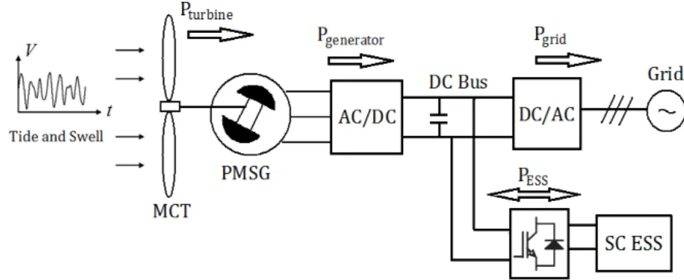
Fig. II.7. General schema for a direct-drive MCT system with ESS.…………..…...39
Fig. II.8. Cp curve of the MCT…………..……….…………..…...40
Fig.II.9. The MCT power characteristics (with power limitation operating points)……….…………..…...40
- xii -
Fig. II.10. The generator-side synchronous rotation d-q frame….…………..…...41
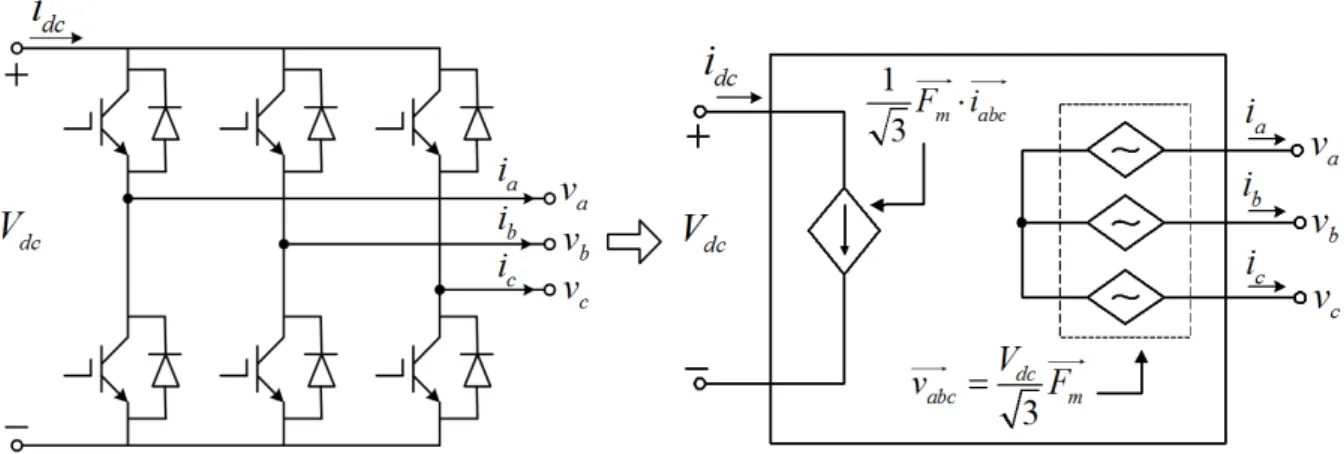
Fig. II.11. Schematic diagram and average model of a three-phase VSC.……..…...43
Fig. II.12. Control scheme of the generator-side converter…..…….…………..…...43
Fig. II.13. Open-loop generator current response in q-axis..……….…………..…...45
Fig. II.14. Open-loop generator speed response……….…………..…...46
Fig. II.15. Rotor speed reference calculated by conventional MPPT…………..…...49
Fig. II.16. Turbine and generator powers with conventional MPPT.…………..…...49
Fig. II.17. Generator powers with different filter time constants..….…………..…...51
Fig. II.18. System performances with different filter time constants.…………..…...51
Fig. II.19. Rotor speed response………….………..……….…………..…...51
Fig. II.20. Turbine and generator power with proposed MPPT (T = 7 s)…..…...52
Fig. II.21. Comparison of generator-produced power…..………….…………..…...53
Fig. II.22. Comparison of generator-produced energy..……….…………..…...53
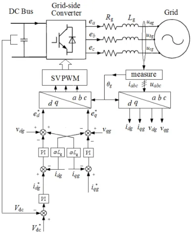
Fig. II.23. Control scheme of the grid-side converter…...………….…………..…...54
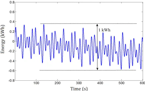
Fig. II.24. Energy changing profile of the required ESS…..……….…………...…...56
Fig. II.25. Statistical analysis of the ESS charge/discharge characteristics…...…...56
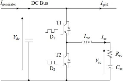
Fig. II.26. Supercapacitor and the bi-directional DC/DC converter…..………..…...57
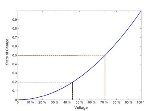
Fig. II.27. Relationship between SoC and voltage of SC ESS.…….…………..…...58
Fig. II.28. Control scheme of the bi-directional DC/DC converter....…………..…...59
Fig. II.29. Grid phase voltage and current (without the SC)….…….…………..…...61
Fig. II.30. Smoothed grid phase current by the SC………...……….…………..…...61
Fig. II.31. Voltage and current of the SC..……….…………..…...62
Fig. II.32. State of charge of the SC……….…………..…...62
Fig. II.33. Powers in different parts of the system……….…………..…...63
Fig. II.34. Energy comparison of the system……….…………..…...63
Fig. III.1. General schema for a hybrid MCT/BESS/DG system..….…………..…...68
Fig. III.2. Daily profile example: (a) tidal current speed, (b) MCT produced power and grid demand power……….…………..…...69
Fig. III.3. VRB equivalent circuit model [56]………..……….…………..…...71
Fig. III.4. The energy level change profile..……….…………..…...74
Fig. III.5. VRB voltage and current variations during a charge-discharge cycle.…...75
Fig. III.6. SoC and efficiency variation during a charge-discharge cycle…..…..…...76
Fig. III.7. Control scheme of the BESS side DC/DC converter…….…………..…...78
Fig. III.8. Powers of the MCT system with BESS during one day………..…...78
Fig. III.9. Voltage and current of the BESS.….……….…………..…...79
Fig. III.10. SoC of the BESS…….……….…………..…...79
Fig. III.11. Powers of the MCT system with BESS (initial SoC = 0.3).………..…...80
Fig. III.12. Voltage and current of the BESS (initial SoC = 0.3)..….…………..…...80
Fig. III.13. SoC of the BESS (initial SoC = 0.3)….…..……….…………..…...80
Fig. III.14. Powers of the MCT system with BESS and DG….…….…………..…...81
Fig. III.15. Voltage and current of the BESS……….…………..…...81
Fig. III.16. SoC of the BESS……….……….…………..…...82
Fig. III.17. Powers of the MCT-based hybrid system with small DG…...……..…...83
Fig. III.18. Zoom of power profiles between 12:00 and 16:00.…….…………..…...83
Fig. III.19. SoC of the BESS……….……….…………..…...83
Fig. III.20. Daily power profiles of the island case…..……….…………..…...86
Fig. III.21. Powers of the high load demand case (initial SoC = 0.5)…………..…...87
Fig. III.22. Voltage and current of the BESS (initial SoC = 0.5)..….…………..…...88
Fig. III.23. SoC of the BESS (initial SoC = 0.5)………...………….…………..…...88
Fig. III.24. Powers of the high load demand case (initial SoC = 0.25)..………..…...89
Fig. III.25. SoC of the BESS (initial SoC = 0.25).……….…………..…...89
Fig. III.26. Zoomed power curves (initial SoC = 0.25).……….…………..…...90
Fig. III.27. Zoomed BESS curves (initial SoC = 0.25)….………….…………..…...90
Fig. III.28. Powers of the low load demand case..……….…………..…...91
Fig. III.29. SoC of the BESS……….……….…………..…...91
Fig. III.30. Powers curves without the BESS……….…………..…...92
Fig. IV.1. General schema of a PMSG-based direct drive MCT system…..…..…...99
Fig. IV.2. The turbine power characteristics (§ II.3)……….…………..…....100
Fig. IV.3. Voltage and current limitation circles of the PM machine……...…..…....101
Fig. IV.4. Generator operating characteristics.……….…………..…....104
Fig. IV.5. Generator-side control scheme with flux-weakening strategy.……..…....106
Fig. IV.6. Rotor speed reference at power limitation mode.……….…………..…....107
Fig. IV.7. High tidal current speed case...……….…………..…....108
Fig. IV.8. Turbine speed responses at high tidal speed……….…………..…....109
Fig. IV.9. Generator torque responses at high tidal speed...……….…………..…....110
Fig. IV.10. Generator produced power responses at high tidal speed...………..…....110
Fig. IV.11. Marine current speed under swell effect……….…………..…....111
Fig. IV.12. Torque responses under swell effect with speed control strategy....…....111
- xiv -
Fig. IV.13. Torque responses under swell effect with torque control strategy...…....112 Fig. IV.14. Generator produced powers under the swell effect case…………..…....112 Fig. IV.15. Rotor speed responses at high tidal speed.……….…………..…....113 Fig. IV.16. Generator torque responses at high tidal speed.……….…………..…....113 Fig. IV.17. Generator produced power at high tidal speed..……….…………..…....114 Fig. IV.18. Copper losses of the generator...……….…………..…....114 Fig. IV.19. Iron losses of the generator……….…………..…....114 Fig. IV.20. Generator losses under different current velocities...….…………..…....117 Fig. IV.21. Rotor speed responses under swell effect..……….…………..…....118 Fig. IV.22. Generator produced power under swell effect...……….…………..…....118 Fig. IV.23. Generator stator currents in the d-q axis……….…………..…....118 Fig. IV.24. Generator parameters at base speed (neglecting the stator resistance)...119 Fig. IV.25. Parameters corresponding to required CPSR………….…………..…....120 Fig. IV.26. Generator power characteristics with CPSR = 1.6…….…………..…....121 Fig. IV.27. Generator power characteristics with CPSR = 2.4…….…………..…....121 Fig. IV.28. Generator power characteristics with flatter Cp……….…………..…....122
Introduction
The climate change due to greenhouse emissions and the depletion risk of traditional fossil energy resources are two great challenges faced by the entire human society. The share of renewable energy sources (such as wind, sunlight, geothermal heat, hydropower, modern biomass) in energy supply has been growing rapidly during the recent years. At least 30 nations around the world already have renewable energy contributing more than 20% of their national energy supplies. Renewable energy application will continue to grow fast in the coming decades as the sustainable development of the human society relies strongly on it.
As concerning the renewable marine energies, there exist various forms namely tidal energy, wave energy, marine thermal energy, marine osmosis energy, marine biomass energy and offshore wind energy. One of the most promising type is the tidal current energy. Indeed, the potential of electric power generated from marine tidal currents is very high. The worldwide tidal current power which is exploitable by existing technologies is estimated as 75 GW (11 GW in Europe and 3.5 GW in France). The identical power harnessing principle with wind power generation, the high power density resulting from the seawater property and the high predictability owning to the tidal astronomical characteristics make marine tidal currents particularly attractive and advantageous. During the last ten years, various original marine current turbines have been designed by different research and industrial communities and several prototypes are industrialized more than two
Introduction
- 2 -
generations of systems. The achievements in megawatt-level marine current turbine systems in Europe lead to several demonstrative marine current turbine farms which are scheduled to supply electricity for coastal areas or remote islands in the next few years.
However, there are still some difficulties before commercialization of the marine current turbine system. On the one hand, the installation cost, geographical constraints and social acceptance should be considered in planning the marine current turbine projects. On the other hand, the power fluctuations both on short-time scale (caused by swell wave disturbance) and on long-time scale (caused by the periodic variations of tidal current speed) will deteriorate the power quality or result power balance difficulties between the supply and consumption.
The main objective of this Ph.D. thesis is to simulate the whole power chain of the marine current turbine system and to investigate the utilization of energy storage systems for improving the power quality and energy management capability. Some appropriate control strategies in case of swell disturbances and over-rated marine current speed have also been analyzed in the thesis.
The contributions of this thesis are:
– Development of a simulation platform (under Matlab/Simulink®) for the marine current generation system (including swell disturbance, turbine, PMSG, converters, grid-connection part and energy storage systems) which can be used to study both grid-connected and standalone cases.
– Proposal of using supercapacitors for compensating swell-induced short-period power fluctuations; investigation of using flow battery technology for realizing daily power/energy management of the marine current turbine system.
– Proposal of an original power limitation strategy based on flux-weakening operations for PMSG-based non-pitchable marine current turbine systems at over-rated marine current speed.
This thesis is organized as follows:
Chapter I presents the up-to-date information on the achievements in megawatt-level marine
current turbine technologies; it reviews and compares various energy storage technologies concerning their applications for addressing the power fluctuation phenomena in tidal current generation systems.
Chapter II deals with the swell wave modeling and the power smoothing control strategies with
supercapacitors for a grid-connected marine current turbine system.
Chapter III proposes flow battery system for daily energy management of the hybrid marine
current turbine system with diesel generators.
Chapter IV analyses the flux-weakening strategy for power limitation control of the PMSG-based
Chapter I: State of the Art Survey of Energy Storage Technologies
State of the Art Survey of Energy Storage Technologies for
Marine Current Turbines
I.1 INTRODUCTION ... 4
I.2 TIDAL CURRENT TURBINE BACKGROUND ... 4
I.3 POWER FLUCTUATION PHENOMENA ... 10
I.4 BATTERY STORAGE TECHNOLOGIES ... 12
4.1 LEAD-ACID BATTERIES ... 13
4.2 NICKEL-BASED BATTERIES ... 13
4.3 LITHIUM-ION BATTERIES ... 14
4.4 SODIUM-SULPHUR BATTERIES ... 15
4.5 FLOW BATTERIES ... 16
4.6 BATTERY TECHNOLOGIES COMPARISON ... 17
I.5 FLYWHEEL TECHNOLOGIES... 19
I.6 SUPERCAPACITOR TECHNOLOGIES ... 21
I.7 PHS AND CAES TECHNOLOGIES... 23
7.1 PUMPED HYDRO STORAGE ... 23
7.2 COMPRESSED AIR ENERGY STORAGE ... 25
I.8 COMPARISIONS OF ENERGY STORAGE TECHNOLOGIES ... 26
I.9 CONCLUSION ... 29
Chapter
Chapter I: State of the Art Survey of Energy Storage Technologies
- 4 -
I.1 INTRODUCTION
Increasing concerns about the depletion of fossil resources and environmental issues lead to a global need for producing more clean energy from renewable sources. Ocean is appreciated as a vast source of renewable energies. Considering marine renewable energies, significant electrical powers can be extracted from marine tidal currents. However, the power harnessed from marine tidal currents could be highly fluctuant due to swell waves and the periodicity of the tidal period. To improve the power quality and make the marine turbine system produce more reliable and stable electricity to the grid/load side, energy storage systems can play a crucial role. In this chapter, a review and state of the art of energy storage technologies are presented. Various energy storage technologies are analyzed and compared. The long-period power variation due to the tide phenomenon and the short-period power fluctuation due to swell effect are both considered. The background of tidal current energy and some up-to-date information about the large current turbine technologies are also presented.
I.2 TIDAL CURRENT TURBINE BACKGROUND
Although various kinds of energy can be extracted from the sea such as tidal current energy, wave energy, thermal energy, ocean osmosis (salinity gradients) energy and biomass energy; the kinetic energy available in tidal currents can be converted to electricity using relatively mature turbine technologies. The exploitable marine current power with present technologies is estimated about 75 GW in the world and 11 GW in Europe. France has about 3.4 GW potential which places the second in European countries behind 6 GW in UK [1].
One of the main advantages of marine current energy is related to the predictability of the resource. Exploitable marine currents are mostly driven by tidal currents, which cause seawater motion twice each day with a period of approximately 12 h and 24 min (a semidiurnal tide), or once each day in about 24 h and 48 min (a diurnal tide). The astronomic nature of tides is driven by the gravitational interaction of the Earth-Moon-Sun system and makes marine tidal currents highly predictable with 98% accuracy for decades [2]. Marine current energy is in first order independent of season and weather conditions which would affect the performances of solar and wind power generation.
There are basically two ways of generating electricity from marine tidal energies: either by building a tidal barrage across an estuary or a bay, or by extracting energy from free flowing tidal currents [3]. A tidal barrage allows water to flow into a bay or river during high tide, and
Chapter I: State of the Art Survey of Energy Storage Technologies
releases the water back during low tide. Turbines can be placed at these sluices to capture the energy as the water flows in and out. The main drawback of this scheme is that suitable sites of constructing a dam-like structure are very limited worldwide. Moreover, large barrage systems would change the hydrology and may have negative impacts on the local ecosystem [4]. Therefore during the last few decades, developers have shifted towards technologies that capture the kinetic energy from tidal-driven marine currents. The power capture principle is quite similar to wind power generation system. In fact, various original horizontal axis and vertical axis marine current turbines (MCT) have been developed around the world in recent years [5-8]. The majority of MCT devices are horizontal axis turbines with rotation axis parallel to the current flow direction. The main disadvantages associated with vertical axis turbines are relative low self-starting capability, high torque fluctuations and generally lower efficiency than horizontal axis turbine design. Currently, only horizontal axis MCTs appear to be the most technologically and economically solution for large-scale marine current turbines with power capacity over 500 kW.
Several horizontal axis turbine technologies have been developed more than one generation of systems and have been chosen by the industrial community to realize pilot demonstrative MCT farms before the final commercial stage. These pilot MCT farm projects illustrate the up-to-date developments of MCT technologies which will provide electricity to coastal or island areas in the coming years. Table I.1 summarizes the main information about some of these pilot MCT farm projects and their planned/estimated operational dates.
OpenHydro is an open-center turbine technology; a 250 kW prototype was installed and tested at European Marine Energy Center (EMEC) off Orkney in Scotland and connected to the UK national grid in 2008. This turbine technology is then chosen by the French utility company EDF to build a demonstrative MCT farm off the coast of Paimpol-Bréhat in Brittany, France. The first 500 kW OpenHydro turbine (Fig. I.1) was tested in September 2011 in Brest. This 850 tonnes turbine has a diameter of 16 m and is supposed to be installed at a depth of 35 meters. The 4-turbine farm is reported to be in operation in 2014 [9].
The 1MW pre-commercial turbine HS1000 (Fig. I.2) was tested by Andritz Hydro Hammerfest (original Hammerfest Strøm) at EMEC tidal test site at the end of 2011. The HS1000 turbine is based on the technology of a smaller prototype HS300 (300 kW), which was installed in Norway and connected to the public grid in 2004. This turbine technology is planed to be used in a 10 MW commercial array in the Sound of Islay on the west coast of Scotland [14]. This technology is also reported to be chosen in the first phase of MeyGen tidal
Chapter I: State of the Art Survey of Energy Storage Technologies
- 6 -
current project in Inner Sound of the Pentland Firth [10]. Another candidate for the MeyGen project is the AR1000 turbine (Fig. I. 3) technology developed by Atlantis Resources
Table I.1. Pilot MCT farms in the coming years [1], [9-11].
Companies Location Turbine Type Turbine Number
Total Capacity (MW)
Operational Year
DCNS, EDF Paimpol Bréhat OpenHydro 4 2 2014/2015
MeyGen Pentland Firth (Scotland) HS 1000 or AR 1000 6 6 2015/2016 MCT, Siemens Kyle Rhea (Scotland) SeaGen S 4 8 2015 Anglesey (Wales) SeaGen S 5 10 > 2015 Andritz Hydro Hammerfest Sound of Islay (Scotland) HS 1000 10 10 > 2015 GDF Suez, Eole Generation
Raz Blanchard Voith Hytide 3~6 3~12 2016
Fromveur Sabella > 4 > 4 2016
Chapter I: State of the Art Survey of Energy Storage Technologies
Fig. I.2. Andritz Hydro Hammerfest HS1000 turbine [13].
Fig. I.3. Atlantis AR1000 turbine [15].
Corporation [15]. The Atlantis AR1000 turbine features fixed pitch configuration and is rated at 1 MW at 2.65 m/s current velocity. The first AR1000 was successfully deployed and commissioned at the EMEC facility during the summer of 2011. A larger turbine AR1500 (1.5 MW at 3.0 m/s) is under development for future installation in the Pentland Firth in Scotland and the Bay of Fundy in Canada.
Chapter I: State of the Art Survey of Energy Storage Technologies
- 8 -
The SeaGen S turbine developed by the Marine Current Turbine Ltd (owned by Siemens since 2012) is a well-known twin rotor technology and it is the world first grid-connected megawatt-level MCT system. The 1.2 MW SeaGen S system (2×600 kW) was installed in Strangford Lough in Northern Ireland in 2008 and has generated 8 GWh electricity since the installation [16]. The new SeaGen S system planed to be installed in the two commercial arrays in UK waters (as listed in Table I.1) will be an up-scaled version with 2 MW power rating for each unit.
French energy company GDF Suez has plans to install pilot tidal energy farms at Raz Blanchard off the coast of Lower Normandy and the Fromveur passage off the coast of Finistère in Brittany. These two sites represent 80% of the marine current energy potential in France. For the Raz Blanchard project, GDF Suez has recently confirmed to use Voith Hydro HyTide turbine and Alstom tidal turbine technology [17]. Voith turbine technology (Fig. I.4) is developed by German hydropower equipment maker Voith Company. The 1 MW fixed pitch turbine has a rotor diameter of 16 m and reaches the rated power at a current velocity of 2.9 m/s. Alstom tidal turbine (Fig. I.5) is developed with Tidal Generation Ltd and also has a power rating of 1 MW. This turbine has rotor diameter of 18 m and reaches the rated power at a current velocity of 2.7 m/s. Both two turbines are now installed at EMEC tidal test site [18-19]. For the Fromveur project, the Sabella tidal turbine technology will be used. The Sabella D10 turbine will have a rotor diameter of 10 m and a power capacity of 0.5~1.1 MW for 3.0~4.0 m/s current velocities [20]. Figure I.6 illustrates the perspective Sabella turbine farm.
Chapter I: State of the Art Survey of Energy Storage Technologies
Fig. I.5. Alstom tidal turbine [19].
Fig. I.6. Sabella turbine farm illustration [21].
The Sabella D10 is based on the first French marine current turbine Sabella D03 (3 m rotor diameter) which was tested at Odet estuary near Brest in 2008. The prototype D10 turbine is now completing the construction and is scheduled to be installed in the Fromveur passage at the end of 2014. Larger turbines D12 and D15 with power capacities of 1~2 MW are under design for future turbine farm applications [20-21].
The turbines presented above represent the newest achievements in the megawatt-level MCT technologies. The comment point is that they are all horizontal axis turbine; and it should be noted that most of them adopt the fixed pitch solution for the turbine blades.
Chapter I: State of the Art Survey of Energy Storage Technologies
- 10 -
I.3 POWER FLUCTUATION PHENOMENA
The attraction of tidal current renewable energy lies in high energy density and high predictability of the tidal current resources. Seawater is more than 830 times denser than air and it enables a MCT to be 2~3 times smaller than a wind turbine for a same power rating. Moreover, the astronomic nature of the tides makes tidal current a very predictable energy resource on long-period scale for decades. However, the MCT is subjected to two kinds of power fluctuation phenomena.
The mechanical power harnessed by a horizontal marine current turbine can be calculated by the following equation,
3
1 ρ
2 p
P= C AV (I.1) In this equation, sea water density ρ and turbine blade swept area A are considered as constants; V represents the marine current velocity; Cp is the power capture coefficient and is
related to the tip top speed ratio and the marine current speed when the blade pitch angle is fixed. For typical MCTs, Cp is estimated to be in the range of 0.35-0.5 [3]. When a Maximal
Power Point Tracking (MPPT) strategy is used, the turbine rotor speed is able to be controlled to keep Cp at its optimal value. That means in first order, the power produced by the MCT is
proportional to the cubic of current speed in the turbine cross section. It can be seen from (I.1) that the power produced by a MCT would change greatly when there are variations in the marine current speed.
Two main kinds of power fluctuations can be identified. On a daily time scale, the MCT generated power varies with a period of about 6 or 12 hours which is related to tidal astronomical phenomenon. In Europe, the semi-diurnal tide is dominant and the tidal current direction changes about every 6 hours [1]. On a much smaller time scale, the MCT power may fluctuate with a period of a few seconds caused by swell disturbances. These short-time fluctuations are mainly related to long wavelength swells which are considered as the main disturbance for the marine current turbine system.
Figure I.7 gives the measured swell waves data at Les Pierres Noires in the Fromveur passage near Brest. This correlogram of swell typical period Tp and significant height Hs is from
CANDHIS (French National Archiving Center for In-situ Swell Measurements) [22]. The data are recorded during winters in the last few years (2005-2013). There are totally 46889 records in this table. If we consider that the swells corresponding to sea states of 10 s <Tpand
s
Chapter I: State of the Art Survey of Energy Storage Technologies
Fig. I.7. Correlation diagram of swell at Les Pierres Noires [22].
It implies that non-negligible swell waves occur 71% (=33206/46889) of the time for this high potential tidal current energy site during the winter. The sea state would be relatively calmer during summer period in this site, however the swell is still considered as the main disturbance for marine current speed in this water area.
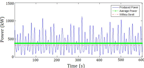
Figure I.8 gives an example of the power produced by a MCT during one day period. This calculation is based on the tidal data provided by the SHOM (French Navy Hydrographic and Oceanographic Service) for Raz de Sein. In this calculation, the Cp is set at 0.4 and the blade
swept area is calculated by π⋅82. Fig. I.8a (not considering swell effect) shows the long-time
power variation caused by tidal astronomic nature, which are highly predictable on hourly
0 4 8 12 16 20 24 0 100 200 300 400 500 600 700
Harnessed power without swell effects during 24 hours
hours p o w e r (k W ) Produced Power Average Power
Chapter I: State of the Art Survey of Energy Storage Technologies - 12 - 0 120 240 360 480 600 720 840 960 1080 1200 1320 1440 0 200 400 600 800 1000 1200
Total harnessed power with swell effects during 24 hours
minutes p o w e r (k W ) Produced Power Average Power
(b) with swell effect
Fig. I.8. Power produced by a MCT during one day.
periods for the given site. Fig. I.8b shows the power profile when considering swell effect which introduces short-time fluctuations in the power profile and makes the MCT harnessed power far away from the prediction.
Integration of variable and fluctuating renewable sources to the power grid increases the difficulties of stabilizing the power network and balancing the supply and demand. Energy storage systems (ESS) are assumed to be a good solution to smooth the power fluctuations, improve the system reliability and provide auxiliary services to the grid [23-24]. For marine current energy application, two different types of ESS should be considered [25]. For the slow power variation related to the tidal astronomical character, long duration and high energy capacity ESSs are expected. On the other hand, high power and quick charge/discharge ESS devices are required to deal with the fast power fluctuation caused by swell effect. In the following sections, a state of the art of various ESS technologies would be given.
I.4 BATTERY STORAGE TECHNOLOGIES
Battery is a classical solution for storing electricity in the form of chemical energy. Battery storage technologies presented here refer to rechargeable batteries which can be used as energy storage sources. A battery system usually consists of one cell or multiple cells connected in series or in parallel depending on the desired output voltage and capacity. Each battery cell comprises the cathode (positive electrode), the anode (negative electrode) and the
Chapter I: State of the Art Survey of Energy Storage Technologies
electrolyte which provides the medium for transfer of electrons between the two electrodes. During discharge, electrochemical reactions at the two electrodes generate a flow of electrons through an external circuit with the cathode accepting electrons and the anode providing electrons. During charging process, the electrochemical reactions are reversed and the battery absorbs electricity energy from the external circuit.
4.1 Lead-acid Batteries
Lead-acid batteries are the oldest type of rechargeable batteries. They are considered as very mature technologies. They are easy to install and have a low cost. Valve regulated lead-acid batteries require negligible maintenance. The self-discharge rates for this type of batteries are very low, around 2-5% of rated capacity per month, which make them ideal for long-term storage applications. However, disadvantages of lead-acid batteries are low energy density and short service life. The typical energy density is around 30 Wh/kg and the typical lifetime is between 1200 and 1800 cycles [26]. The cycle life would be affected by depth of discharge and they are not suitable for discharges over 20% of their rated capacity [27]. The performance of lead-acid would also be affected by temperature: higher temperature (with the upper limit of 45°C) will reduce battery lifetime and lower temperature (with the lower limit of -5°C) will reduce the efficiency.
4.2 Nickel-based Batteries
In a nickel-based battery, nickel hydroxide is used on the positive electrode but for the negative electrode different materials can be used. This fact explains the existence of various technologies. There are three kinds of nickel-based batteries namely the nickel-cadmium (NiCd) battery, the nickel-metal hydride (NiMH) battery and the nickel-zinc (NiZn) battery. The NiCd technology uses cadmium hydroxide, the NiMH uses a metal alloy and the NiZn uses zinc hydroxide. Nickel-based batteries have larger energy densities than lead-acid batteries, 50 Wh/kg for the NiCd, 80 Wh/kg for the NiMH and 60 Wh/kg for the NiZn.
NiCd batteries are now reaching the level of maturity as lead-acid batteries. NiCd batteries have a longer lifetime about 3000 cycles and can be fully discharged without damage [28]. As an example, this technology is used in the energy storage system of the Alaska Golden Valley project which provides a backup to an isolated electrical power system. This project is claimed to be the world’s most powerful battery system which can produce up to 52 MW of emergency backup power for about 15 minutes [29]. However, two drawbacks limit future large-scale deployment of this technology. One is the high price, for the NiCd battery may
Chapter I: State of the Art Survey of Energy Storage Technologies
- 14 -
cost up to 10 times more than the lead-acid battery. Another is the environment concerns about cadmium toxicity and associated recycling issues [30-31].
NiMH batteries have high energy density witch is over twice than lead-acid batteries. This type of batteries can be recycled and their components are harmless to the environment. They also can be used in large temperature ranges and high voltage operation. However, repeatedly discharged at high load currents would shorten the life of NiMH batteries to about 200-300 cycles and the memory effect reduces the useful SoC (State of Charge) of the battery. NiZn batteries have the same advantages of NiMH batteries and have deep cycle capability as NiCd batteries, but they suffer from poor life cycle due to the fast growth of dendrites.
4.3 Lithium-ion Batteries
Lithium-ion batteries achieve excellent performances in portable electronics and medical devices. This technology is now typically driven by the consumer electronics market (smartphone, tablet, digital camera, etc.) and is very attractive for electric vehicle applications, because lithium-ion batteries are lighter, smaller and more powerful than other batteries. They have the highest energy density (100-250 Wh/kg) and the highest power density (800-2000 W/kg) among all the batteries [32]. Other advantages of lithium batteries include high efficiency, low memory effect and low self-discharge rate. This is the reason why lithium-ion batteries are very promising to be used in the next-generation electrical vehicles or hybrid vehicles [27, 32-33].
Some drawbacks exist in this battery technology. Lithium-ion batteries are theoretically characterized by a lifetime about 3000 cycles at 80% depth of discharge. However in actual, lithium-ion batteries are not robust and sometimes very fragile. Life cycles are affected by temperature and would be severely shortened by deep discharges [28]. Usually, lithium-ion batteries require special protection circuit to avoid overload and need sophisticated management systems to maintain safe operational conditions. Another drawback is that the cost of lithium-ion batteries, from $900/kWh to $1300/kWh. These facts would limit the use of lithium-ion batteries in large-capacity cases and applications where low SoC would be reached.
In 2011, a 32-MW lithium-ion battery system was installed adjacent to a wind farm near Elkins in West Virginia (USA) for smoothing out some of the wind’s variability. This battery system is capable of discharging the rated power for about 15 minutes [29]. A recent research shows that lithium-ion batteries could be the most cost-effective solution for integrating renewable sources only when the required depth of discharge is limited around 10% [34].
Chapter I: State of the Art Survey of Energy Storage Technologies
4.4 Sodium-sulphur Batteries
Sodium-sulphur (NaS) is a relatively new promising high temperature battery technology, operating at over 300°C. Basic cell construction uses liquid sulphur at the positive electrode and liquid molten sodium at the negative electrode separated by a solid beta-alumina ceramic electrolyte (shown in Fig. I.9). The specific energy density of this kind of battery is 100Wh/kg and the life span is 2500 cycles at 100% depth of discharge with a high energy efficient about 89% [28].
Fig. I.9. NaS battery cell and package [23],[35].
During discharge when positive Na+ ions flow through the electrolyte and combine with the sulfur forming sodium polysulfide (Na2S4), electrons will flow in the external circuit of the battery. Basic cell voltage is about 2V. This process is reversible: during the charging process, the Na2S4 molecules release the Na+ ions to the electrolyte where these ions are recombined as elemental sodium. In classical operating conditions, the heat produced by charging and discharging is enough to maintain running temperatures (about 300-350°C), but the battery still need to be heated in stand-by mode to keep the electrodes in molten state [36].
Sodium sulfur battery technology was brought to market in 2002 by Japanese company NGK. To date, more than 270 MW of total capacity has been set up at over 190 sites in Japan. These batteries stored energy which is suitable for 6 hours of daily peak shaving. U.S. utilities have deployed 9 MW of NaS batteries for reinforcing wind capacity and other applications. The largest NaS installation is a 34 MW, 245 MWh unit used for wind stabilization in Northern Japan [31].
On one hand, this technology has advantages such as low cost, high energy capacity, high efficiency and deep discharge tolerance. On the other hand, this battery technology is
Chapter I: State of the Art Survey of Energy Storage Technologies
- 16 -
penalized by high operating temperature and the corrosive nature of sodium. These characteristics make NaS batteries suitable for large-scale stationary applications. This technology appears attractive for marine renewable applications, being an effective solution for stabilizing energy output during periods of 3-6 hours in order to smooth the output of a marine generator farm. However the operating environment must be perfectly controlled if this solution is used. This fact implies ‘a priori’ a setup on an offshore platform or near the onshore transmission line for the power gird.
4.5 Flow Batteries
Flow batteries are relatively new battery technology dedicated for large energy capacity applications. This technology uses two external tanks to reserve liquid electrolytes and a pump system for circulating the electrolytes to the battery cell stack (consisting of the two electrodes and the ion exchange membrane). Figure I.10 illustrates the structure of a flow battery system. The charging and discharging processes are realized by means of a reversible electrochemical reaction between two liquid electrolyte reservoirs. Flow batteries are often called redox flow batteries (RFB), because this technology is based on the redox (reduction-oxidation) reaction between the two electrolytes in the system.
Fig. I.10. Flow battery structure [30].
The most distinguished advantage of flow battery technologies is that the power and energy ratings can be sized independently [36-38]. The power rating is determined by the design of the electrode cells and the energy capacity depends on the volume of the electrolytes which are separated from the cell stack and can be designed independently. Therefore, flow battery can be easily designed to meet specific energy capacity or power rating requirements. These characteristics make them suitable for a wider range of applications than conventional
Chapter I: State of the Art Survey of Energy Storage Technologies
batteries. Another significant advantage is the long service life over 10,000 cycles at 75% depth of discharge. Other advantages include high safety, negligible degradation for deep discharge and negligible self-discharge. The major disadvantages of flow batteries are that the power/energy density is relative low compared to other technologies and extra pumps systems are needed.
Over the past 20 years, four designs of flow batteries have been demonstrated: vanadium redox (VRB), zinc bromine (ZnBr), polysulphide bromide (PSB) and cerium zinc (CeZn). Major installations are in Japan and North American, using the vanadium redox and zinc bromine designs. Energy efficiency is about 85% for VRB system and 75% for ZnBr system. 5kW/20kWh Community Energy Storage units based on ZnBr batteries are now being tested. Integrated ZnBr energy storage systems have been tested on transportable trailers (1MW/3MWh), and these systems could be connected in parallel for more powerful applications [31]. VRB system of 500 kW, 10 hours (5 MWh) was installed by Sumitomo Electric Industries (SEI) in Japan for peak shaving and UPS applications in 2001. The largest VRB plant so far is the 4MW/6MWh plant in Hokkaido, Japan [38]. This VRB plant can provide a temporary overload up to 6 MW and it is intended for smoothing output power fluctuations of a nearby 30.6 MW wind power plant.
Flexibility of energy and power sizing, long lifetime, low cost and low maintenance make flow battery a very promising technology to be used for integrating fluctuant and intermittent renewable energies to the power grid. For marine current energy, flow batteries can be designed differently for compensation short-time and long-time fluctuations, and more favorably they are suitable for hours energy storage for smoothing the fluctuation due to tidal phenomenon or realizing some energy management strategies.
4.6 Battery Technologies Comparison
Table I.2 summarizes the main merits and demerits for the battery technologies discussed above. For marine energy application, these batteries are reasonable supposed to be installed underwater or on an offshore platform and they may be discharged deeply in order to achieve a required smooth effect. In the first place, low maintenance and robust long service life (deep discharge ability) should be considered as important criteria, and in that term the lead-acid and lithium-ion batteries are not favorable due to their short cycle life for deep discharge. Low cost should also be emphasized, which make lithium-ion and nickel-based batteries not attractive for megawatt-scale applications.
Chapter I: State of the Art Survey of Energy Storage Technologies
- 18 -
Table I.2. Battery Technologies Comparison.
Battery Type Advantages Disadvantages
Lead-acid √Low cost √Low self-discharge (2-5%per month)
×Short cycle life (1200-1800 cycles) ×Cycle life affected by depth of charge ×Low energy density (about 40Wh/kg)
Nickel-based √Fully charged (3000 cycles) √Higher energy density (50-80Wh/kg) ×High cost, 10 times of lead acid battery ×High self-discharge (10% per month)
Lithium-ion
√High energy density (80-190Wh/kg) √Very high efficiency 90-100% √Low self-discharge (1-3% per month)
×Very high cost (900-1300 $/kWh) ×Life severely shorten by deep discharge ×Special overcharge protection circuit
NaS
√High efficiency 85-92%
√High energy density (100Wh/kg) √No degradation for deep charge √No self-discharge
×Keep heated in stand-by mode at 325℃
Flow battery
√flexible energy and power ratings √Long service life (>10,000 cycles) √No degradation for deep charge √Negligible self-discharge
×Medium energy density(40-70Wh/kg)
It can be concluded that NaS batteries and flow batteries are two best candidates among battery technologies. They are cost-effective for MW and MWh applications and they have robust service life compared with other technologies.
Compared with NaS batteries, flow batteries have a longer life span but a more complicated system set-up. Flow batteries are easier to operate because they do not need to be kept at a high temperature. With appropriate installations, flow batteries and NaS batteries seem to be two most promising battery technologies suitable for smoothing the long-term variation in marine current energy systems.
For the short-term fluctuation (caused by swell disturbance) with a period of seconds, a much shorter charge/discharge cycle time than batteries is required. Two short-term energy storage technologies with typical charge/discharge time constant about seconds to minutes are presented in the following sections.
Chapter I: State of the Art Survey of Energy Storage Technologies
I.5 FLYWHEEL TECHNOLOGIES
A flywheel is based on a rotating disk which can store kinetic energy. This flywheel is associated with an electrical machine and drive system which allows controlling the energy storage and discharge. According to the rotational speed, there are broadly two classes of flywheel technologies: low-speed flywheels (less than 10,000 rpm) and high-speed flywheels (more than 10,000 rpm) [39-41]. Low-speed flywheels use steel rotors and conventional bearings, and they achieve energy density of 5-30 Wh/kg. High-speed flywheels use composite rotors and low friction bearings (e.g., superconducting magnetic bearings). Composite rims are lighter and much stronger than steel, so they can be used with extremely high rotational speed and achieve high energy density up to 100 Wh/kg [26]. The amount of energy stored in a flywheel depends on the square of the rotational speed, making high-speed flywheels highly desirable for energy/mass ratio optimization.
Figure I.11 shows a typical flywheel energy storage system (FESS). It consists of a massive rotating cylinder (a rim attached to a shaft) that is supported on a stator by magnetically levitated bearings. The flywheel system is operated in a vacuum chamber to reduce friction and losses. A motor/generator is connected to the flywheel to interact with the power grid or the renewable energy sources through power electronics drive.
Conventional low-speed flywheels can be used for the uninterruptible power supply (UPS). One of the popular flywheel UPSs is the Piller’s POWERBRIDGE system available in the range of 250-1300 kW. The bigger system contains a low-speed flywheel with a maximum speed of 3600 r/min and can deliver 1.1 MW during 15 seconds [39].
Chapter I: State of the Art Survey of Energy Storage Technologies
- 20 -
Fig. I.12. Evolution of Beacon POWER Flywheel Systems [35].
Figure I.12 illustrates the evolution of Beacon POWER FESS products and provides a clear insight into the two applications where FESS can offer. Low-power systems (several kW for hours) are used for telecommunication equipment support. High-power systems (hundreds of kW for seconds or minutes) can be used to provide power frequency regulation service for the power grid. An example of this typical grid-application is the 20 MW flywheel plant which provides frequency regulation service to the local grid in Stephentown, NY. The commercial operation of this facility started in 2011 [41]. FESSs are also being used in isolated power grid. For instance, a 350 kW / 5 kWh FESS is installed in Flores Island, Portugal, for improving frequency stability of the micro-grid on the island and a 500 kW / 5 kWh FESS is used to smooth the power fluctuations in a 3 MW wind-diesel hybrid system in Coral Bay, Australia [42].
Key advantages of flywheel energy storage system include high cyclic ability (over 105 cycles with deep discharge or 20 years service time), high power density (quick charge/discharge), high efficiency and low maintenance. One of the main disadvantages of flywheel energy storage system is the high self-discharge rate which is typically over 20% per hour [43]. This disadvantage makes them not suitable for long-term applications. Another challenge is to reduce the high system price due to advanced materials and limited mass production.
Chapter I: State of the Art Survey of Energy Storage Technologies
Based on these characters and the development trends, flywheels seem very appropriate for providing short-term ride-through power or smoothing the power fluctuations on a time scale of 15 seconds to 15 minutes. With regard to long-term energy storage, they don’t have many advantages over battery systems. Therefore, for marine current energy application, flywheel systems can become a very interesting candidate to compensate short-term fluctuations related to swell effects. It should be noted that flywheel systems are not easy to be installed underwater considering the corrosion effects of sea water and the peripheral equipments such as power converters and transformers.
I.6 SUPERCAPACITOR TECHNOLOGIES
Supercapacitors, also know as ultracapacitors and electrochemical double-layer capacitors (EDLCs), store energy by the capacitance effect. Supercapacitors are working in a similar way as conventional capacitors, but they are characterized by a much higher capacitance (kilo farads) in smaller packages [23]. It must be remembered that the capacitance is proportional to the area of the plates and the permittivity of the dielectric, and inversely proportional to the distance between the plates. Supercapacitors use high-permittivity dielectric and maximize the electrode surface area by using porous active carbon, thus allowing large amount of energy to be stored at the electrode surface. The two electrodes are separated by a very thin porous separator witch is immersed in the electrolyte. The electrolyte can be either aqueous or organic. The aqueous capacitors have a lower energy density due to a lower cell voltage but are less expensive. They have a lower resistance, and work over a wider temperature range. Figure I.13 shows the structure of one individual supercapacitor cell [44]. The potential difference for one cell is around 1V and 3V with aqueous and organic electrolyte respectively.
Chapter I: State of the Art Survey of Energy Storage Technologies
- 22 -
Thanks to that the electrodes will not be chemically degraded as in batteries, supercapacitors are able to be used during hundreds of thousands cycles in deep charge/discharge operations. Supercapacitor can be cycled more than 500,000 times and have a service life of 12 years. Power density of supercapacitors is considerably higher than batteries due to that the electrical charges are physically stored on the electrodes. Supercapacitors can be easily charged and discharged in seconds, much faster than batteries. Energy efficiency is high and no heat or hazardous substances are released during operation. Although new materials for electrodes are being developed for increasing the energy density, supercapacitors are limited by the disadvantages of a very low energy density (5 Wh/kg) and a high self-discharge rate. That means supercapacitors can absorb or release high amount of power only during a very short time period. Another point is that the lifetime of supercapacitor would be affected by the variation of voltage and by the temperature, so the design of supercapacitor system should include an aging model taking into account the operation characteristics.
Common applications of supercapacitors include starting diesel trucks, railroad locomotives and actuators [45]. Another typical application for supercapacitors is hybrid electric vehicles (HEV). They are used in HEV for storing energy from electrical braking and for providing transient high load power due to their fast charge and discharge capability. Using supercapacitors in conjunction with batteries combines the high power characteristic of the supercapacitor and the high energy capacity of the battery. In a HEV, the use of supercapacitors allows extending the life of the battery (by reducing the depth of charge/discharge of the battery) and enables the battery to be downsized (by reducing the peak loads on the battery) [46-48]. A recent research shows that hybrid supercapacitor/battery design can achieve a substantial reduction in the overall ESS cost in HEV application [33]. Researches have also shown that supercapacitors can be used to absorb high-frequency power fluctuations produced from renewable energy sources, improving significantly power qualities of renewable energy generation systems. Supercapacitors for Doubly-fed Induction Generator (DFIG) and Permanent Magnet Synchronous Generator (PMSG) wind turbine applications are discussed in [49-50] and [51] respectively. In [52-54] only battery is used as the ESS, the main objection is to balance the difference between the turbine-produced power and the load (or grid) required power. If high-power fluctuations have to be smoothed, high-power density devices such as supercapacitors are therefore required. Hybrid ESS based on battery and supercapacitor for wind power application are studied in [55-57].The aim of hybrid ESS is to absorb high-frequency fluctuations by supercapacitors and let batteries dealing with low-frequency fluctuations. This will allow optimizing high-power and high-energy ESSs.
Chapter I: State of the Art Survey of Energy Storage Technologies
Supercapacitors used in photovoltaic applications are presented in [58-59]. In reference [60], a solution using supercapacitors for smoothing the power generated from SEAREV wave energy converter is presented; and different SoC control strategies for the supercapacitor bank are studied and compared.
For marine current energy system, both low-frequency (long-term) and high-frequency (short-term) fluctuations exist. Thanks to high power performance and high cycling capability, the supercapacitor technology appears to be one of the most appropriate solutions for smoothing the high-frequency fluctuations. But supercapacitors are not adapted for smoothing the power on a time scale larger than one minute. It means that high energy density and long-duration energy storage devices are needed to be associated with supercapacitors for a global treatment in marine current application.
I.7 PHS AND CAES TECHNOLOGIES
Megawatt-level MCTs would facilitate the tidal current energy application and increase the need of energy storage system in the near future. The energy storage technologies presented in the previous sections can easily handle the needs for a single MCT turbine or a small MCT farm with a power range of several MWs. However, larger MCT farm installation can still be envisaged in the long term development of renewable energy application. For example, the possibilities of constructing a MCT plant with 100 turbines in France and deploying a 100 MW MCT farm off the southern most tip of the Orkney Islands Scotland are mentioned in [61] and [62] respectively. Although these large MCT farm will probably be constructed around 2020, the challenge of bulk energy storage requirement for compensate long-term tidal current energy variation can not be neglected. A recent research in [63] shows that even a portfolio approach of aggregating tidal current energies from different locations can not sufficiently compensate the power variation problem caused by the tidal periodicities.
Concerning large-scale grid-level energy storage applications, pumped hydro storage (PHS) and compressed air energy storage (CAES) are two important technologies.
7.1 Pumped Hydro Storage
Pumped hydro storage is a well-known technology of storing and producing electricity by the use of pumps and turbines to transfer water between two reservoirs situated at different heights. During low electricity demand periods, excess generated energy is used to pump the
Chapter I: State of the Art Survey of Energy Storage Technologies
- 24 -
water from the lower reservoir to the upper reservoir (Fig. I.14). During the peak hours when load demand is high, the water is released back to the lower reservoir through hydro turbines, generating electricity. The round-trip efficiencies of PHS plant are over 75%. The storage capacity of PHS depends on two parameters: the height of the waterfall and the volume of the water. Sites with two natural bodies of water are favorable for this technology and the sea can be used as the lower reservoir. The low energy density of the whole system requires either very large bodies of water or a large height between the two reservoirs. Generally, the lifetime of a PHS is over 30 years with a round trip efficiency of 65-75%. The capital costs are about 650-1900 $/kW and 15-20 $/kWh [65].
Pumped hydro storage technology is the most widespread energy storage system used for electricity networks, with about 300 systems operating worldwide. Their main applications are providing energy management, frequency control, and reserve capacity. PHS is now the only energy storage technology deployed on a GW scale worldwide [66]. In the United States, about 20 GW are deployed in 39 sites, with capacities from less than 50 MW to 2,100 MW. Many of these sites are able to store the excess power during more than 10 hours, making the technology favorable for load leveling. The fast time response (switching between pumping and generating can occur within minutes) enables this technology to provide frequency control for the electricity network. However, the drawbacks for this technology are that the implementation of such a system needs an appropriate geographic site, a high cost investment, and a long construction time.
![Fig. I.2. Andritz Hydro Hammerfest HS1000 turbine [13].](https://thumb-eu.123doks.com/thumbv2/123doknet/14526419.723040/24.892.186.708.105.483/fig-i-andritz-hydro-hammerfest-hs-turbine.webp)
![Fig. II.2. Ratio of magnitudes between the second term and the first term in the second-order Stokes model [72]](https://thumb-eu.123doks.com/thumbv2/123doknet/14526419.723040/53.892.247.658.115.409/fig-ratio-magnitudes-second-second-order-stokes-model.webp)