HAL Id: tel-00408687
https://tel.archives-ouvertes.fr/tel-00408687
Submitted on 31 Jul 2009HAL is a multi-disciplinary open access archive for the deposit and dissemination of sci-entific research documents, whether they are pub-lished or not. The documents may come from teaching and research institutions in France or abroad, or from public or private research centers.
L’archive ouverte pluridisciplinaire HAL, est destinée au dépôt et à la diffusion de documents scientifiques de niveau recherche, publiés ou non, émanant des établissements d’enseignement et de recherche français ou étrangers, des laboratoires publics ou privés.
Hahnsang Kim
To cite this version:
Hahnsang Kim. An authentication architecture for cross-domain mobility. Networking and Internet Architecture [cs.NI]. Institut National des Télécommunications d’Evry, 2006. English. �tel-00408687�
Acknowledgements
First of all, I would like to respectfully express my sincere gratitude to Dr. Isabelle CHRIS -MENT, Maˆıtre de Conf´erence at the Univercit´e Henri Poincar´e and Dr. Refik MOLVA,
Professor Class 1 at the Institut Eur´ecom for being the rapporteurs of my thesis.
I wish to thank Dr. Kaisa NYBERG, Professor in the Department of CSE at Helsinki University of Technology, Finland; Dr. Pascal URIEN, Professor at Group des Ecoles des T´el´ecommunications-Telecom Paris (GET-ENST); and Dr. Jos´e ARAUJO, Research project
manager in the French Research and Innovation Centre of Alcatel, for being interested in my work and for joining the committee examining my thesis.
I am deeply indebted to Dr. Kang G. SHIN, Professor in the Department of CS and the Founding Director of the Real-Time Computing Laboratory at the University of Michigan, U.S.A., for his guidance and invaluable comments.
Profound gratitude is due to Dr. Hossam AFIFI, Professor at the Institut National des
T´el´ecommunications-Evry Universit´e (INT-Evry) who supervised my thesis. His constant encouragement enabled me to successfully complete it.
I will forever appreciate the efforts of Dr. Walid DABBOUS, Directeur de Recherche at INRIA who made available all the means necessary for my work in the projet Plan`ete while advising me.
I am extremely fortunate to have worked with Dr. Thierry TURLETTI, Charge de
Recherche at INRIA who inspired me with his encouraging research efforts in the initial stages of my work at INRIA.
I am grateful to all the members of the projet Plan`ete at INRIA, including Dr. Thierry PARMENTELAT, for their social and technical assistance; Dr. Robert DE SIMONE,
Di-recteur de Recherche at INRIA for his genial interest in my work; Dr. Emmanuel L ´ETY,
Research engineer at UDcast for his considerate comments; and Dr. Jin-Young CHOI,
Pro-fessor at Korea University for his endless support and help.
Finally, this thesis is dedicated to my mother whose constant, perpetual love is always in my heart and to whom I wish to extend my heartfelt thanks.
R´esume
L’´evolution des technologies sans fil favorise de plus en plus la mobilit´e, mais il reste cependant des probl`emes non r´esolus li´es `a la s´ecurit´e. Le changement de contexte d’un r´eseau `a l’autre n´ecessite des proc´edures qui infligent du d´elai li´e aux proc´edures ‘r´eseau’ ainsi qu’au changement de lien. La s´ecurit´e ´etant requise dans les deux changements. La proc´edure d’authentification `a un grand impact sur le d´elai de l’´etablissement du lien. Cela est encore plus tangible pour une authentification `a travers plusieurs domaines. Il en sort que la conception de syst`emes d’authentification rapides qui ne compromettent pas le niveau de s´ecurit´e est un grand challenge. Dans cette th`ese, je propose de mani`ere g´en´erale une solution permettant la minimisation de cette latence. L’architecture est d´ecompos´ee en trois contributions. La premi`ere partie se focalise sur une architecture d’authentification d´ecentralis´ee. Nous introduisons la notion de ‘proxy’ qui permet de r´eduire les couts en terme de d´elai entre points d’acc`es. Le r´esultat est un m´ecanisme permettant de trouver l’endroit de placement optimal dans une architecture arborescente pour minimiser le nom-bre de messages. Dans la seconde partie, nous proposons un protocole d’estimation de la mobilit´e (MAP) et de pr´eparation au changement. Cette partie est essentiellement d´edi´ee `a des mobilit´e inter-domaine, coop´erant avec les agents de d´eput´e. La troisi`eme partie traite d’un m´ecanisme dans l’acc`es qui permet `a des routeurs de bordure de pr´eparer le contexte avant le changement afin encore une fois de r´eduire les latences. On se base sur des mod`eles
th´eoriques de pr´ediction bas´es sur des arbres de pr´ediction et des estimations statistiques des trajets.
Abstract
The rapid growth of wireless device technologies is enabling seamless mobility, but there are still major concerns related to the performance of security. The handoff performance correlates with inter-wireless link switch latency and network layer latency, with security being required at both levels. Authentication latency has a significant impact, especially on the link switch phase, in the case of cross-domain mobility because of the requirement of remote contact with a home authentication server. Providing a solution to minimize the la-tency impact without degrading the level of security is a major challenge. In this thesis, we propose a high-performance authentication architecture to tackle the latency problem in fast inter-domain handoffs. The architecture consists of three contributions. First, we present a decentralized authentication scheme by introducing a ‘deputy’ agent in control of a group of access points. The collaborating deputy agents considerably reduce long-distance traffic of authentication messages. Then, we propose a mobility-adjusted authentication proto-col (MAP) dedicated to cross-domain handoffs, cooperating with the deputy agents. The protocol leverages the concept of ‘security context’ to achieve minimum handshakes so that one can significantly reduce the authentication latency. Finally, we design a security context router (SCR) that extends the deputy agent to manage security contexts. The SCR realizes seamless cross-domain mobility with the predictive forwarding of security con-text that is characterized by approximate pattern matching and statistical estimation. The
contributions made by this thesis have transparently led to significant improvements in the performance of handoff processes without compromising high-level security.
Contents
DEDICATION iii ACKNOWLEDGEMENTS iv R ´ESUME vii ABSTRACT ix 1 Introduction 1 1.1 Motivation . . . 11.2 Overview of Mobile Wireless Security . . . 3
1.3 Requirements . . . 4
1.4 Defined Entities . . . 6
1.5 What We Achieved . . . 7
1.6 Main Contributions . . . 8
1.7 Thesis Outline . . . 10
2 The State of the Art 13 2.1 The IEEE 802.11i Standard . . . 13
2.1.1 The IEEE 802.11 Association . . . 14 xi
2.1.2 The IEEE 802.1X . . . 15
2.1.3 Authentication Authorization Accounting . . . 16
2.1.4 EAP-based Authentication Protocols . . . 18
2.1.5 4-Way Handshake . . . 19
2.1.6 Group-key Handshake . . . 23
2.1.7 Fast Authentication . . . 23
2.2 Authentication in 3GPP . . . 25
2.3 The Integration of WLAN and GPRS . . . 26
3 Decentralized Authentication Architecture 31 3.1 Introduction . . . 31
3.2 AAA-UMTS Application . . . 32
3.2.1 Evaluation of the AAA-UMTS Application . . . 35
3.3 Decentralized Authentication Scheme . . . 38
3.3.1 Mobile Authentication . . . 39
3.3.2 An Abstract Model . . . 40
3.4 Performance Evaluation . . . 43
3.5 Related Work . . . 45
3.6 Conclusions . . . 46
4 Mobility-adjusted Authentication Protocol 47 4.1 Introduction . . . 47
4.2 Overview of Authentication Mechanism and Requirements . . . 49
4.2.1 The IEEE 802.11i Authentication . . . 49
4.2.2 Cross-domain-related Protocols . . . 50
CONTENTS xiii 4.2.4 BAN Logic . . . 54 4.3 MAP . . . 56 4.3.1 Architecture . . . 57 4.3.2 Communication between SCRs . . . 58 4.3.3 Authentication . . . 59 4.3.4 Defined Keys . . . 59 4.3.5 Defined Messages . . . 61 4.3.6 Message Exchanges . . . 61 4.4 Security Considerations . . . 68 4.4.1 Protocol Analysis . . . 68 4.4.2 Possible Attacks . . . 71 4.5 Performance Evaluation . . . 73 4.5.1 Simulation Methodology . . . 73
4.5.2 The Simulation Model . . . 74
4.5.3 The Simulation Results . . . 76
4.5.4 Comparison with Other Protocols . . . 79
4.5.5 Storage Overhead . . . 81
4.6 Related Work . . . 82
4.7 Conclusions . . . 83
5 Security Context Router 85 5.1 Introduction . . . 85
5.2 System Description . . . 88
5.2.1 Security Context . . . 88
5.2.3 Multi-tier and Overlay Networks . . . 89 5.3 System Model . . . 91 5.3.1 Network Model . . . 91 5.3.2 Mobility Model . . . 92 5.3.3 Edit distance . . . 97 5.3.4 Pattern Classification . . . 97 5.4 Design of SCR . . . 99
5.4.1 Data Sets with Access Functions . . . 99
5.4.2 Functional Modules . . . 102
5.4.3 Reduction in Storage Overhead . . . 108
5.5 Evaluation . . . 109 5.5.1 Evaluation Methodology . . . 110 5.5.2 Evaluation Results . . . 111 5.5.3 Numerical Analysis . . . 114 5.6 Related Work . . . 117 5.7 Conclusions . . . 120
6 Conclusions and Recommendations 123 6.1 Conclusions . . . 123
6.2 Recommendations for Future Research . . . 124
6.3 Closing Remarks . . . 125
List of Figures
1.1 An authentication scheme for the integrated networks . . . 8
2.1 An example of relevant protocol stacks in the IEEE 802.1X . . . 19
2.2 EAP message exchange . . . 20
2.3 An example of the 4-way handshake . . . 22
2.4 An example of preauthentication . . . 24
2.5 Proactive key distribution . . . 25
2.6 An integrated authentication system . . . 28
2.7 An example of successful SIM-based mobile authentication . . . 29
3.1 Inter-domain authentication via Diameter over UMTS . . . 36
3.2 Comparison of authentication latency . . . 37
3.3 Increase in authentication latency as the distance grows . . . 38
3.4 Mobile authentication scenario . . . 39
3.5 An abstract model for quantifying the cost of message exchanges . . . 40
3.6 Comparison of cost with various gs as l grows when N = 10 . . . 44
3.7 Evaluation of optimal position for the deputy server (N = 10) . . . 45
4.1 Message exchanges in the IEEE 802.11 and .11i systems . . . 50 xv
4.2 Message exchanges for a remote access grant in Kerberos . . . 51
4.3 An example of message exchanges in symmetry-key-based NS protocol . . 53
4.4 Authentication architecture . . . 58
4.5 Defined keys hierarchy and boundary . . . 60
4.6 The simulation model for inter-domain handoffs . . . 75
4.7 Authentication latency variations in different configurations of foreign servers 77 4.8 Cumulative distributions of authentication latency . . . 78
4.9 System storage availability affected by the authentication occurrence ratio . 79 4.10 End-to-end domain distance vs. authentication latency . . . 80
4.11 CPU utilization . . . 81
4.12 Latency comparison of MAP with MNS and Kerberos . . . 82
5.1 Multi-tier access and overlay networks . . . 91
5.2 A grid of access networks . . . 92
5.3 Anchor-based determination of directions . . . 93
5.4 Comparison of a variety of distributions . . . 96
5.5 An SCR architecture . . . 100
5.6 Estimate of forwarding . . . 105
5.7 The effectiveness of ahead-of-time forwarding . . . 112
5.8 Comparison of pattern recognition with various distributions . . . 113
5.9 Pattern classification and predictions . . . 115
5.10 Soft state vs storage overhead . . . 116
5.11 The results of statistical estimate from four plausible distributions . . . 118
List of Tables
4.1 Throughput of hash/symmetric and asymmetric algorithms . . . 74 5.1 Comparison of a weight-imposed method with Liu’s and generic methods . 106 5.2 Parameters used in evaluation . . . 110
Chapter 1
Introduction
1.1
Motivation
Inter-wireless technologies, ranging from IEEE 802 networks, such as Wi-Fi, WiMax and personal area network to non-802 networks, such as cellular networks, are rapidly con-verging. This allows mobile users carrying a multimedia-access device to roam across inter-technology-based networks. For instance, a mobile user currently associated with a cellular network can move and switch into wireless local area networks (WLANs) and vice versa. Time-sensitive applications, such as Voice over IP (VoIP) or video streams, are now possible over WLANs such as those based on the IEEE 802.11 Standard [7]. We anticipate, furthermore, that mobile users will soon be able to cross the border of different domains without disrupting their on-going application sessions. We use the term ‘domain’ to refer to a functionally independent group of components which form an administration unit or provide a particular wireless technology access service.
Security concerns are of paramount importance to widespread seamless mobility. The handoff performance correlates with inter-wireless link switch latency and network layer
latency — with security being required at both levels. Significant research [56, 57, 66, 75] on reducing link switch latency has been done. In contrast, authentication latency varies with mobility. When the mobile user moves around near the centralized server the latency can be minimal, while roaming away from the server can result in considerable latency. The authentication latency has a significant impact especially on the link switch phase in the case of cross-domain mobility because it requires remote contact with a home authentication server. An application for VoIP, for instance, requires the completion of a handoff in less than 50ms for acceptable Quality-of-Service (QoS) [76]. Note that the execution of a securing phase is essential as part of a secure handoff mechanism. When the technology curve regarding link switch latency reaches the limit, the authentication latency will become a dominating factor. Clearly, providing a solution to minimize the latency impact without compromising high-level security is a big challenge.
When the mobile node (MN) crosses the domain boundary, authentication latency prob-lems involve a number of factors ranging from the authentication scheme to linking mech-anisms between heterogeneous end-systems. For example, message signaling latency re-quires inter-domain authentication schemes, the efficiency of relevant authentication proto-cols, and security-relevant resource allocation among heterogeneous end-systems. An MN registers initially with its home authentication server. The server then creates the MN’s
credentialincluding private information for authentication, authorization and accounting (AAA) [1]. When the MN roams to a foreign domain, it is bound to the foreign server. An authentication request is forwarded to the MN’s home server which then verifies its identity (ID), whereas normal authentication requests in the home domain are handled locally with-out contacting any remote server. The remote contact, caused by the MN’s cross-domain handoff, incurs a significant authentication latency that is part of the handoff latency. The need to avoid such remote contact has been stated in [49].
1.2. Overview of Mobile Wireless Security 3 To sum up, the target environment we consider is the wireless access networks com-bined with WLANs and cellular networks. In such an environment, when the MN crosses the domain boundary and roams around in a foreign domain with ongoing sessions run-ning on the mobile device, the efficiency of the cross-domain authentication system is critical for the real-time performance of the system. In this thesis we present a high-performance authentication architecture to address such latency problems, supporting se-cure, cost-effective, and scalable cross-domain handoffs.
1.2
Overview of Mobile Wireless Security
Two technologies (i.e. WLAN and cellular networks) specify an authentication mechanism. The WLAN authentication system is based on the IEEE 802.11i Standard [12], while the global system for mobile communications (GSM) uses a subscriber identity module (SIM) for authentication (vs. the universal mobile telecommunications system (UMTS) which uses a universal SIM (USIM)). The following is a brief overview of each mechanism, the details of which will be presented in Chapter 2.
The IEEE 802.11i is an improvement on the IEEE 802.11 Standard specifying security mechanisms for WLANs. The goal of the 802.11i authentication is to secure a wireless link that will be established between a legitimate mobile device and access points. The
supplicantin the mobile device sends the request via an extensible authentication protocol (EAP) to the authenticator, residing on the access point. The authenticator encapsulates and forwards the request via a specified back-end authentication protocol to the authentica-tion server. In the server, the supplicant’s ID is verified in cooperaauthentica-tion with an EAP-based authentication protocol. The supplicant and server exchange a series of messages via the authenticator. In case of a successful authentication, they generate a pair-wise master key
and, in particular, the server transfers the key to the authenticator via a secure channel e.g. IPsec [42,78]. In turn, the authenticator and supplicant generate a pair-wise temporary key, based on the pair-wise master key with which to protect their communication link.
There are three important units in the authentication of cellular networks [60]: a home location register (HLR) is a database used to store permanent data about subscribers, their service profile, location information and activity status; a visitor location register (VLR) is a database that contains temporary information on subscribers and when the mobile user roams into a new area it contacts an appropriate HLR; and an authentication center (AuC) provides authentication and encryption parameters. Authentication uses a challenge-response mechanism. A SIM (USIM) runs on the mobile user’s device for the authentica-tion of the GSM (UMTS). The SIM stores network state informaauthentica-tion such as the mobile user’s current location area ID. Each SIM is uniquely identified by its SIM serial num-ber, i.e. a 19 or 20 digit unique number identifying an individual SIM card. Note that SIM-based mechanisms authenticate mobile devices rather than mobile users.
1.3
Requirements
The following is required to design a high-performance authentication architecture for cross-domain mobility.
• Signaling latency in authentication requests must be minimal. The conventional authentication architecture, i.e. a client-server model, requires all requests to eventually be processed by a single server. In such a scheme, unexpected
authentication failures, even for legitimate users, may occur due to authentication traffic congestion. Moreover, remote requests generated in a foreign domain incur a fundamental delay that may increase in proportion to geographical distance between
1.3. Requirements 5 the client’s home domain and foreign domain. Therefore, the message delays, due to geographical distance transmission delays, must have a minimal impact on fast handoffs with an acceptable QoS. A means to minimize these delays is to use an appropriate local ‘agent’ as a ‘proxy’ for the remote authentication server. However, such agents, as opposed to current AAA-defined agents, are expected to undertake part of the server’s authentication policy. In this context, how efficiently the agents are organized is important for high-performance handoffs.
• An authentication system operates in coordination with an authentication protocol defined by the particular service. When the mobile users cross domain boundaries, an appropriate authentication protocol that supports inter-domain authentication is essential. This implies the need for interaction among the mobile user, the server in the visited domain, the server in the domain in which the mobile user has previously resided and the home server. Moreover, such protocols must also support mutual authentication because the mobile user needs to ensure that the corresponding server in a foreign domain is legitimate. Conventional authentication protocols cannot be applied straightforwardly to inter-domain authentication. In such an inter-domain authentication, the protocol requires an efficient message-handshake mechanism since cross-domain message signaling is critical to the performance.
• The authentication server authenticates the mobile, based on its credentials. Provided that security information derives from the credentials and is used to authenticate it the next time, one can avoid referring to the credentials by propagating the replicas of security information ahead of time to the server’s
neighborsin adjacent domains. However, propagating the replicas greatly increases storage overhead in the neighbors. A solution to address the storage overhead is to
delete obsolete ones at each regular unit of time. The more frequently it verifies, the lower the storage overhead, but it may weaken the effectiveness of propagation; an optimal value of threshold is required to be determined. In addition to the storage overhead, consistency in the propagated replicas must be maintained.
1.4
Defined Entities
The following items are defined and used throughout the thesis.
• Mobile (user): carries a mobile device, referred to as mobile station (STA) in cellular networks. The term mobile node (MN) is used interchangeably in IP-based networks. The mobile user or node is an authenticated object as well as
authenticating subject in WLANs, while the STA is an authenticated object in cellular networks.
• Authentication server: provides mobile users or devices with authentication services. It also has to forward requests from roaming users/devices to other authentication servers. In addition to the authentication services, the authentication server often generates a pair-wise key to support confidentiality. The key generation may be provided in coordination with other security protocols like TLS or PKI. • Authenticator: the WLAN access point that relays authentication traffic to and from
an authentication server. It is an end-point that eventually establishes a secure link with the supplicant.
• Security context: MN’s credentials including private information for AAA [1]. It includes information on mobile user ID, various encryption keys, validity time and so forth. The need to avoid remote contact to access and verify this information has
1.5. What We Achieved 7 been stated in [49] and the concept of security context has subsequently been
introduced in [41]. A visiting MN’s security context is used by the foreign server to authenticate the MN locally.
• Deputy agent: involved in the authentication process in coordination with the authentication server. It makes use of security context to authenticate the MN. The agent’s part in the process is to send a capability signal as detailed in Chapter 3. • Security context router: a self-organized entity that extends the deputy agent. It
manages security contexts. Multiple security context routers are interconnected to form an independent network as detailed in Chapter 5.
1.5
What We Achieved
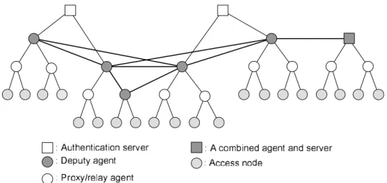
We designed a high-performance authentication architecture by extending the AAA scheme, basically supporting the integration of WLANs and cellular networks. The integrated net-work can also include other wireless technologies such as WiMAX and Bluetooth personal area network. Figure 1.1 illustrates a prototype of the architecture that represents the inte-grated network. The multiple agents that may be (extended) deputies are connected to each other in a peer-to-peer manner, while each controls a sub-tree in a hierarchical manner — the agents may reside on the same physical machine as the server. In this architecture, the authentication requests are processed in distributed agents. Given an authentication protocol that supports inter-domain authentication, collaborating agents enable authenti-cation efficiently by sharing security information. The security information is transferred among the agents; the peer-to-peer-based scheme does not reflect geographical topologies of end-systems. In consequence, an optimized structure, authentication protocol and
secu-Figure 1.1: An authentication scheme for the integrated networks. The authentication servers are responsible for a cellular network and/or WLAN. The deputy agents are con-nected to each other. The mobile users are associated with the access nodes. There possibly exist proxy and relay agents between the access nodes and servers.
rity information management characterize the architecture we designed.
1.6
Main Contributions
The following are the three main contributions made by this thesis:
• Decentralized Authentication Scheme: Conventional authentication schemes, based on a client-server model, are improved for cross-domain mobility. The current AAA protocols define several agents, including proxy and relay agents, but they do not enforce authentication and authorization. Authentication incurs a round trip time (RTT) due to transmission delays that are proportional to the distance between the server and clients. We define a deputy agent (referred to as an AAA broker in [43]) that performs an important role in the authentication process on behalf of the server; it differs from the server mostly in that the server has knowledge of the clients’ permanent information containing its secret key. Instead, the deputy agent is
1.6. Main Contributions 9 responsible for authenticating the MN using the security context pre-fetched from the server. The hierarchical authentication scheme with the deputy agents mitigates the authentication latency dramatically [23, 45].
• Mobility-adjusted Authentication Protocol (MAP): We propose a cross-domain authentication protocol [47]. It functions in two discrete ways. Initially, the mobile client and the server are mutually authenticated from scratch. This procedure results in producing a security context, including ID, pairs of temporary keys,
authentication codes and random numbers, validity, and other information. Next, MAP accomplishes minimum handshake in coordination with deputy agents, which contributes to a further reduction in the authentication latency. In contrast to
Kerberos [48] which favors inter-realm authentication, MAP achieves a significant reduction in the authentication latency without degrading high-level security. • Security Context Router (SCR): This efficiently manages the security context to
avoid remote contact with the home server, and is designed as an extension of the deputy agents. The key feature of the SCR is to provide predictive forwarding of the security context, characterized by approximate pattern matching and statistical estimation methods. The main contribution is a combination of effective algorithmic techniques for the acceleration of the handoff procedure, efficient estimation and security context transfer between the pairs of collaborating SCRs, which keep storage overhead to a minimum. Via experiments on a prototype implementation and numerical analysis, we demonstrate the performance benefits of the SCR using two methods and determine how well they lower storage overhead.
1.7
Thesis Outline
The remainder of this thesis is organized as follows.
Chapter 2 surveys the state of the art for WLAN and cellular network technologies and their authentication mechanisms, i.e. the IEEE 802.11i and (U)SIM. First, the IEEE 802.11i comprises the IEEE 802.1X that operates in coordination with the AAA and EAP-based protocols, the 4-way handshake and group-key handshake. Second, in addition to the authentication mechanisms, this chapter introduces the related work on fast authentication, including preauthentication and proactive caching of keys. Last, it describes authentication mechanisms (i.e. SIM and USIM) in the cellular network, and approaches to the integration of WLAN and cellular networks.
Chapter 3 concerns a hierarchical authentication scheme by introducing a deputy agent. First, it presents the effectiveness of the deputy agent via an experiment conducted with the implementation of an AAA-based UMTS application. The scheme is then generalized into a decentralized one that is represented as a mathematical abstract model. Lastly, this chap-ter quantifies the authentication latency based on the model, and evaluates the performance of the scheme.
Chapter 4 proposes a mobility-adjusted authentication protocol (MAP) for cross-domain mobility. MAP is characterized mainly by mutual authentication and pair-wise key gener-ation. It enhances the performance of the IEEE 802.11i authenticgener-ation. First, the chapter gives an overview of relevant systems i.e. the IEEE 802.11i mechanism, cross-domain-related protocols, and prerequisites of BAN logic. We then design MAP, including archi-tecture, defined keys and messages exchanged, and give a detailed description of elemen-tary modules. Afterwards, security concerns are discussed by first proving MAP in BAN logic and observing a variety of possible attacks. The performance of MAP is evaluated,
1.7. Thesis Outline 11 compared with the two protocols presented originally.
Chapter 5 concerns the design of a security context router (SCR). A group of SCRs form an overlay network and manage the security context. This chapter first describes the overall system on which the SCR is eventually built and then defines a mobility model that represents the movement direction of the MNs. We then design the SCR and elaborate on its two key features in predictive forwarding. In addition to these features, the functions of garbage collection and connectivity are described, and an analysis of lowering storage over-head is undertaken. The performance of the SCR is evaluated via simulation and numerical analysis.
Finally, Chapter 6 concludes this thesis with a discussion of possible future research directions, together with closing remarks.
Chapter 2
The State of the Art
In this chapter we present the security mechanisms defined and used in the main wireless technologies, i.e. WLAN and 3GPP, showing their algorithms and main characteristics. We also discuss their limitations in such circumstances as when the mobile node (MNs) intend to move across domains with no disruption of their ongoing sessions.
2.1
The IEEE 802.11i Standard
Security mechanisms for IEEE 802.11 networks were standardized in 2004, including a definition of wired equivalent privacy (WEP) for backward compatibility with the origi-nal IEEE 802.11 Standard, 1999. The IEEE 802.11i [12] is an amendment to the IEEE 802.11 standard specifying security mechanisms for wireless networks because WEP was shown to have severe security weaknesses. Its main goal is to provide robust security as-sociations for 802.11 networks. The IEEE 802.11i introduces the concept of a security association into wireless networks and defines security association management protocols. More specifically, the IEEE 802.11i architecture is composed of the IEEE 802.1X for
thentication; a robust secure network (RSN), containing the 4-way handshake, for security associations; and advanced encryption standard (AES)-based counter mode with a cipher block chaining-message authentication code protocol (CCMP) to provide confidentiality, integrity and authentication.
The IEEE 802.11i has three main components: mobile nodes (MNs), a set of access points along with authentication clients, and a back-end authentication server. When an MN finds an access point with the highest quality radio channels, a sequence of messages is exchanged: open authentication, IEEE 802.1X authentication, 4-way handshake and optional group-key handshake.
2.1.1
The IEEE 802.11 Association
Open system authentication exists for backward compatibility with WEP that is part of the IEEE 802.11 Standard ratified in 1999. It has a sequence of 2-message exchanges. The first message asserts identity and requests authentication, and the second message returns the authentication result. WEP uses the stream cipher Rivest Cipher 4 (RC4) for confidential-ity. The standard 64-bit WEP uses a 40-bit key to which a 24-bit initialization vector (IV) is concatenated to make the RC4 key. A 128-bit WEP key is constructed by combining a string of 26 Hexadecimal (Hex) characters, each of which represents 4 bits, with the 24-bit IV; i.e. 26 × 4 + 24 = 128-bit WEP key. However, there are weaknesses in WEP, including the possibility of IV collisions and alteration in packets. The same traffic key must never be used twice because RC4 is a stream cipher. Even if the purpose of an IV, which is trans-mitted as plaintext, is to prevent any repetition, a 24-bit IV is not long enough to avoid any collision. Borisov et al. [22] discovered several serious security flaws in WEP that result in practical attacks, showing that WEP fails to achieve its security goals. Cam-Winget et
2.1. The IEEE 802.11i Standard 15
al.[28] surveyed a variety of shortcomings in WEP, and Fluhrer et al. [9] presented several weaknesses in the key scheduling algorithm of RC4 and their cryptanalytic significance. After open system authentication, security parameters that specify encryption algorithms, security policy and other information are exchanged between the MN and access point via association exchanges.
2.1.2
The IEEE 802.1X
In the IEEE 802.1X system the MN and access points primarily correlate with each other; in particular, we refer to applications running on the MN and access points as supplicant and authenticator, respectively. The system is characterized by a port-based network access control. In an uncontrolled port (the authenticator is ‘switched off’) all traffic is unfiltered, while in a controlled port all traffic is blocked except for protocol data units (PDUs) related to extensible authentication protocol (EAP) [21]. When switched on, the authenticator either authenticates a device or user. In the case of mobile device authentication, it is identified by its media access control address (MAC address) that is pre-registered in the authenticator-associated database. In the case of mobile user authentication, the authenti-cator forwards EAP-based PDUs to a back-end authentication server for authentication. In the case of successful authentication, the port is opened, so that all PDUs are unblocked; otherwise, they remain blocked.
All three roles, i.e. a supplicant, authenticator and back-end authentication server, are necessary to complete an authentication exchange. A given system can adopt one or more of these roles; e.g. an authenticator and a back-end authentication server can be collo-cated within the same system, allowing that system to perform the authentication functions without the need for communication with an external server. However, the most common
implementation of this mechanism involves the use of an authentication server that is ex-ternal to the authenticators.
2.1.3
Authentication Authorization Accounting
The AAA Working Group in IETF [1] has developed requirements for Authentication, Authorization and Accounting as applied to network access, the definitions of which are as follows:
• Authentication refers to the confirmation that a user who is requesting services is a valid user of the network services requested. Authentication is accomplished via the presentation of an identity and credentials. Examples of types of credentials are passwords, one-time tokens, digital certificates and phone numbers (calling/called). • Authorization refers to the granting of specific types of service (including “no
service”) to a user, based on their authentication, what services they are requesting and the current system state. Authorization may be based on restrictions, e.g. time-of-day, physical location, or restrictions with respect to multiple logins by the same user. Authorization determines the nature of the service which is granted to a user. Examples of types of service include, but are not limited to: IP address filtering, address assignment, route assignment, QoS/differential services,
bandwidth control/traffic management, compulsory tunneling to a specific endpoint and encryption.
• Accounting refers to the tracking of the consumption of network resources by users. This information may be used for management, planning, billing or other purposes. Real-time accounting refers to accounting information that is delivered concurrently
2.1. The IEEE 802.11i Standard 17 with the consumption of the resources. Batch accounting refers to accounting information saved until it is delivered at a later time. Typical information gathered in accounting is the identity of the user, the nature of the service delivered, when the service began, and when it ended.
Since the AAA architecture is built based on a client-server model, the clients reside on the front-end authentication entity, such as access points or base stations, and send the authentication request. All authentication requests are processed in the AAA home server. The server is, in general, responsible for the authentication process from (part of) a domain and cooperates with the others to support cross-domain mobility. In addition to the client and server, relay, proxy, redirect and translation agents are introduced. Relay and proxy agents forward requests and responses based on routing-related attributes in the protocol and realm routing table entries. Relay agents do not make policy decisions and examine/alter any attributes in the packets to be forwarded, while proxy agents do. However, proxy agents do not respond to client requests prior to receiving a response from the server. In other words, it is possible for only the server to respond to the requests. Redirect agents refer clients to the server and allow them to communicate directly rather than forwarding requests and responses between clients and servers. Translation agents perform protocol translation among other AAA protocols. Consequently, when MNs are within a visited domain, the server in control of the visited domain forwards the requests to the MN’s home server. It is clear that the long-distance traffic of message exchanges occurs.
2.1.4
EAP-based Authentication Protocols
EAP [21] is a carrier protocol that carries any security protocols; e.g. transport level se-curity (TLS) [31] provides for mutual authentication and key exchange between two end-points and is carried over EAP-TLS [13]. In addition to EAP-TLS, there are a variety of EAP-based protocols, like EAP-SIM [36] for the SIM mechanism, EAP-AKA [18] for the zUSIM mechanism, protected extensible authentication protocol (PEAP) [67], EAP-SKE [72], EAP-TTLS [34], and so forth. These protocols must provide an authentication mechanism — most of which also support key generation after successful authentication. They operate, based on a client/server scheme. That is, an EAP peer runs on a supplicant and interacts with a back-end authentication server in the AAA scheme.
Figure 2.1 illustrates the relationship between the supplicant, authenticator and authen-tication server, as well as the structure of the protocols used. The authenticator’s controlled port is basically in the unauthorized state and therefore all PDUs are blocked. However, EAP payloads can pass through the authenticator; the communication between the au-thenticator and authentication server relies on either RADIUS [70] or Diameter [26]. The authentication server either authenticates the supplicant or there is mutual authentication between the authentication server and the supplicant, in both cases using one of the above EAP-based security protocols.
There are 4 types of packets in EAP: Request, Response, Success, and Failure. The authenticator sends the Request packet to the supplicant. Additional Request packets are always sent after a valid Response packet is received. The supplicant must send a Response packet in reply to a valid Request packet, but is not allowed to retransmit it during a given period of time. The Success or Failure packet is sent to the supplicant according to the authentication result. Figure 2.2 shows an EAP-based message exchange flow. After the
2.1. The IEEE 802.11i Standard 19
Figure 2.1: An example of relevant protocol stacks in the IEEE 802.1X. E-SP stands for EAP-based security protocols.
initial message initiated by the authenticator, the authentication server undertakes the rest of the exchange. The number of EAP message exchanges is subject to the EAP-based protocols used for either a mutual or unilateral authentication. Alternatively, a supplicant-initiated authentication is allowed; the supplicant sends the authenticator a trigger message, of EAPOL-Start. The subsequent exchanges are the same as the authenticator-initiated authentication.
2.1.5
4-Way Handshake
A successful authentication in the IEEE 802.1X leads to the generation of a pair-wise mas-ter key (PMK) shared between the supplicant and authentication server. The key is eventu-ally used for the 4-way handshake taking place between the supplicant and authenticator. The authenticator receives the PMK from the authentication server via a secure channel.
The IEEE 802.11 usesEAPOL-Keyframes to exchange information between the suppli-cants and authenticators. These exchanges yield cryptographic keys and a synchronization of security association state. The following is a description of each message exchanged in the 4-way handshake, ofEAPOL-Keyframes.
Figure 2.2: EAP message exchange
M1. is sent to the supplicant by the authenticator. It contains the key data field of an encapsulated the PMK identity (PMKID) and a random value that the authenticator generates. If this message is resent, the ID must be unchanged.
M2. is sent to the authenticator as a reply to M1. It contains the key data field of a robust security network (RSN) information element, a random value, and the message integrity code (MIC) of M2. The RSN information element contains authentication and pair-wise cipher suite selectors, a single group cipher suite selector, an RSN capabilities field, the PMKID count and PMKID list. All supplicants implementing RSN association support this element. The size of the RSN information element is limited by the size of an information element which is 255 octets. On receipt of M2, the authenticator verifies that the pair-wise cipher suite selected is one of its
configured cipher suites and that the group cipher suite is consistent.
2.1. The IEEE 802.11i Standard 21 element, a random value and an MIC. If a group cipher has been negotiated, it also includes an encapsulated group temporary key (GTK). The authenticator inserts the RSN information element it previously sent in the Beacon/Probe response message. The supplicant verifies the selected security RSN information with the RSN
information element in M3. If the values do not match, the supplicant breaks the association by invoking aDeauthenticaterequest. A security error is logged at this time.
M4. is sent to the authenticator. It contains the key data field that can be empty or can contain an MIC.
During the 4-way handshake, both the supplicant and authenticator generate a PTK. Figure 2.3 shows an example of the 4-way handshake message exchanges.
• The authenticator sends anEAPOL-Keyframe containing an ARAND. The supplicant derives a PTK from the ARAND and SRAND. That is, it computes PRF-X(PMK, “pairwise key expansion” | Min(AA,SPA) | Max(AA,SPA) | Min(ARAND, SRAND) | Max(ARAND, SRAND)), where PRF-X is a pseudo random function generating X-bit output data, and AA and SPA denote the MAC addresses of the authenticator and supplicant, respectively. Note that the PMK is known only by the supplicant and authenticator.
• The supplicant sends anEAPOL-Keyframe containing the SRAND, the RSN information element from the (re)association request frame, and an MIC. The authenticator derives a PTK from the ARAND and SRAND in the same manner as the supplicant, and verifies the MIC in theEAPOL-Keyframe.
Figure 2.3: An example of the 4-way handshake
information element from its Beacon/Probe response messages, MIC and the encapsulated GTK (if available).
• The supplicant sends anEAPOL-Keyframe to confirm that the temporary keys are installed.
The authentication server also knows the PMK. Therefore, additional assumptions are required: the authentication server does not expose the PMK to other parties, it does not masquerade as the supplicant to the authenticator or as the authenticator to the supplicant, and it does not masquerade as the supplicant itself or the authenticator. If any of these assumptions are broken, then the protocol fails to provide any security guarantees.
The 4-way handshake uses random values against replay. The ARAND provides replay protection to the authenticator, and the SRAND to the supplicant. In most session initiation protocols, replay protection is explicitly accomplished by selecting a random value and requiring the peer to reflect the received random value in a response message. The 4-way
2.1. The IEEE 802.11i Standard 23 handshake instead mixes the ARAND and SRAND into the PTK, and replays are detected implicitly by MIC failures.
2.1.6
Group-key Handshake
The authenticator uses the group-key handshake, which is optional, to send a new GTK to the supplicants. The following are the message exchanges:
M1. authenticator → supplicant:EAPOL-Key(RSC, MIC, GTK[KeyID])
The authenticator generates, encapsulates and sends a new GTK, along with the last sequence number (receive sequence counter (RSC)). The supplicant verifies the MIC, decapsulates the GTK with KeyID obtained during the 4-way handshake, and configures it.
M2. supplicant → authenticator:EAPOL-Key(MIC)
The authenticator verifies the MIC and configures the GTK into the IEEE 802.11 MAC if verification is successful.
If the authenticator does not receive a reply to its messages during a given period of time, it deauthenticates the supplicant, and the supplicant fails to be authenticated.
2.1.7
Fast Authentication
Preauthentication
Preauthentication as part of the IEEE 802.11i can be useful for a performance enhancement of handoffs. Figure 2.4 depicts a sequence of a preauthentication process. Before preau-thentication, the new AP, with which the MN will be associated, advertises the preauthen-tication capability in the RSN information element. An MN’s supplicant initiates
preau-Figure 2.4: An example of preauthentication. Current and target APs (i.e. cAP and tAP) are in the boundary of an authentication system. Steps 1 and 2 are assumed to be completed before preauthentication starts.
thentication after completing the 4-way handshake and configuring the required temporary keys. It sends the authenticator of the target AP the IEEE 802.1X EAPOL-Start message with the addresses of the APs. The IEEE 802.1X authentication takes place and a success-ful authentication results in deploying a PMK security association (PMKSA) to the MN and preauthenticated AP. Then, when the MN associates with the preauthenticated AP, the supplicant uses the PMKSA to perform the 4-way handshake. Unless the PMKSAs of the supplicant and authenticator are matched, the 4-way handshake fails and the IEEE 802.1X authentication is performed from scratch. The main drawback of preauthentication is that it is highly uncertain that the MN will be associated with the preauthenticated AP.
Proactive Caching of Keys
One can achieve fast authentication with proactive key distribution [58]. Figure 2.5 depicts how the AS propagates PMKSAs to relevant APs with which the MN may be associated. The AS builds neighbor graphs that represent associations among APs [57]. After the MN completes the 4-way handshake, the AS propagates PMKSAs to the selected APs, refer-ring to a neighbor graph — there is a variant, i.e. a selective neighbor caching scheme [66]
2.2. Authentication in 3GPP 25
Figure 2.5: Proactive key distribution. cAP is an AP with which the MN is currently associated. The AS propagates the derived PMKs to APs selected based on a neighbor graph (NG).
that propagates a subset of neighbor APs, distinguishing the probability of each AP with which the MN will be associated. Each PMKSA is computed by hashing a combination of MK, the old PMKSA, and the addresses of the MN and each AP, i.e. PMKSAn=H(MK,
PMKSAn−1, MN’s MAC Address, AP’s MAC Address). When the MN is associated with one of the APs that has PMKSA pre-deployed, the MN and AP perform the 4-way hand-shake directly without the IEEE 802.1X. If their PMKSA is different, the IEEE 802.1X runs from scratch. The neighbor graphs can also be managed in each AP. If so, then PMKSA is propagated via IAPP [11].
2.2
Authentication in 3GPP
The authentication mechanisms in the 3G partnership project (3GPP) [10] are divided into UMTS authentication and GSM authentication. UMTS authentication is based on a USIM for authenticating the MN and network (e.g. authentication server (AuC)) — it implies mutual authentication in contrast to GSM authentication, while GSM authentication is based on a SIM or GSM-capable USIM for authenticating the MN. GSM authentication
uses a triplet of parameters: a network challenge (RAND), an expected response value (SRES), and cipher key (Kc); UMTS authentication uses a quintet of parameters: RAND, an expected response (XRES), cipher key (CK), integrity key (IK) and authentication token (AUTN).
The GSM network authenticates the international mobile subscriber identity (IMSI) through the use of a challenge-response mechanism. A 128-bit RAND is sent to the MN. The MN computes the 32-bit SRES based on the encryption of the RAND with the au-thentication algorithm (A3) using the personal identity number (PIN). Upon receiving the SRES, the GSM network repeats the calculation. If the received SRES and the calculated value match, the MN is successfully authenticated. Otherwise, the connection is terminated due to an authentication failure. Similarly, the UMTS network uses a challenge-response mechanism. In contrast, it sends a challenge message additionally containing the AUTN. Upon receiving this message, the USIM in the MN verifies the AUTN, and if it is accepted, the USIM continues to compute the signature of RAND and RES, and then sends RES to the UMTS network while computing a new CK and IK. The UMTS network compares the received RES and XRES. If they match, a mutual authentication is successfully achieved and both the UMTS network and MN eventually generate the Kc from the CK and IK.
2.3
The Integration of WLAN and GPRS
WLAN can complement mobile operators’ traditional wide-area General Packet Radio Ser-vice (GPRS) by offering a cost-effective wireless broadband data solution indoors. Several approaches have been proposed for interworking between WLANs and cellular networks. The European Telecommunications Standards Institute (ETSI) has specified two generic approaches i.e. tight coupling and loose coupling [33]. With tight coupling, the WLAN is
2.3. The Integration of WLAN and GPRS 27 connected to the GPRS core network via serving GPRS support node (SGSN) and treated as other radio access networks (RANs), such as GPRS RAN and UMTS terrestrial RAN. Therefore, the WLAN data traffic flows through the GPRS network before reaching IP-based networks. This scheme is primarily tailored to support WLANs operated by cellular operators, and thus hardly supports third-party WLANs. On the other hand, with loose coupling, the WLAN reaches IP networks via an operator’s IP network, and is thus con-nected to the GPRS network via the gateway GPRS support node. The solution to this scheme relies substantially on IETF protocols; i.e. Ala-Laurila et al. [17] presented a new WLAN system architecture that combines WLAN technology with mobile operators’ SIM-based subscriber management functions and roaming infrastructure. Salkintzis et al. [73] compared the two internetworking mechanisms and discussed their advantages and draw-backs. In particular, an authentication system in an integrated network with loose coupling is based on AAA protocols, such as RADIUS and Diameter.
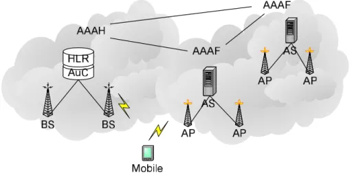
Figure 2.6 depicts an integrated authentication system via the AAA architecture that covers WLANs and cellular networks. If the MN subscribes to a cellular operator, then the AAA associated with the cellular network becomes its home server (AAAH). When the MN intends to have access to a WLAN, the authentication request is forwarded to AAAH; AAAF plays a role of proxy/relay agent in this case.
Figure 2.7 shows a signaling diagram for a successful SIM-based authentication while the MN roams in a WLAN. At first, the MN’s supplicant sends an authentication triggering message,EAPOL-start, to an AP’s authenticator (e.g. RADIUS client). In messages 2 to 4, the authenticator obtains the MN’s ID — which corresponds to IMSI in the case of GSM and UMTS — and forwards the ID to its back-end authentication server (e.g. RADIUS server). The server notices that the MN belongs to another server in a foreign domain by verifying a domain indicator that is usually set by the supplicant. The RADIUS client can
Figure 2.6: An integrated authentication system covering WLANs and cellular networks also attach the domain indicator to which this request will be forwarded, and to do so, pre-configuration in the client is required. When receiving message 5, the MN’s home server (e.g. RADIUS server) fetches authentication information, i.e. GSM authentication vectors (UMTS authentication vectors for UMTS) by sending the MN’s IMSI (in messages 6 and 7). In messages 8 and 9, the home server sends a random-challenge message, forwarded by the foreign server, to the authenticator. In messages 10 and 11, the MN’s supplicant computes an SRES with the received RAND and sends the authenticator the SRES. In messages 12 and 13, the home server matches the SRES received via the foreign server with the XRES. The authentication result is transferred to the MN eventually in messages 14 to 16 (it is a successful authentication in the figure; otherwise RADIUS access-reject
and EAP-failure are sent). Afterwards, the 4-way handshake or WEP security can be performed depending on what security mechanism is used to protect the WLAN. Each time the MN roams around in a foreign domain, the above steps are repeated. Therefore, in terms of the performance issue, such authentication mechanisms must be improved.
2.3. The Integration of WLAN and GPRS 29
Figure 2.7: An example of successful SIM-based authentication with the MN roaming in a WLAN foreign domain. AAAF and AAAH are RADIUS servers in the WLAN and GPRS, respectively. CAG stands for cellular access gateway that is an interface between IP-based network and GPRS. HLR manages subscribers’ credentials.
Chapter 3
Decentralized Authentication
Architecture
3.1
Introduction
The server in the AAA scheme verifies the MNs’ ID, authorizes them to use resources and enforces a security policy on their profile. The server is passive: it waits for requests and sends a reply. The clients, on the other hand, send requests and wait until replies arrive. Such a scheme fundamentally suffers from authentication failures caused by authentica-tion request congesauthentica-tion regardless of MNs’ legitimacy, and incurs significant latency in authentication with the MNs roaming in a visited domain.
Since the proxy and relay agents defined in the AAA framework are not allowed to en-force the authentication policy, we introduce a deputy agent that authenticates the MNs on behalf of the server. After successful authentication, the server generates and transfers secu-rity information to a deputy agent, so that the deputy agent can process consecutive requests while the MNs are roaming. First, we present an implementation of an AAA-combined
UMTS network authentication via which we demonstrate the impact of the deputy agent on authentication latency. The application of the AAA-combined UMTS network authenti-cation (called AAA-UMTS appliauthenti-cation) generates a set of authentiauthenti-cation elements that are included in security information. In addition to the application, we build an abstract model that represents a decentralized scheme that consists mainly of multiple deputy agents, and quantify the authentication latency in message signaling. The evaluation analysis results in determining which deputy agent best handles the authentication process.
The remainder of this chapter is organized as follows. Section 3.2 presents the imple-mentation of the AAA-UMTS application, including command codes and defined attribute values, and describes a UMTS authentication procedure. It then evaluates the performance results of the experiment conducted, with the implementation in a UMTS platform. Sec-tion 3.3 details a decentralized authenticaSec-tion scheme with multiple distributed deputy agents, defines an abstract model of the scheme, and quantifies authentication latency in terms of message exchange cost. Section 3.4 evaluates the performance of the model and Section 3.6 concludes this chapter.
3.2
AAA-UMTS Application
Command Codes
We use the same AA-Request (AAR) and AA-Answer (AAA) messages that are defined in the Diameter network access server application [27]. The messages are captured to apply the UMTS authentication mechanism according to the presence of the attribute value of
3.2. AAA-UMTS Application 33 Defined Attribute Values
• Challenge-Requestis of type Enumerated and contains the request-type identifier determining if it is for a request or response.
• UMTS-Proxy-Capabilityis of type OctetString and contains one octet
identifying that there exists a deputy agent capable of serving, as an auxiliary AAA server as described above.
• UMTS-Vectoris of type Grouped and containsUser-Name,RENDandXRES. It may appear in the response to challenge. If no deputy agent is able to handle the attribute value (AV) pair, the onlyRENDis sent to ordinary proxy agents. Its data field has the following ABNF grammar:
UMTS-Vector ::= < AV header > { User-Name } { REND } { XRES } *[ AVs ]
• User-Nameis of type UTF8String and contains an ID.RENDis of type OctetString and contains 16 octets with the ‘P’ protection bit enabled. XRESis of type
OctetString and contains 16 octets with the ‘P’ bit enabled.
• Token-Responseis of type OctetString and contains 16 octets with the ‘P’ bit enabled. It is computed and sent to the deputy agent.
UMTS Network Authentication
Provided that the MN visits the UMTS domain, it requests authentication by sending its ID. The AAA client captures this message.
M1. Client → Server: AAR (User-Name,Challenge-Request,
UMTS-Proxy-Capability)
On capturing the request, the AAA client sends an AAR message to the home server via several deputy agents containing theChallenge-RequestAV, indicating that a challenge token is required. Any one of the deputy agents may add the
UMTS-Proxy-CapabilityAV to the message, which signifies that it joins the authentication mechanism.
M2. Server → Deputy: AAA (User-Name,UMTS-Vectors)
The server verifies the presence of theUMTS-Proxy-CapabilityAV in the message, and if several AVs are found, the server chooses an appropriate agent to handle the request via analysis that will be detailed in Section 3.3. In the
experimentation version used for evaluation, however, the one in the domain in which the request was originally issued is chosen. The server generates a random value (REND) and computes expected response (XRES) by applying HMAC algorithms [50] with the REND and an MN-shared key. It sends the AAA message, including User’s ID and multipleUMTS-Vectors ofRENDandXRESAVs. In case of noUMTS-Proxy-CapabilityAV found in the AAR message, only aRENDAV is included in the message.
M3. Deputy → Client: AAA (User-Name,REND)
The chosen deputy agent extracts the REND from the AAA message and then sends it to the MN to be challenged.
3.2. AAA-UMTS Application 35 M4. Client → Deputy: AAR (User-Name,Challenge-Request,Token-Response)
The MN computes an RES with the shared key and the received REND, and responds with the AAR message, including theToken-ResponseAV containing the computed RES and theChallenge-RequestAV set to a value signifying response.
M5. Deputy → Client: AAA (User-Name,Response)
The deputy agent verifies if the received RES is matched with the corresponding XRES, and then replies with a success/reject message. The next request is treated in the deputy agent without contacting the server.
3.2.1
Evaluation of the AAA-UMTS Application
Figure 3.1 illustrates a scenario of the AAA-UMTS application during inter-domain hand-offs. We implemented the application based on the Diameter NASREQ application [27], including proxy, relay and deputy agents. A Diameter client is installed in the base sta-tion, and the deputy agent serves as a Diameter server in the Sophia domain. The MN registers with a Diameter server in the Star-vthd domain. An alternate Diameter server in the Enst domain is necessary for evaluation. When associated with the base station, the MN issues the request via an ad hoc protocol, typing user ID and password. The Diameter client sends a Diameter-transformed request to the home server in the Star-vthd domain. For experimentation purposes, it can forward the request to the proxy agent in the Enst domain. The Diameter server in the Star-vthd domain responds with AV pairs to the deputy agent, and then the deputy agent can enforce the UMTS authentication policy. Therefore, the long-distance traffic of message exchanges is substantially reduced.
Figure 3.1: Inter-domain authentication via Diameter over UMTS. RTTs between the deputy agent and Diameter server, and between the server and an alternate server corre-spond to 9.97ms and 1.23ms, respectively. All associations between the client and deputy, the server and deputy, and the server and the alternate server are assumed to be secure.
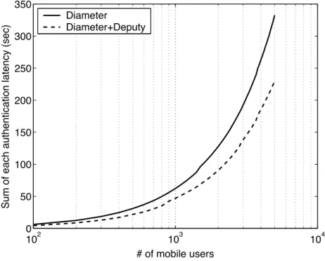
3.2. AAA-UMTS Application 37 102 103 104 0 50 100 150 200 250 300 350 # of mobile users Su m o f e a ch a u th e n ti ca ti o n l a te n cy (se c) Diameter Diameter+Deputy
Figure 3.2: Comparison of authentication latency between Diameter and the combination of Diameter and deputy agent as the number of MNs increases. The latency from sending a request to receiving its result is measured.
latency. Authentication in the original Diameter application is processed solely on the server in the Star-vthd domain, while the deputy agent in the Sophia domain authenticates the MN after receiving security information. About 29% of reduction in the authentication latency is achieved in this experiment. The latency gain increases as the MN moves away from the home server.
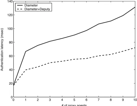
We install multiple proxy agents in the servers in the Enst and Star-vthd domains, and switch their role from server to proxy, alternately, which emulates the increase in their distance. For example, if 2 proxy agents are necessary, the Diameter server in the Star-vthd domain forwards the request to the server in the Enst domain as a proxy and then processes the returned request as a home server. Figure 3.3 shows the increase in authenti-cation latency as the distance grows. As expected, the latency gain increases proportionally,
0 1 2 3 4 5 6 7 8 9 10 0 20 40 60 80 100 120 140 # of proxy agents Au th e n ti ca ti o n l a te n cy (mse c) Diameter Diameter+Deputy
Figure 3.3: Increase in authentication latency as the distance grows
e.g. with 4 proxy agents traversed during the authentication process, 40% latency gain is achieved, and it increases up to 45% with 10 proxy agents.
3.3
Decentralized Authentication Scheme
In an attempt to secure no false negative failures of authentication by the server and the fast cross-domain handoff process, in this section, we introduce an abstract model of the decentralized authentication scheme consisting of multiple deputy agents, and quantify the authentication latency.
3.3. Decentralized Authentication Scheme 39
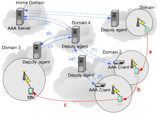
Figure 3.4: Mobile authentication scenario; the connections between deputy agents, be-tween AAA clients and agents/servers, bebe-tween agents and server are assumed to be secure.
3.3.1
Mobile Authentication
Figure 3.4 illustrates the message flow of authentication during the cross-domain handoff. After crossing the domain boundary, the MN associates with an access point in domain 2, and the request is sent to the home server via two deputy agents adding the joining attribute (e.g. UMTS-Proxy-Capabilityin the AAA-UMTS application). The server determines which deputy agent will undertake the mobile authentication, taking the latency factors into consideration based on an abstract model, which is detailed shortly. Provided that the deputy agent in domain 4 is chosen, the consecutive requests are processed in that agent regardless of the MN handing off into domain 3.
3.3.2
An Abstract Model
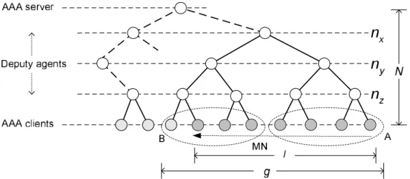
Figure 3.5 illustrates a binary-tree-based abstract model. The root and leaves in the binary tree correspond to the AAA server and clients, respectively. An intermediate node is one of deputy, proxy, and relay agents. We assume that all intermediate nodes can play a deputy role in the mobile authentication. We also assume that costs of exchanging a message between all adjacent nodes is the same (i.e. 1 for simplicity); e.g. the cost of sending and receiving back a message to a 2-hop-distance node is equal to 2. The goal in this model is to choose a deputy agent that allows one to keep the cost to a minimum; e.g. if the MN moves around in group A, then ny may be optimal, and if it moves across groups A and B,
then nx may be optimal.
Figure 3.5: An abstract model for quantifying cost of message exchanges. Parameters l and grepresent the number of access points that the MN traversed and the number of groups that it visited, respectively. N denotes an end-to-end cost and nx, ny, and nz denote the
respective heights of the tree corresponding to the deputy agents’ positions.
Cost Function: The following is the derivation of a minimal cost function. When the MN is initially authenticated, the authentication request is sent to the server, which costs N. After a successful authentication, the server calculates a deputy’s position that will be
3.3. Decentralized Authentication Scheme 41 somewhere in the middle. Each time the MN moves with l − 1 associations (it counts once with a new access point), the request is processed in a chosen deputy agent. Then, the cost with respect to l is
(l − 1)log l
log 2 + N. (3.1) If no deputy agent is determined, then the cost is
N × l, (3.2)
which corresponds to a non-optimized authentication scheme as well. We divide l into g groups, i.e. l = l1+ l2+ ... + lg, assuming that a deputy agent controls each group of clients.
The sum of costs with respect to each group is (l1− 1)
log l1
log 2 + ... + (lg− 1) log lg
log 2 + gN. (3.3) Here, we define a convex function for an interval [1, b],
f(x) = g(x − 1)log x
log 2, . (3.4) Then, Eq. (3.3) is expressed as
1
For any two points x1and x2in that interval, f (x) holds 1/2( f (x1) + f (x2)) ≥ f ((x1+ x2)/2). Therefore, we obtain 1 g( f (l1) + f (l2) + ... + f (lg)) + gN ≥ f ( 1 g × (l1+ l2+ ... + lg)) + gN = f (gl) + gN, (3.6) which is a lower bound of the cost function when l1 = l2 = ... = lg = l/g. Therefore, the
cost function with respect to g is
fC(g) = (l − g)
loggl
log 2 + gN. (3.7) In particular, when g = 1, fC results in Eq. (3.1), and when g = l, it results in Eq. (3.2).
Therefore, reducing the cost of authentication requests allows one to adjust g, which in turn produces an optimal deputy’s position.
Approximation to Optimal g: We here attempt to compute g that results in minimizing fC. The derivative of Eq. (3.7) with respect to g is
fC′(g) = N + − log( l g) + 1 − l g log 2 (3.8)
and the second derivative is
fC′′(g) = 1 g+ l g2 log 2 , (3.9) which is strictly positive. Thus, f′
C is an increasing function, and there are two cases when
g = 1 as the basis. (1) If fC′(1) ≥ 0, then we deduce that for any g > 1, fC′(g) > 0 because
fC′(g) is the increasing function. That is, when g = 1, fC(g) is minimal — it is true only if
3.4. Performance Evaluation 43 f′ C(g) = 0 which implies Nlog 2 = log(l g) + l g − 1. (3.10) Considering that log(l/g) ≪ l/g, Eq. (3.10) approximates to l/g ≈ 1 + N log 2. Therefore, gapproximating to gopt is gapprox ≈ l
1+N log 2 for N log 2 + 1 < l + log l,
1 for N log 2 + 1 ≥ l + log l.
(3.11) Latency Gain: The following is a numerical gain in latency from a non-optimized authentication scheme.
fC(l) − fC(g) = (l − g)(N −
loggl
log 2). (3.12) For N log 2 + 1 < l + log l, the gain is
(l − l
1 + N log 2)(N −
log(1 + N log 2) log 2 ) ≈
l(N log 2 − log(N log 2))
log 2 (3.13) and for N log 2 + 1 ≥ l + log l, it is
(l − 1)(N − log 2log l) ≈ (l − 1)N. (3.14) In both cases the gain increases as l → ∞ or N → ∞.
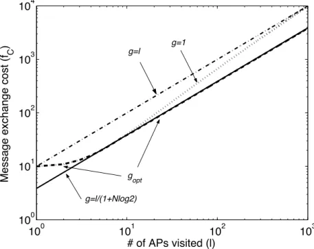
3.4
Performance Evaluation
A Good Approximation of g: Figure 3.6 shows the performance result from comparing the authentication cost with various values of g. The optimal g generates the best performance