Efficient Model Selection for Real-Time
Adaptive Cold Start Strategy of a Fuel Cell
System on Vehicular Applications
A. Amamou
1,2,3, M. Kandidayeni
1,2,4, A. Macias
1,2,5, L. Boulon
1,2,6, S. Kelouwani
1,2,7 1Institut de Recherche sur l’Hydrogène, UQTR, Trois-Rivières, QC G9A 5H7, Canada
2
Université du Québec à Trois-Rivières, 3351 Boulevard des Forges,
Trois-Rivières, QC G9A 5H7, Canada
3[email protected] 4[email protected] 5[email protected]
6[email protected] 7[email protected]
Abstract— The PEMFC maximum power is greatly influenced by subfreezing temperature and degradation phenomena. Therefore, a dependable model is required to estimate the power with respect to the variation of the operating conditions and state of health. Semi-empirical models are potent tools in this regard. Nonetheless, there is not much information about their cold environment reliability. This paper comprehensively compares the performance of some models (already tested in normal ambient temperature) in subfreezing condition to introduce the most reliable one for PEMFC cold start-up application. Firstly, seven models are compared regarding voltage losses and precision. Subsequently, the three most dependable ones are selected and experimentally compared at sub-zero temperature in terms of polarization curve estimation for three PEMFCs with different degradation levels. The results of this study indicate that the model introduced by Amphlett et. al has a superior performance compared to other ones regarding the characteristic’s estimation in below-zero temperature.
Index Terms—Cold start, experimental approach, online identification, proton exchange membrane fuel cell, semi-empirical model.
1 INTRODUCTION
Nowadays, environmental and economic issues have triggered a rising tendency in the emergence of electrified vehicles as a substitute for conventional ones. Fuel cell-hybrid electric vehicle (FC-HEV) is a kind of HEV in which the principal power source is a FC stack and the secondary power source is an energy storage device, such as battery and/or a supercapacitor, to power an electric motor [1]. Compared to traditional HEVs, a FCHEV is more beneficial in terms of emission and efficiency, and compared to pure battery vehicle, it has less recharging time and more autonomy. However, owing to some limitations, such as constricted hydrogen infrastructure and accessibility, high cost, and imperfect extreme cold weather performance, FCHEVs have not yet achieved the anticipated market penetration [2]. The main focus of interest in this manuscript is the renowned cold start problem of FCs which is an important issue in cold weather countries. Several studies have been carried out regarding the freezing mechanisms in proton exchange membrane (PEM) FCs, which are perceived as one of the most prospective nominees in vehicular application [3]. In sub-zero conditions, the generated water mainly in the cathode side ices over and blocks the reaction sites which in turn leads to the performance plunge, accelerated degradation, and cold start-up failure [4-8]. In this respect, in-depth analyses of cold start aspects and the development of related strategies are of great significant. In fact, the cold start strategy is a matter of interaction between water and heat
POSTPRINT VERSION. The final version is published here: Amamou, A., Kandidayeni, M., Macias, A., Boulon, L., & Kelouwani, S. (2020). Efficient model selection for real-time adaptive cold start strategy of a fuel cell system on vehicular applications. International Journal of Hydrogen Energy. http://dx.doi.org/https://doi.org/10.1016/j.ijhydene.2020.04.253 CC BY-NC-ND
2
management [9]. Improper water removal and inadequate heat generation for warming up the cell over the freezing point result in the ice formation in the cathode catalyst and gas transfer channels and cause the previously mentioned problems [10]. The existing strategies regarding the PEMFC cold start-up procedure can be split into two categories of Keep Warm and Thaw at Start where the former is mainly based on the use of block heaters or other methods to keep the PEMFC temperature around its minimum operating temperature during the parking [11-14]. According to [3], the Thaw at Start based strategiesare more suitable for vehicular applications, since the parking duration is unforeseeable, and are grouped into two categories of assisted and self-cold start strategies. Assisted cold start strategies utilize an exterior source of heating which is practical for declining the start-up time, nevertheless it increases the bulk, weight, price and energy productivity of the PEMFC system [15-18]. Self-cold start strategies normally generate heat by the exothermic reaction, internal reaction independent of an external source, through some methods such as fixing the current density (galvanostatic) [19-21] or cell voltage (potentiostatic) [22-25], and the maximum power mode [26, 27]. Moreover, these strategies have a purging mechanism after shut-down to avoid water retention and thus ice formation in the cathode catalyst layer. Galvanostatic and Potentiostatic start-up methods have been mentioned as being very efficient in terms of energy requirement and system cost in many researches [3]. Guo et al. [21] proposed the use of O2/H2 mixture on the anode side to rise the heat flux from the galvanostatic strategy with the purpose of performing a self-cold start from -20 °C. This strategy, though successful, needs a modification of the PEMFC system, and its performance highly relies on the PEMFC states (temperature, membrane hydration, degradation etc.).In [22-24], cold start strategies based on purging the PEMFC before shut-down and applying constant voltage mode to rise the temperature in start-up are proposed. These strategies are proven to be functional at cold start from -20 °C, however, their performance depends on the state of the PEMFC. In [26], a PEMFC cold start strategy is proposed premised on the maximum power mode of the stack, and compared with both galvanostatic and potentiostatic methods. The results of this paper show that the maximum power cold start mode is capable of balancing the heat production and the ice formation, resulting in an enhanced cold start survivability compared to the well-known constant voltage and constant current modes. One common problem of all the three galvanostatic, potentiostatic, and maximum power mode cold start strategies is that their operation is afflicted to a great extent by the PEMFC system performance drifts owing to the variation of degradation state and operating conditions [28]. Performance degradation of PEMFCs is usually defined by the loss of voltage versus time [29, 30]. Degradation of PEMFC components results in an overall drop in PEMFC performance, which negatively affect the cold start performance of the internal heating solutions (galvanostatic, potentiostatic, and maximum power mode). In addition, subfreezing temperature causes also power and voltage losses versus PEMFC current, which affects considerably the robustness of the proposed internal heating solutions. Therefore, there is a need for an accurate online model to estimate the PEMFC characteristic’s curve with respect to the alteration of the operating conditions as well as the PEMFC state of health [31, 32]. In [27], an adaptive cold start strategy is proposed based on maximum power mode of the PEMFC stack as well as the purging procedure before shutting down to update the strategy according to the performance drifts. This work demonstrates satisfactory results by estimating the PEMFC maximum power with a single-input semi-empirical model based on the operating current. The parameters of the model are updated in real-time by means of recursive least square filter. However, a wise selection of the PEMFC model is still required since the proposed cold start-up approach is based on maximum power estimation. Inappropriate selection of a semi-empirical model can lead to the imprecise prediction of the PEMFC maximum power which in turn challenges the operation of the cold start strategy based on maximum power mode. Several semi-empirical models are available in the literature to predict the behavior of a PEMFC stack [33-39]. Nonetheless, all of these models have been tested in above-zero operating temperatures.
The main contribution of this paper lies in the performance analysis of the semi-empirical models in subfreezing conditions with a view to be used in the development of an adaptive maximum power mode based cold start strategy for a PEMFC stack. In this regard, firstly, a review of seven semi-empirical models is performed in terms of granularity and the characteristics considerations. Afterwards, three models, suggested by Squadrito et al. [38], Amphlett et al. [35], and Boulon et al. [39, 40], are selected for further experimental investigations in below-zero temperature condition. In order to counteract the influence of the
3
operating conditions variation and degradation phenomenon, the parameters of the models are estimated online by means of recursive maximum likelihood (RML) algorithm.
Section 2 highlights the necessity of maximum power point estimation in the PEMFC cold start-up procedure. Section 3 deals with the explanation and selection of the three above-mentioned semi-empirical models. The RML filter and its customization for the online parameter estimation of this work are explained in section 4. Section 5 describes the experimental procedure used in this work along with the detailed discussion of the experimental results regarding the comparison of the models. Finally, the conclusion is given in Section 6 with some future perspectives regarding this problem.
2 MAXIMUM POWER POINT ESTIMATION NECESSITY IN THE PEMFC COLD START-UP
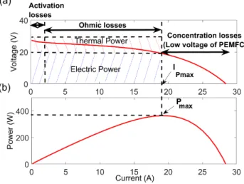
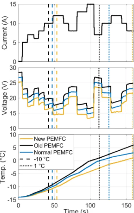
The existing manuscripts in the literature confirm the possibility of performing the PEMFC cold start without using external heating-based methods and devices [22-24, 26, 41]. However, in order to avoid cold start failure, the choice of the operating point during autonomous PEMFC cold start is crucial. It is important to note that high-current operation increases the PEMFC thermal power as well as the cold start capability. However, running the PEMFC at high current also reduces the oxygen (O2) and hydrogen (H2) concentration which naturally causes a pressure drop inside the PEMFC [10]. This pressure drop leads to a sharp voltage drop commonly known as concentration loss. The point to be underlined is that concentration loss becomes significant at high current levels where it can degrade the PEMFC stack and fail the cold start procedure [42, 43]. Therefore, it is vital to find the operating point that maximizes the heat generation while avoiding cold start failure. Based on literature [3] and the presented PEMFC characteristics in Fig. 1, it can be said that PEMFC system has a current or voltage threshold corresponding to the maximum power. Exceeding this limit results in an increase in concentration loss and PEMFC degradation [3]. In this regard, it is suggested to operate the PEMFC at its maximum power (Pmax) during cold start. This operation mode maximizes produced heat inside the PEMFC and avoids operating the PEMFC at low voltages (Fig. 1). In addition, it maximizes electrical power during the cold up. The application of the maximum power mode cold start-up strategy has been successfully tested in closed cathode and open cathode PEMFCs [27, 44]. However, a major limitation of all internal heating solutions include maximum power mode is the lack of information about the formed ice during the phase change which can block the reaction sites, reduce the performance, accelerate the degradation and lead to the failure of cold start. Therefore, it is crucial to consider a water evacuation process after each PEMFC shut down to keep the ice formation to minimum level. It is also important to develop a real-time diagnostic algorithm to realize the ice formation inside the stack. If cathode catalyst layer is fully blocked by ice, all the internal heating solutions are inefficient, and an external material heating system remains necessary.
4
The PEMFC maximum power can be identified from the power curve. Nevertheless, this maximum power is not fixed during the lifetime of the PEMFC stack. In fact, the alteration of the operating conditions and degradation level of the stack has a significant impact on the maximum power point [45, 46]. During the PEMFC cold start, the formed ice inside the PEMFC increases concentration loss which in turn affects the power curve. Moreover, the generated heat during the start-up decreases the ohmic loss, which also influence the power curve [47]. As a result, the PEMFC maximum power changes significantly during the cold start and it is essential to identify it online.
3 PEMFC SEMI-EMPIRICAL MODELING
Mathematical modeling assumes a leading role in the technological evolution of a PEMFC system [48]. Depending on the purpose of a study, a suitable PEMFC model in terms of granularity and computational time should be selected. The existing PEMFC models in the literature can be grouped into three distinct categories of mechanistic, empirical, and black box. According to a conducted study in [49], semi-empirical models are very suitable for estimating the characteristics of a PEMFC system, such as polarization and power curves, and their operating range can be extended when combined by recursive filters. These models are premised upon the physical relationships which are supported by experimental data and demonstrate the fundamental electrochemical aspects of the PEMFCs [50, 51]. Furthermore, working with a semi-empirical model makes it possible to evaluate the relevance of the results due to the physical meaning of the parameters. However, not much information is available in the literature regarding the dependability analysis of semi-empirical models in subfreezing conditions, which is the main target of this paper. Several semi-empirical models have been introduced for imitating the behavior of a PEMFC. This section lays emphasis on the ones which are suitable for real-time application (a trade-off between accuracy and operation time) since the application of this work will be the design of adaptive power mode based cold start strategies. In this regard, a comparative study of seven well-known semi-empirical models, as listed in Table I, is performed. The selected models are referred to by the name of the author. These models represent the electrochemical behavior of a PEMFC based on its polarization curve, as shown in Fig. 1, with different levels of precision.
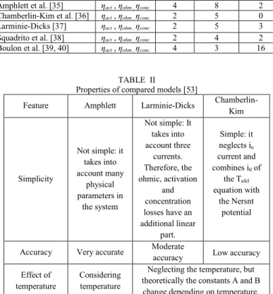
According to Table I, the models suggested by Srinivasan [33]and Mann [34] do not consider the influence of concentration loss (ηconc) in the output voltage due to the fact that it has a minimal effect on its estimation. The performed parametric study in [52], regarding the influence of activation losses (ηact), ohmic losses (ηohm), concentration losses (ηconc) and Nernst potential (OCV) on the voltage estimation, confirms this assumption. However, this study shows that excluding the concentration loss, which occurs in high current region, leads to inaccurate estimation of the maximum power which is very important for the purpose of this paper. In this respect, Srinivasan and Mann models are considered as not suitable for the maximum power mode based cold start-up strategy. In [53], the models introduced by Amphlett, Larminie-Dicks, and Chamberlin-Kim are experimentally compared in terms of parameters quantification, granularity, and accuracy. The obtained results of the conducted study are summarized in Table II. According to this table, Amphlett model is the most accurate one while Chamberlin-Kim model has the maximum error. Moreover, Larminie-Dick has a moderate accuracy. The most important point regarding Larminie-Dick and Chamberlin-Kim models is that they are both based on the operating current and ignore the effect of temperature and pressure on the PEMFC voltage estimation. This, in turn, means that the voltage estimation precision of these two models noticeably decreases when the operating conditions change, which is the case in a PEMFC system. In fact, the operating conditions and the state of health of a PEMFC are variable and Amphlett model can operate in a wider operating range in such conditions. It should be noted that even by estimating the parameters of Larminie-Dick and Chamberlin-Kim models online, their performance cannot be as good as Amphlett model since temperature and pressure are measured input signals in Amphlett model while in the other two ones they are considered as uncertainties and can decrease the estimation quality. Therefore, Larminie-Dick and Chamberlin-Kim model are being excluded from subfreezing condition analysis of this paper and the three models, namely Squadrito, Boulon, and Amphlett remain. These three models will be experimentally compared to identify the best model for reproducing the behavior of the
5
PEMFC at low temperatures and facing different levels of degradation. More details about the selected models are given hereinafter.
TABLE I
Semi-empirical models of PEMFC
Author Considered regimes MeasurNumber of parameters ed Unknown Constant
Srinivasan et al. [33] ηact , ηohm 3 5 1
Mann et al. [34] ηact , ηohm 4 10 2
Amphlett et al. [35] ηact , ηohm , ηconc 4 8 2
Chamberlin-Kim et al. [36] ηact , ηohm , ηconc 2 5 0
Larminie-Dicks [37] ηact , ηohm , ηconc 2 5 3
Squadrito et al. [38] ηact , ηohm , ηconc 2 4 2
Boulon et al. [39, 40] ηact , ηohm , ηconc 4 3 16
TABLE II
Properties of compared models [53]
Feature Amphlett Larminie-Dicks Chamberlin-Kim
Simplicity Not simple: it takes into account many physical parameters in the system Not simple: It takes into account three currents. Therefore, the ohmic, activation and concentration losses have an additional linear part. Simple: it neglects in current and combines i0 of the Tafel equation with the Nersnt potential
Accuracy Very accurate Moderate accuracy Low accuracy Effect of
temperature Considering temperature
Neglecting the temperature, but theoretically the constants A and B
change depending on temperature.
3.1 Description of the selected semi-empirical models
As explained before, all the selected semi-empirical models describe the behavior of a PEMFC stack by predicting the polarization curve. The cell potential is calculated by :
𝑉𝑐𝑒𝑙𝑙= 𝐸𝑛𝑒𝑠𝑛𝑠𝑡− 𝜂𝑎𝑐𝑡− 𝜂𝑜ℎ𝑚− 𝜂𝑐𝑜𝑛𝑐 Eq. (1)
Each of these regimes can be defined as follows:
𝐸𝑛𝑒𝑠𝑛𝑠𝑡= { Squadrito: 𝑉0 Amphlett: 1.229 − 0.85 × 10⁻³(𝑇 𝑓𝑐− 298.15) + 4.3085 × 10⁻⁵𝑇 𝑓𝑐[𝑙𝑛(𝑃𝐻2) + 0.5𝑙 𝑛( 𝑃𝑂2) 𝐵𝑜𝑢𝑙𝑜𝑛: 1.229 − 0.85 × 10⁻³(𝑇 𝑓𝑐− 298.15) + 4.3085 × 10⁻⁵𝑇 𝑓𝑐[𝑙𝑛(𝑃𝐻2) + 0.5𝑙 𝑛( 𝑃𝑂2) Eq. (2)
6 𝜉𝑎𝑐𝑡= { Squadrito: 𝑏 log(𝑖𝑓𝑐) Amphlett: {𝜉1+ 𝜉2𝑇𝑓𝑐+ 𝜉3𝑇𝑓𝑐𝑙𝑜𝑔(𝐶𝑂2) + 𝜉4𝑇𝑓𝑐𝑙𝑜𝑔(𝑖𝑓𝑐) 𝐶𝑂2= 𝑃𝑂2 5.08×10⁶ 𝑒𝑥𝑝(−498 𝑇 𝑓𝑐 ⁄ ) Boulon: { 𝐾1 𝑅+𝑇𝑓𝑐 𝐹 log ( 𝑗+𝑗𝑙𝑜𝑠𝑠 𝑗0 ) 𝑗0= 𝛾 𝑃𝑂2 𝑃0 exp (− 𝐸𝑐 𝑅𝑇𝑓𝑐(1 − 𝑇𝑓𝑐 𝑇0)) Eq. (3) 𝜉𝑜ℎ𝑚= { Squadrito: 𝑟 𝑖𝑓𝑐 Amphlett: −𝑖𝑓𝑐𝑅𝑖𝑛𝑡𝑒𝑟𝑛𝑎𝑙= −𝑖𝑓𝑐(𝜇1+ 𝜇2𝑇𝑓𝑐+ 𝜇3𝑖𝑓𝑐) Boulon: { 𝑅𝑚 𝑖𝑓𝑐 𝑅𝑚= 𝐾2 𝑡𝑚𝑏 𝑏11∗Ʌ𝑚𝑏−𝑏12 exp (−𝛼 ( 1 𝑇0− 1 𝑇𝑓𝑐)) Eq. (4) 𝜉𝑐𝑜𝑛𝑐= { Squadrito: 𝛼(𝑖𝑓𝑐)𝑘log(1 − 𝛽𝑖𝑓𝑐) Amphlett: 𝐵 𝑙𝑜𝑔 (1 − 𝐽𝑓𝑐 𝐽𝑚𝑎𝑥) Boulon: 𝐾3 𝑇𝑓𝑐 log (1 − 𝑗 𝑗𝐿) Eq. (5)
where 𝑉0 is the open-circuit voltage (V), 𝑇𝑓𝑐 is the stack temperature (K), 𝑃𝐻2 is the partial pressure of the hydrogen on the anode side (Pa), and 𝑃𝑂2 is the pressure of the oxygen on the cathode side (Pa), 𝑖𝑓𝑐 is the stack current (A), 𝐶𝑂2 is the oxygen concentration (mol.cm-3), 𝐽𝑓𝑐 is the current density (A.cm-2), and 𝐽𝑚𝑎𝑥 is the limiting current density. The explanation of the other empirical parameters for Amphlett, Squadrito, and Boulon’s model can be found in [35, 38-40] respectively.
4 THE RECURSIVE IDENTIFICATION ALGORITHM
The performance drifts of a PEMFC stack stem from two important factors. The first one is the degradation phenomena and/or lifetime ageing which happen slowly through the time depending on how the PEMFC stack is being used. The second factor is the variation of the operating conditions such as temperature, pressure, humidity, etc. which can happen at any time during the operation of the stack. These drifts make the parameters of a PEMFC model time-varying and therefore the use of a recursive identification technique necessity to keep track of these variations as time goes by several identification techniques such as recursive least square (RLS), recursive maximum likelihood (RML), Kalman filter, and extended Kalman filter [49, 54]. In [54], the performance of RLS and RML has been compared for the parameter identification of a PEMFC model and concluded that RML has more robustness while confronting noise in the measurements. In this work, RML is used to identify the parameters of interest in the selected model. It should be noted that all the three models predict the nonlinear behavior of the PEMFC. However, the targeted parameters for identification are linear. RML is quite similar to the well-known RLS algorithm and the main distinction is that the disturbance (𝜈(𝑡)) influencing the targeted output is modeled as a moving average of a serially uncorrelated white noise sequence [54]. In this regard, the unobserved components (𝑒(𝑡), 𝑒(𝑡 − 1), … , 𝑒(𝑡 − 𝑟)) are approximated by the residuals, which are the values of the obtained error (E(t)). RML algorithm can be formulated as: 𝑦(𝑡) = 𝜃(𝑡)𝑇𝜑(𝑡) + 𝜈(𝑡) Eq. (6) 𝜈(𝑡) = 𝑒(𝑡) + 𝑐1(𝑡)𝑒(𝑡 − 1) + ⋯ + 𝑐𝑟(𝑡)𝑒(𝑡 − 𝑟) Eq. (7) 𝜃(𝑡) = 𝜃(𝑡 − 1) + 𝑘(𝑡)𝐸(𝑡) Eq. (8) 𝑘(𝑡) = 𝜆−1𝑃(𝑡 − 1) 𝛹(𝑡) (1 + 𝜆⁄ −1𝛹𝑇(𝑡)𝑃(𝑡 − 1)𝛹(𝑡)) Eq. (9) 𝛹(𝑡) = 𝜑(𝑡) 𝐶(𝑞⁄ −1) Eq. (10) 𝑃(𝑡) = 𝜆−1𝑃(𝑡 − 1) − 𝜆−1𝑘(𝑡)𝛹𝑇(𝑡)𝑃(𝑡 − 1) + 𝐵𝐼 Eq. (11)
7 { 𝜆(𝑡) = 𝜔 – (1 – 𝜔 𝜑𝑇(𝑡)𝑃(𝑡 – 1)𝜑(𝑡)) ; 𝑖𝑓 𝜑𝑇(𝑡)𝑃(𝑡 – 1)𝜑(𝑡) > 0 𝜆(𝑡) = 1; 𝑖𝑓 𝜑𝑇(𝑡)𝑃(𝑡 – 1)𝜑(𝑡) = 0 𝐸(𝑡) = 𝑢(𝑡) − 𝜑𝑇(𝑡) 𝜃(𝑡 − 1) Eq. (13)
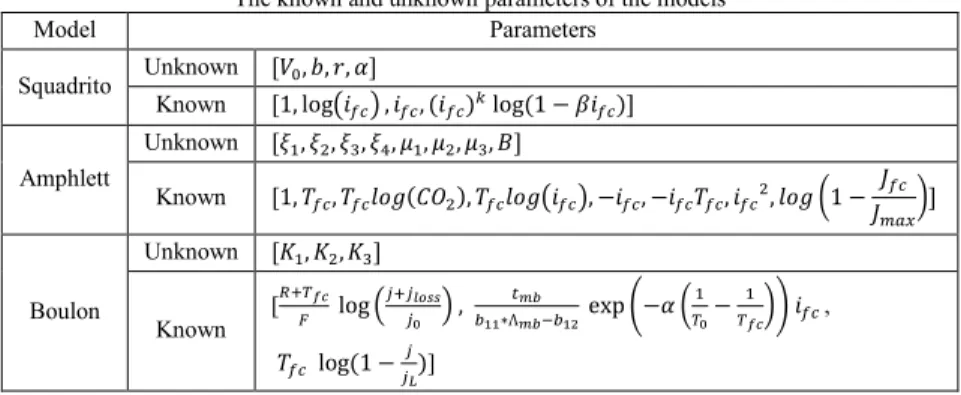
where 𝑦(𝑡) is the estimated output, 𝜃(𝑡) is the parameter vector (unknown parameter vectors defined in Table III, 𝜑(𝑡) is the regression vector (known parameter vectors listed in Table III), 𝜈(𝑡) is the uncertainty on the output, 𝑒(𝑡) is the residuals calculated by the values of error, 𝑐 is the added parameter for error prediction, 𝑘(𝑡) is the Kalman gain, 𝐸(𝑡) is the error, 𝜆 is a directional forgetting factor, 𝛹(𝑡) is a filter, 𝑃(𝑡) is the covariance matrix, 𝐵 is a constant that increases the covariance matrix instantly, 𝐼 is the identity matrix, 𝐶 is the estimated polynomial of the parameter 𝑐 (1 + 𝑐1𝑞−1+ ⋯ + 𝑐𝑟𝑞−𝑟), 𝑞−1 is the delayed operator, 𝜔 is the forgetting factor (0< 𝜔 <1), and 𝑢(𝑡) is the measured output. The number of parameters 𝑐, determined by 𝑟 in the formulas, has been considered as three in this work based on some trials. However, it can be increased or decreased in other problems. In this respect, the three parameters of 𝑐1, 𝑐2, and 𝑐3 should be added to the unknown parameter vectors of the three selected semi-empirical models, shown in Table III, and their corresponded residual values (𝑒(𝑡 − 1), 𝑒(𝑡 − 2), and 𝑒(𝑡 − 3)) should be added to the known parameter vectors to perform the parameter identification process. Table III shows the unknown parameters of each model, which need to be estimated by the recursive filter for a good voltage fit, as well as the known parameter vectors.
TABLE III
The known and unknown parameters of the models
Model Parameters
Squadrito Unknown [𝑉0, 𝑏, 𝑟, 𝛼]
Known [1, log(𝑖𝑓𝑐) , 𝑖𝑓𝑐, (𝑖𝑓𝑐)𝑘 log (1 − 𝛽𝑖𝑓𝑐)]
Amphlett Unknown [𝜉1, 𝜉2, 𝜉3, 𝜉4, 𝜇1, 𝜇2, 𝜇3, 𝐵] Known [1, 𝑇𝑓𝑐, 𝑇𝑓𝑐𝑙𝑜𝑔(𝐶𝑂2), 𝑇𝑓𝑐𝑙𝑜𝑔(𝑖𝑓𝑐), −𝑖𝑓𝑐, −𝑖𝑓𝑐𝑇𝑓𝑐, 𝑖𝑓𝑐2, 𝑙𝑜𝑔 (1 − 𝐽𝑓𝑐 𝐽𝑚𝑎𝑥 )] Boulon Unknown [𝐾1, 𝐾2, 𝐾3] Known [ 𝑅+𝑇𝑓𝑐 𝐹 log ( 𝑗+𝑗𝑙𝑜𝑠𝑠 𝑗0 ) , 𝑡𝑚𝑏 𝑏11∗Ʌ𝑚𝑏−𝑏12 exp (−𝛼 ( 1 𝑇0− 1 𝑇𝑓𝑐)) 𝑖𝑓𝑐 , 𝑇𝑓𝑐 log (1 − 𝑗 𝑗𝐿)] 5 EXPERIMENTAL PROCEDURE 5.1 Test bench
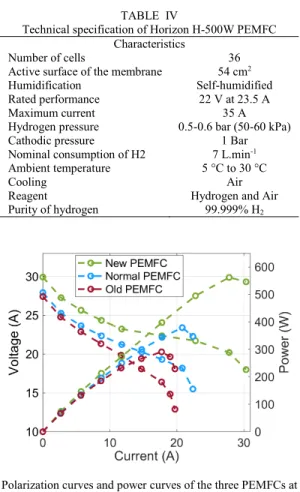
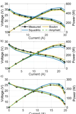
The detailed architecture of the utilized test bench in this work is presented in Fig. 2. As it can be seen, a Horizon H-500 air breathing PEMFC is connected to a National Instrument CompactRIO through a controller where the control of the purge valve, fan speed and hydrogen valve is performed and the acquisition of data (temperature, current, voltage, hydrogen flow) is conducted. A programmable DC electronic load with the maximum power of 1200 W is used to demand power from the PEMFC. To remove the build-up water and nitrogen and refill the anode with fresh hydrogen, the stack is purged every 10 s for the duration of 10 ms. As suggested by the manufacturer, the difference between the atmospheric pressure in the cathode side and the pressure of the PEMFC in the anode side should be kept around 0.5 bar. The PEMFC stack is put inside a climate chamber to test the effect of the sub-freezing temperature condition on the performance of the stack. The explained semi-empirical models and the parameter identification algorithm have been developed in MATLAB and implemented in LabVIEW software via Math Script Module.The characteristics of the used Horizon H-500 air breathing PEMFC are specified in Table IV. It should be mentioned that for the purpose of this work, three Horizon H-500 PEMFCs with different levels of degradation are used. To clarify the difference in the performance of the utilized PEMFCs, their polarization and power curves, obtained at ambient temperature, are presented in Fig. 3. As is seen in this figure, the utilized PEMFCs, which are of the same model, have different maximum powers due to their different states of health. This difference in the rated power of the PEMFCs also justifies the need of online maximum power estimation in such system.
8
Hereinafter, to distinguish the three PEMFCs shown in Fig. 3, a specific name is chosen for each one based on its state of health. The PEMFC with the rated power of 500 W is in its beginning of life and named New PEMFC. The one with almost 300 W is in its end of life and named Old PEMFC. Finally, the one with the rated power of 400 W is presumed to be in its middle of life and named Normal PEMFC.
Fig. 2. The experimental set-up used in this work TABLE IV
Technical specification of Horizon H-500W PEMFC Characteristics
Number of cells 36
Active surface of the membrane 54 cm2
Humidification Self-humidified
Rated performance 22 V at 23.5 A
Maximum current 35 A
Hydrogen pressure
Cathodic pressure 0.5-0.6 bar (50-60 kPa) 1 Bar Nominal consumption of H2 7 L.min-1 Ambient temperature 5 °C to 30 °C Cooling
Reagent
Purity of hydrogen
Air Hydrogen and Air
99.999% H2
Fig. 3. Polarization curves and power curves of the three PEMFCs at 25 ° C
5.2 Procedure
The PEMFC is purged and placed inside a climatic chamber to cool down the PEMFC until the desired start-up temperatures. A current profile is requested from the PEMFCs by means of the DC electronic load and the measured data from the PEMFC are sent to the PC through the CompactRIO to be employed in the implemented model for identification process. The RML algorithm receives the measured current, voltage, and temperature data via Ethernet communication every 100 ms. Subsequently, it identifies the parameters
9
of the model at each sequence, and the updated model is used to plot the PEMFC polarization curve. The polarization curves estimated by the three models will be compared with the measured curves in terms of different operating temperatures (-10 °C and 1 °C), and degradation levels (three PEMFC). The RML algorithm continuously updates the parameters of the models. Therefore, the initial parameters must be well chosen to avoid the divergence of the algorithm. Identification of the initial parameters is done by Curve Fitting Toolbox ™ of the MATLAB software. This toolbox uses least squares methods to identify the initial parameters.
6 EXPERIMENTAL RESULTS
Fig. 4 shows the current profile used to perform the test and the corresponded measured voltage and temperature. The measured current, voltage, and temperature data are sent to the PEMFC model to estimate PEMFC voltage by using the RML identification algorithm in a real-time process, and then the output voltages estimated by the three models are compared to the measured ones, as shown in Fig. 5. To avoid the repetition of the result’s presentation, only the estimation process of the Normal PEMFC (400 W) case study is shown in Fig. 5. As it can be seen in this figure, all the models show acceptable estimation of the voltage. The error between the measured and estimated voltage is very small for the three models. Some peaks are caused by the rapid PEMFC current change, but they rapidly decrease, as shown in Fig. 5.b. From this voltage estimation analysis, it is very difficult to judge the performance of the models and draw a sharp distinction among them. It is worth noting that the identification algorithm tries to minimize the error of estimated voltage for a single point, regardless of the fluctuation of the parameters or the behavior of the system. Therefore, an accurate estimation of the PEMFC voltage does not guarantee that the model has sufficient accuracy, and the physical relevance of the results must be studied deeper through the polarization curve estimation. In this respect, the estimation of the polarization curve for each of the PEMFCs (New, Normal, and Old) in two different operating temperatures of 1 °C and -10 °C is studied hereinafter to distinguish the most suitable semi-empirical model for the cold start application.
10
Fig. 5. The estimated voltage of the Noemal PEMFC (400 W) with the three models (a), and the relative error (|1 −Vestimated Vmeasured |)
between measured voltage and estimated voltage (b).
Fig. 6 presents the polarization and power curves estimated by the three semi-empirical models for different levels of degradation at 1 °C. From this figure, it is clear that Amphlett model comes first, Boulon second, and Squadrito third regarding the estimation accuracy. These results also show that the sole precise voltage estimation cannot guarantee that the selected model has enough capability to predict the characteristics of a PEMFC such as polarization curve. Therefore, the use of another verification tool other than voltage seems to be necessary. Fig. 7 presents the estimation of polarization and power curves at -10 °C for different cases. This figure confirms that even in sub-zero operating temperature condition, the performance of the Amphlett model is better than the other two models. The malfunction of Squadrito model is due to the fact that it does not consider the temperature variation and, therefore, the parameters vary a lot to reduce the voltage estimation error. This variation decreases the voltage estimation error while deviating from the reference polarization curve. Regarding the Boulon model, the only reason for its less accuracy compared to Amphlett model is the existence of several physical or specific variables which need to be determined by some measurements for each type of PEMFC. Once these variables are set incorrectly, the model cannot predict the characteristics curves very accurately.
11
Fig. 6. Polarization Curve estimation at 1 °C for: a) New PEMFC (500W), b) Normal PEMFC (400W), and c) Old PEMFC (300W)
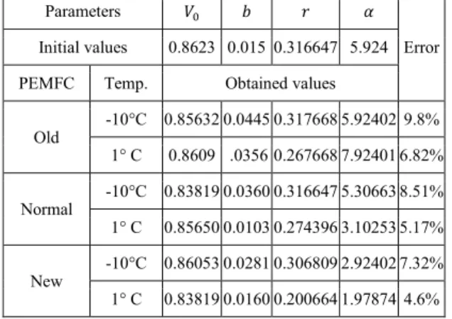
Fig. 7. Polarization Curve estimation at -10 °C for: a) New PEMFC (500W), b) Normal PEMFC (400W), and c) Old PEMFC (300W) Table V, Table VI, and Table VII represent the initial and estimated parameters of the three models and there corresponding estimation errors. The reported error value is the mean of relative error in terms of percentage. According to these tables, Amphlett model presents the smallest error between the estimated and measured curves for the three PEMFCs and for the different operating temperatures.
12 TABLE V
The obtained values for the Squadrito et al. model by the identification process
Parameters 𝑉0 𝑏 𝑟 𝛼
Error Initial values 0.8623 0.015 0.316647 5.924 PEMFC Temp. Obtained values
Old -10°C 0.85632 0.0445 0.317668 5.92402 9.8% 1° C 0.8609 .0356 0.267668 7.92401 6.82% Normal -10°C 0.83819 0.0360 0.316647 5.30663 8.51% 1° C 0.85650 0.0103 0.274396 3.10253 5.17% New -10°C 0.86053 0.0281 0.306809 2.92402 7.32% 1° C 0.83819 0.0160 0.200664 1.97874 4.6% TABLE VI
The obtained values for the Amthlett et al. model by the identification process
Parameters 𝜉1 𝜉2 𝜉3 𝜉4 𝜇1 𝜇2 𝜇3 𝐵
Error Initial values -2.12 5 e-3 -3.6 e-5 -2.9 e-4 -6.82 e-2 2.2 e-4 1.1 e-4 3.249
PEMFC Temp. Obtained values
Old -10°C -2.12 5 e-3 -8.08 e-5 -2.80 e-4 -6.82 e-2 2.2 e-4 1.1 e-4 3.293 3.97% 1° C -2.12 5 e-3 -7.29 e-5 -2.82 e-4 -6.7 e-2 2.2 e-4 1.1 e-4 3.273 1.94% Normal -10°C -2.12 5 e-3 -1.24 e-4 -2.72 e-4 -6.68 e-2 2.2 e-4 1.1 e-4 3.263 3.53% 1° C -2.12 5 e-3 -1.07 e-4 -2.76 e-4 -6.52 e-2 2.2 e-4 1.1 e-4 3.253 1.41% New -10°C -2.12 5 e-3 -1.47 e-4 -2.66 e-4 -6.45 e-2 2.2 e-4 1.1 e-4 3.243 3.29% 1° C -2.12 5 e-3 -1.5 e-4 -2.63 e-4 -6.32 e-2 2.2 e-4 1.1 e-4 3.223 1.24%
TABLE VII
The obtained values for the Boulon et al. model by the identification process
Parameters K1 K2 K3
Error Initial values 1.4001 1.9389 1.4 PEMFC Temp. Obtained values
Old -10°C 1.4921 1.6910 1.6910 7.39 % 1° C 1.4015 1.6891 1.6891 4.11% Normal -10°C 1.4921 1.4831 1.4831 6.80% 1° C 1.3956 1.463 1.463 3.90% New -10°C 1.4231 1.391 1.391 6.25% 1° C 1.3841 1.301 1.301 3.53%
Fig. 6 and 7 show that Boulon and Amphlett models are more accurate in terms of open-circuit voltage (ENernst) estimation because they are based on a general formula that takes into account PEMFC temperature and hydrogen and oxygen pressures. In contrast, Squadrito model estimates ENernst from PEMFC current and voltage measurements which leads to less accuracy compared to Boulon and Amphlett models. Concerning activation loss region, Amphlett model is more accurate than the other two models since it requires the estimation of four empirical coefficients based on fluid mechanics, thermodynamics, electrochemistry, and
13
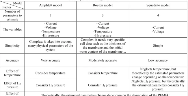
they also depend on material and type of PEMFC. However, Boulon and Squadrito models require the estimation of a single parameter, which is an empirical coefficient based on PEMFC temperature, degradation, and membrane moisture. Indeed, the consideration of more parameters for Amphlett model brings more accuracy but increases the calculation time. Concerning the linear part of the polarization curve where the voltage drop is mainly due to the electronic and ionic internal resistances, Amphlett model is still the most accurate as its formula is more general and does not require specific data such as membrane thickness, active membrane area and membrane moisture content, which are only available for a limited number of fuel cells. With regard to the concentration loss, characterized by a rapid voltage drop, the three models almost consider the same formula. However, the inaccuracy of estimation in activation and ohmic zones affects the estimation quality in the concentration zone, which means that Amphlett model has better performance in this region as well. Table VIII summarizes the discussed points regarding the strengths and weakness of the tested models. The reason for establishing such a good precedent by the Amphlett model can be the generic formulation of is semi-empirical equations. In fact, it has eight parameters (four for the activation regime, three for the ohmic regime, and one for the concentration regime), which need to be tuned. So far, it has been shown that this model is able to acceptably estimate the polarization curve of a PEMFC in different conditions. However, the values of the estimated parameters are different for each case. It should be reminded that this model is effective as long as the information regarding the whole performance is needed which is the case in this manuscript. For detailed physical interpretations, other models and electrochemical methods should be considered.
TABLE VIII
Summary of the investigated models Model
Factor Amphlett model Boulon model Squadrito model
Number of parameters to estimate 7 3 4 The variables - Current -Voltage -Temperature -H2 pressure - Current -Voltage -Temperature -H2 pressure -Current -Voltage Simplicity many physical parameters of the Complex: it takes into account
system
Complex: it needs very specific cell data such as the thickness of the membrane and the initial water content of the membrane ...
Simple
Accuracy Very accurate Moderately accurate Low accuracy
Effect of
temperature Consider temperature Consider temperature
Neglects temperature, but theoretically the estimated parameters change depending on the temperature Effect of H2
pressure Consider H2 pressure Consider H2 pressure
Neglects H2 pressure, but theoretically the estimated parameters consider H2
pressure. Effect of
degradation Theoretically, the estimated parameters change depending on the degradation of the PEMFC.
7 CONCLUSION
The performance of maximum power mode based cold start strategies in a PEMFC stack highly depends on the selection of a precise model. However, very few studies have focused on the performance evaluation of PEMFC models in sub-freezing conditions. In this respect, three semi-empirical models, namely Amphlett, Boulon, and Squadrito, are experimentally tested and compared in this paper with a view to selecting the most accurate one for predicting the characteristics of a PEMFC stack in sub-zero temperature condition. The performance of the selected models is thoroughly investigated regarding the estimation of polarization and power curves for three 500 W open cathode PEMFCs with different levels of degradation under two operating temperatures (1℃ and -10℃). To carry out the comparative study, a current profile is applied to the PEMFCs, and the measured data (current, temperature, and voltage) are transferred to the RML algorithm to tune the parameters of the models in real-time by minimizing the error between the estimated voltage and the
14
measured one. Once the parameters of the models are estimated, the models are used for predicting the characteristics curves of the stacks. The conducted study shows that the model proposed by Amphlett et al. has higher accuracy than the other two ones regarding the characteristic’s prediction in above and below zero temperature conditions. This higher precision is achieved by Amphlett model due to two important factors: first, its stronger thermodynamics background compared to Squadrito model, and second, its less dependency on specific data, such as water content and membrane thickness, compared to Boulon model. While this manuscript has demonstrated the potential of the suggested model for developing a maximum power mode cold start-up strategy, some opportunities for extending the scope of this paper remain as follows:
Future works should focus on the use of Amphlett model in the design of maximum power mode PEMFC cold start strategies from -20℃. To this end, more focus should be given to the development of an online ice estimation algorithm combined with a hybrid cold start solution. This algorithm should be based on an adaptive maximum cold start mode, as the main cold start solution, and an external heating method used when cathode catalyst layer is blocked by ice.
Another direction to extend the perspectives of this work is to focus on the experimental performance evaluation of the proposed PEMFC model with the maximum power mode cold start-up strategy with a closed-cathode PEMFC system.
ACKNOWLEDGEMENTS
This work was supported in part by the Bureau de l’éfficacité et de l’innovation énergétique, Ministère des Ressources Naturelles et de la Faune du Québec, the Natural Sciences and Engineering Research Council of Canada (NSERC), the Fonds de recherche du Québec–Nature et technologies (FRQNT), and Canada Research Chairs program.
REFERENCES
[1] H. Jiang et al., "Modeling of Fuel Cell Cold Start and Dimension Reduction Simplification Method,"
Journal of The Electrochemical Society, vol. 167, no. 4, p. 044501, 2020.
[2] S. Curtin and J. Gangi, "Fuel Cell Technologies Market Report," U.S. Department Of ENERGY, 2017.
[3] A. A. Amamou, S. Kelouwani, L. Boulon, and K. Agbossou, "A Comprehensive Review of Solutions and Strategies for Cold Start of Automotive Proton Exchange Membrane Fuel Cells,"
IEEE Access, vol. 4, pp. 4989-5002, 2016.
[4] L. Wei, A. M. Dafalla, and F. Jiang, "Effects of reactants/coolant non-uniform inflow on the cold start performance of PEMFC stack," International Journal of Hydrogen Energy, 2020/03/27/ 2020. [5] L. Yao, F. Ma, J. Peng, J. Zhang, Y. Zhang, and J. Shi, "Analysis of the Failure Modes in the Polymer Electrolyte Fuel Cell Cold-Start Process—Anode Dehydration or Cathode Pore Blockage,"
Energies, vol. 13, no. 1, p. 256, 2020.
[6] L. Yao, J. Peng, J.-b. Zhang, and Y.-j. Zhang, "Numerical investigation of cold-start behavior of polymer electrolyte fuel cells in the presence of super-cooled water," International Journal of
Hydrogen Energy, vol. 43, no. 32, pp. 15505-15520, 2018/08/09/ 2018.
[7] K. Han, B. K. Hong, S. H. Kim, B. K. Ahn, and T. W. Lim, "Influence of anisotropic bending stiffness of gas diffusion layers on the degradation behavior of polymer electrolyte membrane fuel cells under freezing conditions," International Journal of Hydrogen Energy, vol. 36, no. 19, pp. 12452-12464, 9// 2011.
[8] W. Schmittinger and A. Vahidi, "A review of the main parameters influencing long-term performance and durability of PEM fuel cells," Journal of Power Sources, vol. 180, no. 1, pp. 1-14, 5/15/ 2008.
[9] L. Wei, Z. Liao, Z. Suo, X. Chen, and F. Jiang, "Numerical study of cold start performance of proton exchange membrane fuel cell with coolant circulation," International Journal of Hydrogen Energy, vol. 44, no. 39, pp. 22160-22172, 2019/08/13/ 2019.
[10] Y. Luo and K. Jiao, "Cold start of proton exchange membrane fuel cell," Progress in Energy and
15
[11] M. Procter, Y. Fukuyama, R. Fellows, and T. Shiomi, "Shutdown and storage method for fuel cell
system at below freezing temperatures," US, 2016. Available:
https://patents.google.com/patent/US10547067B2/en#patentCitations.
[12] B. J. Clingerman et al., "Fuel cell system water management strategy for freeze capability," US Patent 2007/0298289 A1, 2007. Available: https://www.google.ca/patents/US20070298289. [13] A. A. Pesaran et al., PEM fuel cell freeze and rapid startup investigation. Golden, Colo.: National
Renewable Energy Laboratory, 2005.
[14] R. J. Assarabowski, W. T. Unkert, L. A. Bach, A. P. Grasso, and B. C. Olsommer, "Method and apparatus for preventing water in fuel cell power plants from freezing during storage," US Patent 6,797,421 B2, 2004. Available: https://www.google.com/patents/US6797421.
[15] M. Khandelwal, S. Lee, and M. M. Mench, "One-dimensional thermal model of cold-start in a polymer electrolyte fuel cell stack," Journal of Power Sources, vol. 172, no. 2, pp. 816-830, 10/25/ 2007.
[16] Y. Zhou, Y. Luo, S. Yu, and K. Jiao, "Modeling of cold start processes and performance optimization for proton exchange membrane fuel cell stacks," Journal of Power Sources, vol. 247, pp. 738-748, 2014.
[17] K. Jiao, I. E. Alaefour, G. Karimi, and X. Li, "Simultaneous measurement of current and temperature distributions in a proton exchange membrane fuel cell during cold start processes," Electrochimica
Acta, vol. 56, no. 8, pp. 2967-2982, 3/1/ 2011.
[18] N. Henao, S. Kelouwani, K. Agbossou, and Y. Dubé, "Proton exchange membrane fuel cells cold startup global strategy for fuel cell plug-in hybrid electric vehicle," Journal of Power Sources, vol. 220, no. 0, pp. 31-41, 12/15/ 2012.
[19] R. Lin, Y. Weng, Y. Li, X. Lin, S. Xu, and J. Ma, "Internal behavior of segmented fuel cell during cold start," International Journal of Hydrogen Energy, vol. 39, no. 28, pp. 16025-16035, 9/23/ 2014. [20] Y. Hishinuma, T. Chikahisa, F. Kagami, and T. Ogawa, "The design and performance of a PEFC at a temperature below freezing," JSME International Journal Series B Fluids and Thermal
Engineering, vol. 47, no. 2, pp. 235-241, 2004.
[21] Q. Guo, Y. Luo, and K. Jiao, "Modeling of assisted cold start processes with anode catalytic hydrogen-oxygen reaction in proton exchange membrane fuel cell," International Journal of
Hydrogen Energy, vol. 38, no. 2, pp. 1004-1015, 2013.
[22] F. Jiang and C.-Y. Wang, "Potentiostatic start-up of PEMFCs from subzero temperatures," Journal
of the Electrochemical Society, vol. 155, no. 7, pp. B743-B751, 2008 2008.
[23] R. Lin, Y. Weng, X. Lin, and F. Xiong, "Rapid cold start of proton exchange membrane fuel cells by the printed circuit board technology," International Journal of Hydrogen Energy, vol. 39, no. 32, pp. 18369-18378, 10/31/ 2014.
[24] R. K. Ahluwalia and X. Wang, "Rapid self-start of polymer electrolyte fuel cell stacks from subfreezing temperatures," Journal of Power Sources, vol. 162, no. 1, pp. 502-512, 11/8/ 2006. [25] L. Li, S. Wang, L. Yue, and G. Wang, "Cold-start icing characteristics of proton-exchange
membrane fuel cells," International Journal of Hydrogen Energy, vol. 44, no. 23, pp. 12033-12042, 2019/05/03/ 2019.
[26] Q. Du, B. Jia, Y. Luo, J. Chen, Y. Zhou, and K. Jiao, "Maximum power cold start mode of proton exchange membrane fuel cell," International Journal of Hydrogen Energy, vol. 39, no. 16, pp. 8390-8400, 2014.
[27] A. Amamou, M. Kandidayeni, L. Boulon, and S. Kelouwani, "Real time adaptive efficient cold start strategy for proton exchange membrane fuel cells," Applied Energy, vol. 216, pp. 21-30, 2018/04/15 2018.
[28] A. Amamou, L. Boulon, and S.Kelouwani, "Comparison of self cold start strategies of automotive Proton Exchange Membrane Fuel Cell," presented at the International Conference on Industrial Technology, Lyon, France, 2018.
[29] M. Ibrahim, N. Y. Steiner, S. Jemei, and D. Hissel, "Wavelet-Based Approach for Online Fuel Cell Remaining Useful Lifetime Prediction," IEEE Transactions on Industrial Electronics, vol. 63, no. 8, pp. 5057-5068, 2016.
[30] D. Zhong et al., "Low temperature durability and consistency analysis of proton exchange membrane fuel cell stack based on comprehensive characterizations," Applied Energy, vol. 264, p. 114626, 2020.
16
[31] D. Zhou, F. Gao, E. Breaz, A. Ravey, A. Miraoui, and K. Zhang, "Dynamic Phenomena Coupling Analysis and Modeling of Proton Exchange Membrane Fuel Cells," IEEE Transactions on Energy
Conversion, vol. 31, no. 4, pp. 1399-1412, 2016.
[32] D. Zhao, F. Gao, P. Massonnat, M. Dou, and A. Miraoui, "Parameter Sensitivity Analysis and Local Temperature Distribution Effect for a PEMFC System," IEEE Transactions on Energy Conversion, vol. 30, no. 3, pp. 1008-1018, 2015.
[33] S. Srinivasan, E. A. Ticianelli, C. R. Derouin, and A. Redondo, "Advances in solid polymer electrolyte fuel cell technology with low platinum loading electrodes," Journal of Power Sources, vol. 22, no. 3, pp. 359-375, 1988/03/01/ 1988.
[34] R. F. Mann, J. C. Amphlett, M. A. I. Hooper, H. M. Jensen, B. A. Peppley, and P. R. Roberge, " Development and application of a generalised steady-state electrochemical model for a PEM fuel cell," Journal of Power Sources, vol. 86, no. 1, pp. 173-180, 2000/03/01/ 2000.
[35] J. C. Amphlett, R. F. Mann, B. A. Peppley, P. R. Roberge, and A. Rodrigues, "A model predicting transient responses of proton exchange membrane fuel cells," Journal of Power Sources, vol. 61, no. 1, pp. 183-188, 1996/07/01/ 1996.
[36] J. Kim, S. M. Lee, S. Srinivasan, and C. E. Chamberlin, "Modeling of Proton Exchange Membrane Fuel Cell Performance with an Empirical Equation," Journal of The Electrochemical Society, vol. 142, no. 8, pp. 2670-2674, August 1, 1995 1995.
[37] J. Larminie and A. Dicks, 245Fuel Cell Systems Explained, Second Edition. 2003.
[38] G. Squadrito, G. Maggio, E. Passalacqua, F. Lufrano, and A. Patti, "An empirical equation for polymer electrolyte fuel cell (PEFC) behaviour," Journal of Applied Electrochemistry, journal article vol. 29, no. 12, pp. 1449-1455, 1999.
[39] L. Boulon, K. Agbossou, D. Hissel, P. Sicard, A. Bouscayrol, and M. C. Péra, "A macroscopic PEM fuel cell model including water phenomena for vehicle simulation," Renewable Energy, vol. 46, pp. 81-91, 2012/10/01/ 2012.
[40] N. Marx, D. Hissel, F. Gustin, L. Boulon, and K. Agbossou, "On the sizing and energy management of an hybrid multistack fuel cell – Battery system for automotive applications," International
Journal of Hydrogen Energy, vol. 42, no. 2, pp. 1518-1526, 2017/01/12/ 2017.
[41] G. Gwak and H. Ju, "A rapid start-up strategy for polymer electrolyte fuel cells at subzero temperatures based on control of the operating current density," International Journal of Hydrogen
Energy, vol. 40, no. 35, pp. 11989-11997, 9/21/ 2015.
[42] A. K. Al-Othman, N. A. Ahmed, F. S. Al-Fares, and M. E. AlSharidah, "Parameter Identification of PEM Fuel Cell Using Quantum-Based Optimization Method," Arabian Journal for Science and
Engineering, journal article vol. 40, no. 9, pp. 2619-2628, September 01 2015.
[43] W. Pan, P. Li, Q. Gan, X. Chen, F. Wang, and G. Dai, "Thermal stability analysis of cold start processes in PEM fuel cells," Applied Energy, vol. 261, p. 114430, 2020.
[44] Y. Saygili, I. Eroglu, and S. Kincal, "Model based temperature controller development for water cooled PEM fuel cell systems," International Journal of Hydrogen Energy, vol. 40, no. 1, pp. 615-622, 2015/01/05/ 2015.
[45] N. Bizon, "On tracking robustness in adaptive extremum seeking control of the fuel cell power plants," Applied Energy, vol. 87, no. 10, pp. 3115-3130, 2010/10/01/ 2010.
[46] K. Ettihir, L. Boulon, and K. Agbossou, "Energy management strategy for a fuel cell hybrid vehicle based on maximum efficiency and maximum power identification," (in En), IET Electrical Systems
in Transportation, vol. 6, no. 4, pp. 261-268, 2016.
[47] L. Jia, Z. Tan, M. Kang, and Z. Zhang, "Experimental investigation on dynamic characteristics of proton exchange membrane fuel cells at subzero temperatures," International Journal of Hydrogen
Energy, vol. 39, no. 21, pp. 11120-11127, 7/15/ 2014.
[48] N. Ade, B. Wilhite, H. Goyette, and M. S. Mannan, "Intensifying vehicular proton exchange membrane fuel cells for safer and durable, design and operation," International Journal of Hydrogen
Energy, vol. 45, no. 7, pp. 5039-5054, 2020.
[49] M. Kandidayeni, A. Macias, A. A. Amamou, L. Boulon, S. Kelouwani, and H. Chaoui, "Overview and benchmark analysis of fuel cell parameters estimation for energy management purposes,"
Journal of Power Sources, vol. 380, pp. 92-104, 2018/03/15/ 2018.
[50] K. Ettihir, M. Higuita Cano, L. Boulon, and K. Agbossou, "Design of an adaptive EMS for fuel cell vehicles," International Journal of Hydrogen Energy, vol. 42, no. 2, pp. 1481-1489, 2017/01/12/ 2017.
17
[51] Y. Chen and N. Wang, "Cuckoo search algorithm with explosion operator for modeling proton exchange membrane fuel cells," International Journal of Hydrogen Energy, vol. 44, no. 5, pp. 3075-3087, 2019.
[52] K. Ettihir, L. Boulon, M. Becherif, K. Agbossou, and H. S. Ramadan, "Online identification of semi-empirical model parameters for PEMFCs," International Journal of Hydrogen Energy, vol. 39, no. 36, pp. 21165-21176, 12/12/ 2014.
[53] A. Saadi, M. Becherif, A. Aboubou, and M. Y. Ayad, "Comparison of proton exchange membrane fuel cell static models," Renewable Energy, vol. 56, pp. 64-71, 2013/08/01/ 2013.
[54] M. Kandidayeni, A. Macias, A. A. Amamou, L. Boulon, and S. Kelouwani, "Comparative Analysis of Two Online Identification Algorithms in a Fuel Cell System," Fuel Cells, vol. 18, no. 3, pp. 347-358, 2018.