Design, Construction, and Experiments with a
Compass Gait Walking Robot
by
Zachary J Jackowski
Submitted to the Department of Mechanical Engineering in partial fulfillment of the requirements for the degree of
Master of Science in Mechanical Engineering at the
MASSACHUSETTS INSTITUTE OF TECHNOLOGY
MASSACHUSTTS INSTIUTE OF TECHNOLOGY
JU.292017]
LIBRARIES
ARCHIVES
June 2011©
Massachusetts Institute of Technology 2011. All rights reserved.Author ... .... ... t of M h i Eniern
Dep artment of Mechan ical Engine ering
(~Th
~ May 6, 2011 Certified by... Certified by... Russell L Tedrake Associate Professor Thesis Supervisor Sangbae Kim Assistant Professor ME Faculty Reader Accepted by David E. HardtDesign, Construction, and Experiments with a Compass
Gait Walking Robot
by
Zachary J Jackowski
Submitted to the Department of Mechanical Engineering on May 6, 2011, in partial fulfillment of the
requirements for the degree of
Master of Science in Mechanical Engineering
Abstract
In recent years a number of new computational techniques for the control of nonlin-ear and underactuated systems have been developed and tested largely in theory and simulation. In order to better understand how these new tools are applied to real systems and to expose areas where the theory is lacking testing on a physical model system is necessary. In this thesis a human scale, free walking, planar bipedal walking robot is designed and several of these new control techniques are tested. These include system identification via simulation error optimization, simulation based LQR-Trees, and transverse stabilization of trajectories. Emphasis is put on the topics of de-signing highly dynamic robots, practical considerations in implementation of these advanced control strategies, and exploring where these techniques need additional development.
Thesis Supervisor: Russell L Tedrake Title: Associate Professor
ME Faculty Reader: Sangbae Kim Title: Assistant Professor
Acknowledgments
I'd like to thank Russ Tedrake for support, both in resources and direct help with
this project in the form of countless discussions and late night code contributions.
I'd also like to thank Anirudha Majumdar for a summer of great help getting the
robot take its first steps and Amy Qian for her help early on with design work and fabrication of the robot's foot actuators. A great deal of thanks is also deserved by everyone else at the Robot Locomotion Group, Michael Levashov for lots of help with dynamics and modeling, Ian Manchester for the many consultations on control theory and direct help with making it work, John Roberts for many useful discussion both on robotics and everything else in life and everyone else for making my years at the lab so enjoyable.
Contents
1 Introduction 15
2 Physical System Design 19
2.1 R obot D esign . . . . 19
2.1.1 Overall Concept . . . . 24
2.1.2 Inertial Measurement Unit... . . . . . . . 27
2.1.3 H ip Sensing . . . . 29
2.1.4 Terrain Sensing . . . . 31
2.2 Mechanical Design.... . . . . . . . . 33
2.2.1 Feet... . . . . . . 33
2.2.2 Body and Bisection Mechanism... . . . . . . . . 38
2.2.3 Hip Actuation . . . . 39
2.2.4 Frame.. . . . . . . . 44
3 System Architecture 51 3.0.5 The Sensor Accumulator . . . . 53
3.0.6 The Command Dispatch . . . . 54
3.0.7 Plug and simulate functionality . . . . 54
3.0.8 System Decentralization... . . . .. 56
4 Control Experiments 57 4.1 Virtual Constraints Experiment. . . . .. 57
4.2 System Model and Identification . . . . 60 7
4.2.1 Impact Model . . . . 62
4.2.2 Actuator Friction . . . . 64
4.2.3 System Identification . . . . 64
4.3 Observer Design . . . . 70
4.4 Harmonic Drive Compliance . . . . 73
4.5 TVLQR Stabilized Trajectories . . . . 77
4.6 Simulation LQR-Trees . . . . 81
4.7 Transverse Stabilized Walking . . . . 84
5 Conclusion 89
List of Figures
1-1 The compass gait with a body is a very simple model of walking which
still reflects all the reasons why walking is a difficult problem. The model can be fully described by the continuous dynamics of these three links along with an instantaneous ground contact which switches the
stance leg. . . . . 17
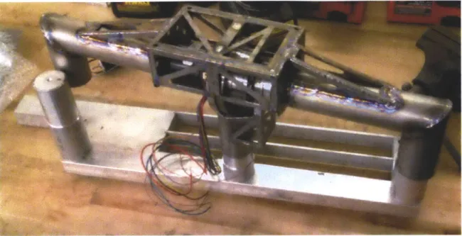
2-1 The full robot, a free walking realization of the simple compass gait model with a body. The robot is a planar walker but has three legs and four feet, with good reason. . . . . 20
2-2 Full image of the acrobot . . . . 21
2-3 Close-up of the acrobot elbow. . . . . 23
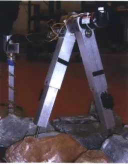
2-4 The lab's old compass gait walker on its boom. . . . . 24
2-5 'Max', an example of a dynamic walking robot with a bisecting body. [2 2] . . . . 2 5 2-6 Encoder flexure bracket. ... ... 30
2-7 Concept drawings for the robot's toe actuators. Lead screw design on the left and cable drive on the right. . . . . 34
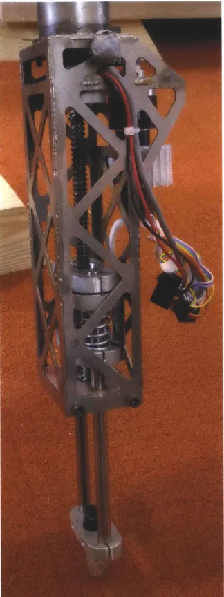
2-8 The robot's series elastic foot actuator. . . . . 35
2-9 The cable which connects to the moving carriage in an inkjet printer was the design inspiration for the similar mechanism in the robot's feet. 36 2-10 The two middle feet branching off from the single middle leg. . . . . . 37
2-11 The original foot configuration where the middle two were bolted back to back. ... ... 38
2-12 The body's angle bisection mechanism. . . . . 40
2-13 Initial concept for a direct drive hip actuator using a frameless motor
and our own aluminum frame. This allows the motor to be built into
the robot in the most efficient way possible. . . . . 41
2-14 Explosion of a Harmonic Drive gearbox from the Harmonic Drive
op-erating principles literature [12]. . . . . 42
2-15 The 30 : 1 ratio Harmonic Drive gearbox used in this robot, showing
the very large driving teeth. Overall diameter of the flex spline (right)
is about 2.5 inches. ... ... ... .43
2-16 The cross roller bearing inside the robot's Harmonic Drive gearbox. . 43
2-17 The robot's titanium sheet metal hip shortly after being welded. The
aluminum fixture was used to hold the three leg connections parallel. 46
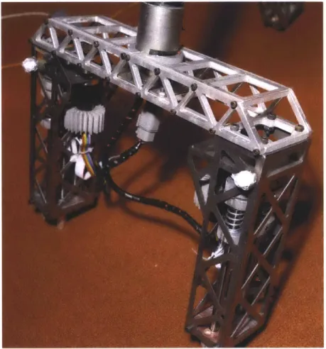
2-18 Initial mockup of the robot without the upper stiffening hoop. .... 47
2-19 The simplified version of the robot's hip box subjected to an end load. 48
2-20 The hip box without the triangular cutouts under the same loading. . 49
3-1 The system control and sensing architecture. . . . . 53 3-2 LCM robot in simulation. . . . . 55 3-3 LCM system controlling the real robot hardware. . . . . 55
4-1 The three-link system model describing the compass gait plant. . . . 61
4-2 Plot of leg velocities resulting from an open loop command played on
the robot versus the simulator. . . . . 63
4-3 The robot setup during system identification. Note the springs
stabi-lizing the system at the equilibrium point. . . . . 67
4-4 Robot with one leg fixed for system identification. . . . . 68
4-5 The final system identification fits, compared against the training data. 71
4-6 Validation plots for the system identification . . . . 72
4-7 Time response of the balancing controller without steps taken to
4-8 Discrete Fourier transform of the torque signal from the good balancing
response... ... 74 4-9 Discrete Fourier transform of the torque signal from the balancing
re-sponse with unwanted high frequency dynamics. . . . . 74
4-10 The bracket the IMU is attached to, possibly flexing as the hip motor
applies large torques to the structure. . . . . 76
4-11 Frequency response of the torque to IMU flex system. . . . . 77
4-12 Frequency response of the torque to inter-leg angle encoder system. . 78
4-13 TVLQR stabilized 'one step rebalance' trajectory. The small ripple along the trajectory is due to the very high controller gains exciting unmodeled high frequency dynamics in the system. Nominal trajectory
is in cyan while the recorded data is in red. . . . . 79
4-14 Plots of the hybrid LQR Tree controller designed to bring the robot to
equilibrium on either of the stance legs. . . . . 85
4-15 The planed periodic trajectory with the step-in trajectory from
equi-librium . . . . 86
4-16 The TVLQR stabilized step-in and first step of the periodic trajectory
List of Tables
Chapter 1
Introduction
As a robot designer and fabricator I come to the area of controls mostly as a consumer but working closely with real theorists. The Robot Locomotion Group has been pro-ducing a tremendous amount of promising new ideas in the field of applied nonlinear control, specifically LQR Trees [19] and transverse stabilization [13]. While mathe-matically well grounded results are important one must look to the actual purpose of the research in order to see that it's only half the story. The other half is how well those techniques work to solve real problems with real hardware and whether they can be implemented successfully and efficiently. This is the end that the compass gait walker project has been working toward. We as a research lab believe that all of the tools required to effectively solve the control of the compass gait currently exist, especially with the development of our LQR Trees method and wanted to develop a hardware platform that can show that fact without a doubt.
The work involved in implementing a full demonstration of our methods on real hardware is also important in and of itself. Previously a great amount of effort has gone into making our methods theoretically sound and working in simulation, but the real goal is almost always making real physical systems work better. Making this happen brings to light a wide variety of new considerations such as how the control theory fits in software system architecture, the constraints of running in real time, and the amenability of common physical systems to the precise modeling our methods require. It is by design that difficulties in this project drive the development of our
work in the future, if not explicitly finding ways to deal with them, knowing of their importance and severity while investigating new methods to steer us away from fragile theories.
While the goals stated above apply for the project as a whole, my goal in this thesis is to record as many of the little bits that fall through the cracks of documentation as possible along with the big ideas. I've been surprised and saddened to find a general absence of design information for those getting started in building highly dynamic robots and lot of effort is lost learning the right order of priorities and rules of thumb. While in design there's no replacement for personal experience, knowing pitfalls ahead of time can mean the success of an entire project.
I think it's safe to say that any robot designer knows, as a few trivial examples,
to make structures lightweight, to validate what can be before committing to build, and to keep control loop delays small. How these individual factors should play in an ecosystem of many competing priorities is usually completely unknown. The designer's art is to figure out how to spread the resources available around to produce something that works. Figuring out the right places to break the bank can mean the difference between a successful ten thousand dollar robot and a failed fifty thousand dollar robot. The fact is that when you're trying to push the boundaries of control something as simple as a bargain bin inertial measurement unit can keep you from solving the problems that actually matter. The same goes for time of course, a week spent simulating the most critical parts of a robot could save months effort later, not only from the first order effects of having to fix what's wrong, but the second order effects of wasted time leading up to deciding band-aid fixes won't cut it and that something needs to be fixed in the first place. I hope to provide an artifact of my design process and how I balanced these competing factors.
Designers work in a different currency from most scientists and engineers because their products are different. The working machine that's produced may not be a great intellectual work, but it's often the real world outlet and test of those works. I hope that the reader will come away from this not so much with an intimate understanding of all the wonderful things I've discovered, but with a feel for the design process of this
kind of machine and the kinds of control methods that can bring it to life. Hopefully the theorists whose work I've drawn on will also be able to see the spots that are still sore and find inspiration for new work in them.
Why we chose to make a simple planar walking robot is an important topic when
it seems like similar things have been done before [10] [22] [5] [11] and even more impressive walking robots have been demonstrated [8] [4] [2] [7]. We feel strongly that in order to understand the real theoretical problems at the heart of these complicated control problems concisely the target system needs to be exactly as complicated as necessary and no more so. The free walking compass gait concept takes a scalpel to complexity and reduces the physical system to the minimum necessary to bring forth all the problems we think matter. It represents highly nonlinear hybrid dynamics with realistic but simple ground contact. It also brings the issues of managing a full robotic system such as carrying its own computation resources into the picture without overshadowing what is going on at the lowest levels.
.03 M3, 13 c3 1c2 M 2, 12 mi, I1
Figure 1-1: The compass gait with a body is a very simple model of walking which still reflects all the reasons why walking is a difficult problem. The model can be fully described by the continuous dynamics of these three links along with an instantaneous ground contact which switches the stance leg.
A system as complicated as ASIMO or BigDog with a very large state adds little
of value as far as understanding goes while the system designed here with its small state and number of actuators still representing all the important problems that need to be solved on the control front. Building the robot in-house puts the expertise with the mechanical and software system in direct contact (often in the same person) with the people developing the control ideas that make it work which is important in
highly dynamic systems such as this where things like loop delays and modelability
can make or break experiments. The robot developed here is also in a performance regime that hasn't been entered by a similar robot before. Careful attention to maximizing actuator performance and ideality has enabled the boundaries of what the system is capable of to be pushed as far out as possible while working within the constraints of an academic lab.
Chapter 2
Physical System Design
With a relatively simple concept and purpose for the robot we thought the actual design of the robot would be very straightforward. The lab already had built a much smaller compass gait walker and I had personally built an acrobot, so we knew more than a few key design points for the robot. There's always more to learn, especially after making a jump in complexity as large as this one and we certainly learned a lot in the process. Hopefully the most important points will all be remembered and recorded here.
2.1
Robot Design
I mean to make a point with the layout of this chapter, that robot design is the
most important design issue in a robot. The defining characteristic of a robot is the integration of sensing, actuation, and decision making into a singular fluid system. The mechanical parts of the robot are inseparable in design from the electrical system that brings them to life and the software systems that breathes intelligence into it all. As a simple example of this, when we designed the acrobot the position encoder for the second link was originally on the back end of the motor, a very clean design decision that integrates the motor assembly and protects the encoder well. Previous experience had shown that kit encoders which rely on user provided bearings had been big sources of problems because of misalignment causing missed counts. Encoders that
Figure 2-1: The full robot, a free walking realization of the simple compass gait model with a body. The robot is a planar walker but has three legs and four feet, with good reason.
Figure 2-2: The acrobot built previous to the design of the compass gait walker. The motor on the first link is connected to the elbow by a long driveshaft. The encoders in question are located on the back of the motor at the top and on the elbow near the bottom of the picture.
integrate their own bearings and housing are much heavier and expensive, so using the encoder on the back of the motor is a big advantage, or at least seemed to be so until we realized the error we had made. The two foot long carbon fiber driveshaft that connected the motor at the shoulder of the robot to the elbow introduced a small amount of compliance which caused extreme issues for the high-gain control required to balance the arm around the upright position. The compliance of the shaft, combined with the small amount of backlash in the right angle gearbox at the elbow introduced extra dynamics that made control of the system near impossible. In order to make headway in control of the robot we had to sacrifice the integration of the encoder and move it down to the elbow on the other side of the gearbox. In addition to the compromise made in the beauty of the design, we also had to sacrifice some money in buying an encoder with its own integrated bearing set.
One of the most important takeaway lessons from that sensor change is that modeling, control, and advanced sensing strategies are rarely the right solution for a problem that can be designed away from the start. This is a surprisingly difficult lesson to internalize, especially surrounded by people very good at these methods, and it took most of the compass gait project to get all the way there. Elements of this can be seen in almost every major design change on the robot if you look closely, for example modifications to the hip gearbox and the location of the middle toes which be looked at closely in their respective sections.
Structural components make up most of the 'robot' by weight and volume, but it's important to remember that they're the facilitators of the robot's function. In the case of a walking robot this is a little bit strange because the main function of the machine is to push the limits of what has been demonstrated by walking robots before, a nebulous goal that doesn't outwardly say anything about what the functional requirements are. As with many design problems the target specifications
aren't known and may never be, the best we can do is make successive approximations and prototypes.
Figure 2-3: One of the several acrobot elbow iterations. In this case helical miter gears are used to achieve smoother operation along with a spring between the two links pushing them apart. This light preload keeps the gears tightly meshed which minimizes backlash while avoiding binding. The integrated encoder can be seen hang-ing off the backside.
2.1.1
Overall Concept
The initial germs of the idea to build this robot came from a few sources and past projects. The acrobot I had designed for the lab previously was the precursor for many of the design details and lessons, but our work in theory and on our small scale compass gait robot are where the desire for it actually came from. We would have kept working with this small robot, but it had a couple flaws.
Most important was the boom. Originally the robot was put on a boom in order to keep it from falling over sideways, but the boom turned out to have another bad effect: it allowed the robot's key inertias and masses to be changed at will. When the robot was originally built it wasn't actually able to walk effectively until weight was added to the end of the boom on the other side of the fulcrum from the robot. This can be seen in the system parameters provided with one of the papers on experiments with the robot [10], the counterweight provided almost enough force to cancel out gravity, providing a moon-like bounce and slowness in the robot's steps. The time constants associated with the robot falling over without the boom were too fast to be worked with with the available actuators and sensing. This produced experiments which were overly optimistic and appeared nonphysical.
This robot design works to deal with all the issues that the boom was used to compensate for so that it could be eliminated, producing a much more honest and believable demonstration, over more impressive terrain.
One way to change the inertial characteristics of the system without making the legs heavier and therefore more difficult to move themselves is to introduce a bisecting body to the robot. The example of this that the most inspiration was drawn from was the robot 'Max' from Martijn Wisse et al at TU Delft [22]. Because the body only travels half the angle that a leg does when its moving it only appears half the size dynamically to the leg, but because the falling over action involved both legs moving together the body's mass is fully represented in that portion of the dynamics. Adding a bisecting body was also important because we planned for the new robot to be fully autonomous, requiring it to carry its own power and computation equipment. It's advantageous to locate all this mass in the body for the same inertial reasons, helping keep the legs as easy to move as possible.
Figure 2-5: 'Max', an example of a dynamic walking robot with a bisecting body. [22]
In deciding to make a planar dynamic walker one of the other main design ques-tions is whether the robot should have knees. To us this was as much a question of
research philosophy as mechanical design. In order to avoid hitting the ground as the swing leg moves it must get shorter somehow. In most animals and on many walking robot this is accomplished with active or passive knees, making the leg to break during swing allows the distance between the hip and toe to get shorter. This action, however, greatly increases the complexity of the dynamic model (remember that point about the integration of design and control?). The canonical compass gait model only deals with one collision, impact of the swing toe with the ground, because the robot is assumed to be symmetric. Knees introduce a new hybrid transition into the model: knee locking (knee unlocking usually happens in conjunction with im-pact). Because this robot will be asymmetric this means that the introduction of knees would change the system from two modes with two transitions, to at least four modes with four transitions, many more if one wishes to account for breaking the knee of the stance leg or impacting with a broken knee. In many cases this wouldn't be much of a concern because the necessary simulation would be performed by an automatic dynamics solver, but we prefer to keep the number of plants as small as possible in order to keep analysis clean. The simpler the analysis the system is the more we likely we are to understand it at a fundamental level.
The alternative to this is prismatic feet, where the feet are actuated in and out parallel to the leg, something that doesn't happen often in biological systems. As long as the actuators don't hit their limits then the number of plant modes and transitions doesn't increase and the complexity of the continuous plant modes doesn't increase too badly. Prismatic feet also have the advantage of being able to push off using the same actuator which would be impossible with a passive or clutch based knee.
The overall size of the robot is one of the really free variables in the design. There are a couple considerations that push it to be large: computation and system time constants. Ideally the robot should be able to carry all the computer power it needs to function, which we decided up front to be a mini-ITX based computer running a modern x86 processor which means the robot's body will at least need to
accommodate the volume and weight of the motherboard and batteries to feed a 65W processor. The mechanical time constants determine how fast and precise the control
action needs to be, getting easier with the robot getting larger. This should intuitively make sense thinking of the simplest case, the point mass pendulum, whose natural
frequency is w = e. On the other hand, the smaller the robot, the smaller the
motors required will be, along with being more safe and less expensive. We decided the scale of an adult human is a nice compromise between these competing objectives, with one more advantage: it's easy to take measurements of adult humans in order to help nail down further design aspects. This scale helps set reasonable expectations for walking and running speed and is also visually impressive when demonstrated in person. While humans don't normally perform the compass gait, it isn't too hard to imitate it for the purpose of collecting some rough data.
Much of the initial rollout of the specifications that individual components were built to was based on an initial guess for the weights of all the different robot parts. This is one area where some design intuition is extremely important. The process of doing things like picking how powerful the hip actuator should be is iterative, it's impossible to know exactly what will be expected of the actuator until the entire robot is designed, and even worse, functioning. Much of the intuition in designing a system like this comes down to having a feel for how much assemblies should weigh before detailed design has been done, in essence seeding the design optimization problem. There are also a lot of constraints that can be exploited if you know what to look for. For example, we know going into the design that the robot will need to carry a mini-ITX form factor computer, various standard sensors, and a battery pack to power at least the computer. These weights can help a lot to set the scale of the design problem.
2.1.2
Inertial Measurement Unit
Because the robot isn't fixed to the ground it's surprisingly difficult to figure out the current position of all its links. The angle between the legs is simple to measure, but figuring out the angle of the legs relative to gravity is more difficult and extremely important because control of the robot depends on knowing where the robot is and how the dynamics are moving. If the robot were on a boom this would not be a
concern because the boom would be able to provide a reference to the ground. If the robot was always in contact with the ground it would be possible to attach a plate to the toes that could measure the ground angle, but that option falls apart if the robot has an aerial phase where neither foot is in contact with the ground.
An inertial measurement unit or IMU uses a collection of accelerometers, gyro-scopes, and often magnetometers to produce orientation estimates without a ground reference besides gravity and an initial zeroing. A tremendous amount of development has gone into these systems due to interest from military and commercial aerospace applications and even a protracted discussion is well beyond the scope of this paper. This also means that there's a diverse field of off the shelf hardware available for the
job.
There's a wide divide between the top of line MEMS IMUs available and the the bottom end of the next step up, laser ring based units which offer much better accuracy and resolution. The smallest laser ring based IMUs are designed for large aircraft or wheeled ground based vehicles and still weigh several kilograms and cost tens of thousands of dollars as they're largely targeted at military and aerospace applications so the choice here is easy, the top of the line MEMS device.
The best MEMS based IMU available at the time is the Microstrain 3DM-GX3 [14], which costs about $1.9k and weighs 18 grams. According to the sensor spec-ifications it has an accuracy of 2 degrees in dynamic conditions and 0.5 degrees in static conditions which is strikingly close to what we experienced in actual use. Most of the inaccuracy is in slow drift which can be pulled out using extra sensing with a little effort which we ended up needing to do for the balancing experiment. The other major nonideality we experienced is that the orientation estimate lags quite badly in fast motions, for example, taking about a second to settle after a 90 degree sensor rotation at 300 degrees per second. This turned into a nagging issue as we worked on control for walking.
2.1.3
Hip Sensing
Measuring the angle between the two legs is plainly a place for a shaft encoder, but there are thousands of encoders available. Absolute, relative, transmissive, reflective, magnetic? We need to look at the functional requirements: Reliability, resolution, interface, minimum volume and weight, availability, and cost.
Reliability first, because without being able to trust the most basic of sensors there really is nothing that can be accomplished. Every other requirement really can be pushed, we can always carve out a little bit of weight elsewhere, but lost ticks means unpredictable behavior. That's worse than no behavior. Previous experience indicates that encoders that rely on user-implemented bearings to constrain the code wheel are susceptible to lots of problems. Misalignment between the code wheel and shaft axes will produce wobbling over the reading head resulting in sporadic lost ticks, axial alignment with distance misalignment will produce lost ticks more consistently. The worst case is that these misalignments result in the code wheel crashing into the read head which will permanently damage it. The solution to all of these issues is to use an encoder with its own integrated shaft and bearing set.
Second, resolution, is relatively easy to deal with. Encoders are usually available in a wide range of resolutions, but the higher it goes the more fragile and expensive the encoder gets because the lines that must be sensed are so much smaller. Once they get small enough even a piece of dust can wreak havoc on reliability. For that reason it's smart to pick a resolution that isn't excessive compared to its purpose. So how does the resolution of an encoder relate to the robot it's attached to? It's hard to tell how much resolution is needed in position to accomplish the control objectives, but it's pretty easy to figure out what level won't be necessary in a feasible system. The best IMU available before moving into the laser ring range, coincidently the one selected for this robot already, has an orientation repeatability of 0.2 degrees[14] which translates to 1800 counts per revolution. Because the position estimate for the whole robot is driven off the IMU the encoder will effectively inherit its flaws, so anything much more than that is wasted, at least in terms of position.
It would be nice if there were enough ticks to go around to provide a fine estimate of velocity too. The way this is usually done is by looking at the difference in position over some very small amount of time, either the control loop rate, or faster than that if it's done on lower level hardware, and then applying a low pass filter to smooth out the signal. Figuring out this specification requires knowing a little bit about the velocities the robot will be seeing and how the actual encoder velocity estimate is produced. Because of the uncertainty of all of these pieces (and the fact that in the end we won't even actually use the encoder's velocity estimate thanks to better methods) we'll leave this one at just the mention of it.
When the encoder is maintained as a closed structure it maintains the accuracy that it passed quality assurance with at the factory. As the encoder shaft is fully constrained with respect to the reader structure in all degrees of freedom except a single rotation it's important not to overconstrain it when mounting the encoder to the robot. This is almost always accomplished with a flexure bracket. When the encoder is attached to the shaft to measure, usually by a combination of a loose slip fit and a set screw the whole assembly loses all of its translational degrees of freedom. The job of the bracket is fix the angular position of the encoder body while allowing it a small amount of motion in the two other rotational directions. An appropriate design for the bracket is shown in Figure 2-6.
Picking the right encoder interface is often forced by the controller it hooks up to and the simple digital quadrature interface is by far the most common for relative encoders. This interface simply pulses at the rising and falling edge of the encoder lines, leaving counting to the user. An absolute encoder needs to send a unique signal depending on where the code wheel is, so they often use parallel or serial connections that are much more complex. They are also often available with analog voltage out, as though it were a potentiometer, or with a variable duty cycle pulse width modulated signal. These two options, while easier to interface with, have large issues in most cases. The analog connection is susceptible to noise, an encoder with 1000 counts that makes a 5V max signal will have signal all the way down to 5mV, and that's a very low count encoder. Pulse width modulated signals are limited to the balance of update rate and clock accuracy. The faster the encoder sends updates the less time it has for the period of its signaling square wave. A 1000 count encoder updating at 1000hz would require 1 microsecond clock resolution to read. On the plus side, both of these interfaces only require a single signal wire and a ground, this may be very appealing if trying to work through a slip ring.
The encoder we ended up using is the AEDA-3300 from Avago. This encoder offers a unique combination of a large variation of available tick counts, 2400 to
80000 counts per revolution in a very small lightweight, and inexpensive package
with its own integrated bearings. This means that the sensor can be used in almost any application on a robot which makes it a great part to design around. The only thing it doesn't offer is its own housing, but that is easy to deal with after the fact.
2.1.4
Terrain Sensing
Figuring out the angles of the robot's links is only half the battle in establishing the state of the whole system. It's vitally important to know which leg is the stance leg and what the world around the robot looks like. Depending on which leg is the stance leg the direction that torque needs to be applied in changes sign because of of how the chain is connected to the ground. One very important facts we learned early in experimenting with walking controllers on the robot is that thinking you're on
the wrong stance leg puts many controllers into positive feedback, meaning that the actuator applies the limiting torque almost instantly, completely ruining any control that had been going on before things went wrong. We'll see later on that this has implications for time indexed controllers.
The stance leg detector went through multiple iterations depending on the hard-ware configuration of the robot. The initial plan was to have the series elastic actuator toes read the amount of force on them, expecting the robot to always have more weight on the leg it's standing on and so should provide a reliable indication of the stance leg. This turned out to be a bad assumption, not because that statement is false, but because the weight of the robot under static conditions doesn't actually move the springs in the feet. The stiffness of springs and amount of preload required to make the toe action not too spongy under dynamic conditions turns out to make the static readings from the sensors useless. This was overcome by looking at impacts instead of static conditions. Any impact, even very small, produces distinct readings from the load cells which provide the indication that the stance leg has changed. Knowing which leg the robot was previously on makes this enough information to determine the stance leg throughout time, but this strategy isn't tolerant of errors, an errant impact detection can make the stance leg decision wrong for a long time. There's a little bit more information available though, that's an occasional indication of which leg the robot is on under dynamic conditions in mid step. Even though static con-ditions aren't enough to exercise the springs the robot often undergoes accelerations without impacts that are enough to trigger a positive stand leg identification. If this information is used to affirm the stance leg choice from the impact detector then the wrong leg is chosen extremely rarely, in fact once this strategy was implemented the only errors ever made were from hardware failures.
A Hokuyo UTM-30LX scanning laser rangefinder is also used to sense terrain.
It's mounted in plane with the robot's walking plane, making the single scan line the sensor produces capable of describing all relevant terrain to the robot. While originally intended for the purpose of picking up rough terrain the sensor ended up also being extremely useful on flat ground. The small amount of drift the IMU picks
up is simple to eliminate using the range estimates from the laser scanner if most of the ground is known to be flat which is the case in many of our experiments. The sensor provides millimeter resolution and repeatability up to 10 meters away and scans in 0.25 degree steps at 40Hz providing a deluge of scan points which a line can be fit to to produce a ground estimate. Knowing the laser scanner provides absolute truth but at a slow rate compared to the IMU, this data combined with the IMU attitude estimate in the robot's state observer using a slow zeroing filter. The zeroing filter maintains a state which is the difference between the two raw sensor readings after being passed through a first order low pass filter with a time constant on the order of several seconds.
2.2
Mechanical Design
2.2.1
Feet
The robot's feet serve a few purposes. The simple compass gait model assumes that the swing leg has some way of avoiding hitting the ground as it swings through, so some way of making the legs shorter during swing is necessary. In addition to that, it could be helpful if the same mechanism could be used to push off from the ground to add energy or if the actuators could do some crude ground speed matching in order to slow down the dynamics of the impact.
Not much of an actuator is required if the only job to accomplish is shortening the leg during the swing phase. Previous iterations of compass gait robots at the lab have used linkages with weak but fast motors which allow the link to extend and retract quickly and lock into place in the extended position, but this strategy doesn't work when the actuator is used to actually apply a force to the rest of the robot. A good alternative to the locking linkage is a lead screw which also has a resistance to backdriving, but doesn't have the same nonlinearities of the four bar linkage, it's able to operate in the same way at point in its range.
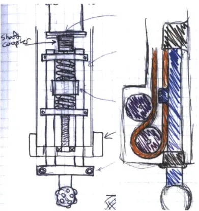
Figure 2-7: Concept drawings for the robot's toe actuators. Lead screw design on the left and cable drive on the right.
of a series elastic element. The series elastic actuator has been a popular robot design element in recent years because it allows force output from actuator that work primarily in position like lead screws. Of more importance here is ability to bring the contact dynamics of interaction with the world outside the robot into the robot's actuator [16]. By making the designed elastic element in the robot joint much more compliant than the ground contact itself the dynamics of the ground contact are brought into the actuator itself. This is a huge advantage because it means the known compliance of the actuator dominates the impact and the hard to model dynamics of the contact can be neglected. It also means that the collision is much more inelastic, much like a car's suspension system is designed to have a small mass on the end of the spring to maintain contact with the road, the toe has a small mass on the end of the spring which means the weight of the robot forces it to stay in contact with the ground.
Because the ground contact force can only ever be applied in one direction (the ground will never pull the foot) only a one-sided series elastic element is required
Figure 2-8: The robot's series elastic foot actuator.
Figure 2-9: The cable which connects to the moving carriage in an inkjet printer was the design inspiration for the similar mechanism in the robot's feet.
which saves a significant amount of room in the mechanism. While the mechanism worked well it turned out to be a bad decision in hindsight because the hard contact on one side means that an inelastic collision is experienced every time the foot force transitions over the spring preload making the dynamics model unnecessarily complex. The picture of one of the feet in Figure 2-8 shows a few key design elements worth discussion. The linear potentiometer which measures the spring compression can be seen parallel to the spring and the ribbon flex cable which connects it to the controller board is the flat white cable connected to it. Getting that cable right was one of the major design challenges of the actuator because the carriage which holds the potentiometer translates a long distance. Either a full cable carriage is required or the cable must somehow constrain itself be planar and fold over itself reliably. The design is borrowed from what is commonly used in inkjet printers which need to solve exactly the same problem with their moving carriage. A flat, stiff ribbon is used which maintains itself in plane but is flexible out of that plane, allowing it to fold over itself as the carriage moves.
The offset motor configuration is important for a reason besides packaging of the actuator, it allows a timing belt to be inserted between the motor output and the lead screw. This is critical because the specific loading and velocity requirements of the foot weren't known at the time of construction, the timing belt allowed the gear ratio be modified very easily to put the actuator's operating range in the right place once
testing established where that was. The same design decision is behind the way the aluminum platens are clamped onto the guide shafts instead of using a more positive locking mechanism, it allows different length springs to be added after the fact and the amount of preload to be easily changed.
Figure 2-10: The two middle feet branching off from the single middle leg. The final main design point on the feet is why there are four of them. The original reason here was that it's simpler to build four of the same actuators than two of the same and one different because it carries twice the loading of the other two. Later on a more important reason emerged, stabilization of side to side motion. Originally the two middle feet were joined back to back but early in testing it became apparent that a larger stance distance was required to keep the robot solidly stable in that direction. This is why the spreading truss pictured is aluminum rather than the titanium sheet construction of the rest of the robot, it was produced after all of the expensive titanium sheet had been used up. With the feet further spaced apart as
Figure 2-11: The original foot configuration where the middle two were bolted back to back.
pictured that motion is no longer a problem.
2.2.2
Body and Bisection Mechanism
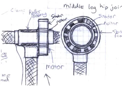
The body itself is probably the simplest part of the robot. Its only job is to hold all of the robot's support systems together in an organized fashion. The main interesting aspect to it is the angle bisecting mechanism whose job it is to keep the angle of the body parallel to a bisector of the inter-leg angle. While it sounds a little complicated, it's surprisingly easy once it's noted that the body is mounted to the frame of the outer leg and the driveshaft for the inner leg is easily accessible. These two can be driven against each other with some drive system and gear ratio to produce any kind of prescribed angle with relation to the two legs. A 2 : 1 drive ratio between the links produces the desired angle bisecting behavior.
As shown in 2-12 this is accomplished with a tensioned cable drive. While this configuation was more difficult to design and assemble than alternatives such as a chain drive the big advantage is that it's possible to completely eliminate backlash
and produce a very smooth drive system.
While the prescribed angle mechanism is straightforward and reliable there are serious advantages to being able to actuate the body against the rest of the robot. The large mass of the robot's support equipment (computer, batteries, etc) makes it a great body to actuate against to assist in regulating the motion of the legs. In addition to this, changing the forward or backward bias of the body while largely keeping it bisecting the inter-leg angle can change the passive dynamics of walking gaits, producing faster and slower walks without the cost of spending energy on another full actuator.
2.2.3
Hip Actuation
The robot's hip actuator, which applies torque between the legs, is easily the most important actuator on the robot as it provides almost all of the regulation during a walking gait. Ideally this actuator would have great bandwidth, zero backlash, unlimited speed, be able to provide more torque than we would ever be able to safely use, and be lightweight. Stepping away from the ideals, we can limit the requirements on speed to what would be reasonable for the leg swinging during a running gait. As for the torque requirements, they were put together with the idea that that robot should be able to easily lift one leg to a right angle, based on the somewhat arbitrary initial weight budget.
Initial concepts were made around using a direct drive actuator at the hip. Direct drive actuators provide the ultimate in bandwidth, torque accuracy, zero backlash, and friction characteristics because they completely forgo gearboxes, using the ele-ments of an electric motor to move the robot's links directly. This means that the passive dynamics of the robot are easy to maintain and manipulate with little energy input. It's possible to mimic the desired passive dynamics with a motor and high ratio gearbox up to some limiting frequency range, but requires a lot of energy to keep the motor following what the passive dynamics want to do. Most robotics work up to this point is focused on completely ignoring the passive dynamics of the system and imposing desired dynamics with some energy efficiency which is what the large
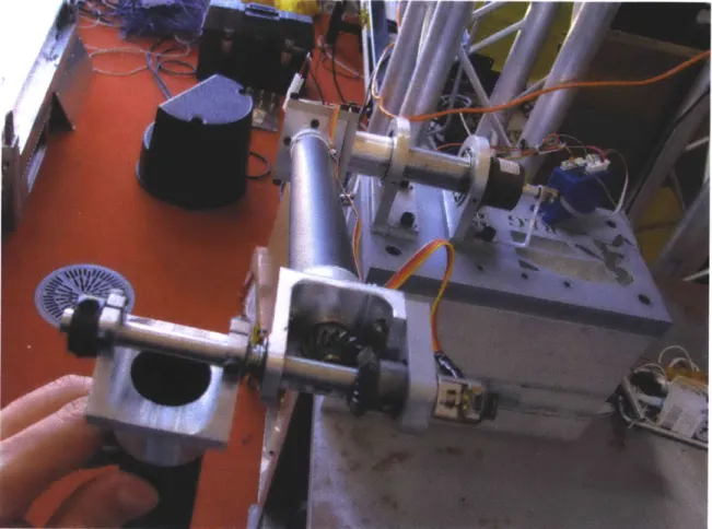
Figure 2-12: The body's angle bisection mechanism.
Figure 2-13: Initial concept for a direct drive hip actuator using a frameless motor and our own aluminum frame. This allows the motor to be built into the robot in the most efficient way possible.
gearboxes traditional to robotics excel at. A full discussion of the topic is available in [1].
The big problem with direct drive actuators is that to get torques in the range
that we require, around 30N - m the actuators get to be unfeasibly large and heavy
because they need a large radius to apply the small electromagnetic forces generated on. Meeting somewhere in the middle on this design issue is difficult because almost all gearboxes have some backlash inherent to them, something that we really wanted to avoid based on past experience with the acrobot. One gearbox that doesn't suffer from backlash is the Harmonic Drive. Typically Harmonic Drive gearboxes are the domain of very high gear ratios and the complete antithesis of a passive dynamic actuator, but with some creativity a very acceptable compromise between direct drive and weight concerns was found.
The operating principles behind the harmonic drive are very different from tra-ditional gearboxes, involving flexible metal gears that deform elastically. The fact that the gears deform elastically into each other means that the input and output are always tightly meshed together. A full explanation of the operating principles, along with a very helpful animation is available from the producer [12]. Normally the Harmonic Drive isn't considered to be backdrivable, the large torques at the output
Wave Generator
Figure 2-14: Explosion of a Harmonic Drive gearbox from the Harmonic Drive oper-ating principles literature [12].
required to break free even the tiny amount of friction at the input would cause the very small teeth on the flex spline to skip and permanently damage the drive. In the case of the lowest gear ratios available however, two things work in favor of backdriv-ability. First is that with a small ratio the friction at the input is multiplied by a much smaller amount (as it would be with any gearbox), but more importantly the teeth inside a low ratio Harmonic Drive are very large. This means that the drive is much more robust to large torques at the output and suffers from less friction internally. The lowest ratio drive of 30 : 1 was selected for this application, opening up a large selection of small, high specific torque motors to use.
Another note of interest about the gearbox used is that it's a fully contained unit including an output bearing. The output bearing is of the cross roller type and is tightly loaded in order to minimize play in the output. This is because the drive is designed for having cantilevered loads applied to it, such as fully supporting a robot arm, but has the unfortunate effect of vastly increasing the amount of friction at the drive output. Initial tests with the gearbox were very disappointing because very large and unpredictable torques were required to break the leg free and very little of the desired passive dynamics were exhibited. Because the robot's leg joint is double support thanks to the bearing opposite the gearbox this bearing doesn't need to be nearly as tight, so the gearbox output bearing was modified by shimming
Figure 2-15: The 30 : 1 ratio Harmonic Drive gearbox used in this robot, showing the very large driving teeth. Overall diameter of the flex spline (right) is about 2.5 inches.
out the bearing races about 0.001 inches. This small change turned the gearbox from disappointing to better than we ever expected, exhibiting very small and very predictable static and viscous friction characteristics.
Figure 2-16: The cross roller bearing inside the robot's Harmonic Drive gearbox. The motor paired with the gearbox is a ThinGap TG2310 brushless, ironless DC motor. This choice is just as notable as the gearbox because the ThinGap motor exhibits the best specific torque characteristics available [21] at moderate speeds and the ironless core means that the motor doesn't exhibit any of the cogging that normal brushless DC motors have. The moderate speed point is important because with the gearbox the motor is no longer moving extremely slowly. These characteristics are
due to a new method of producing the windings from copper sheet rather than wire. This motor paired with the aforementioned gearbox produces a hip actuator capable of exerting over 30N-m of force at high speeds very accurately and without any backlash.
The big disadvantage to the gearbox is that the Haromic Drive introduces a series compliance with the motor. This is due to the thin structure of the flex spline, the part of the gearbox that deforms to make the magic of the device. While this isn't noticeable most of the time, many of control experiments excited the lightly damped (the motor side of the drive system has very little friction) high frequency dynamics that this introduced. This can be handled in software and is discussed in Chapter 3.
2.2.4
Frame
The robot's frame, while the most visible part of the robot, is one of the less important parts of the whole system. It serves mostly to locate all of the important actuators, sensors, and mechanisms in space in a reliable, lightweight manner. Once it's known what goes where and how much force will be applied between these pieces the required structural properties can be determined and fulfilled. Rather than spend a lot of time going over this process, I'd like to mention just a couple important design choices and lessons learned.
The frame is a fabricated sheet metal structure. This decision has more to do with efficiency of resources than performance of the robot. It's much cheaper than cutting the large three dimensional structures from solid pieces of material and we have better equipment for working with sheet metal parts in-house. The waterjet available at the lab allows arbitrarily complex sheet metal parts to be cut with ease and with little material waste. This means that the robot's frame can be prototyped quickly from an expensive high performance material very quickly and at little cost. Besides the waterjet the main enabling resource for this path is access to and skill to use a tungsten inert gas (TIG) process welder. The TIG process allows very high quality welds to be made with almost all structural metals, the main barrier to use being the high manual skill required to perform it.
Following the construction method, the second piece is the material choice. All of the frame pieces besides the legs are made from 6AL-4V titanium for a couple unusual reasons. There are three common materials for structures such as this: steel, aluminum, and titanium. All three materials have similar specific strength (yield strength divided by density) and specific modulus (modulus of elasticity divided by density).
Much of the robot's frame construction is governed by the minimum thickness of material that can be used. Even though a part could be made exceedingly thin according to the predicted loading it's often unwise to do so because the bumps and scratches of everyday use could damage it and sheet thinner than about 0.035 inches thick is difficult to weld by hand reliably. This means a low density material is desired, leaving aluminum and titanium.
The main problem with using aluminum is that it's difficult to produce good quality welds with it in a prototyping situation. The high thermal conductivity of the metal makes it necessary to use very large electric currents to weld it because it draws heat away from the weld site so effectively. When welding the material the portion of the workpiece just on the edge of melting is much larger than with steel or titanium, requiring more manual dexterity to manage the heat input and torch movement.
Titanium on the other hand has thermal characteristics much closer to steel and is very simple to weld except for one very big caveat. The material pulls in atmospheric contaminants very easily at the temperatures involved with welding causing serious embrittlement problems. Special care must be taken to fully shield much more of the workpiece in a pure argon atmosphere than with steel or aluminum which still experience contamination issues, but to a much smaller extent.
The specific titanium alloy used is 6AL-4V, otherwise known as Grade 5. It has a good balance of stiffness and weldability, but more importantly, it's the most commonly used alloy. This means that it's widely available on the surplus market at reasonable prices.
Figure 2-17: The robot's titanium sheet metal hip shortly after being welded. The aluminum fixture was used to hold the three leg connections parallel.
extremely simple geometry-wise. The only thing the legs do is provide a point to point structural connection between the feet and the hip meaning that a mass produced tube can be used in that place without modification. Carbon fiber construction could have been used for the rest of the robot with performance benefits, but the molding and layup process is much, much more difficult and expensive than the sheet metal welding alternative.
Hip Box Analysis
As part of a side project to learn about finite element analysis, the robot hip was subjected to an in-depth analysis after being built with interesting findings worth noting here. The cutouts in the hip box structure that contains the hip actuator were made based on design intuition. The box can be thought of as a simple beam and the triangular cutouts attempt to remove material from the neutral axis where it isn't being used effectively. This should produce a structure that has a better stiffness to weight ratio. In order to find out if this actually happened a simplified model of the hip box was compared to a a model of the same outside dimensions without the cutouts. The box without the cutouts has a weight of 383 grams versus 275 grams
Figure 2-19: The simplified version of the robot's hip box subjected to an end load. with the cutouts.
The analysis was performed using ADINA, a commercial FEA package, with shell elements. The analysis assumed small strains but large displacements. The box is fully fixed at one end and an end load was applied along the top edge of the opposite end. The loading isn't what is actually seen with the robot, but is representative of some of the real loadings when looking at how the overall structure behaves. The primary reason for the simplified loading is to make the simple box model analytically tractable so that the initial FEA results could be checked against a known answer.
Figure 2.2.4 shows the relevant numerical results of the analysis. The stiffness of the simple box remains high and linear up to extremely high loads but the modified box shows much less rigidity initially and the analysis fails at a relatively small load. In both cases the analysis failed because of catastrophic buckling. The initial takeaway message is that the material removal was a bad idea, it actually ruined both the stiffness and strength of the structure for little weight savings.
The exact structural mechanism by which this happened can be seen in the com-parison between Figures 2-20 and 2-19. The simple beam shows a pronounced bulging
Figure 2-20: The hip box without the triangular cutouts under the same loading.
Minimum Displacement vs Force
--4--Simple Box - -- Cut-Out BoxForce (Newtons) O.OOE+00 -1.OOE-04 -2.OOE-04 -3.OE-04 -4.OE-04 -5.OOE-04 -6.OOE-04
downward of the top plate which doesn't happen with the complex beam, what's hap-pening here is the material removal removes the coupling between the box sides and the top. In the case of the simple box the highly loaded bottom part of the sides is held in plane by the section that first order beam intuition suggests isn't doing any-thing useful. When this material is removed the thin sections that should be carrying the load go into buckling almost immediately.
Chapter 3
System Architecture
Besides the base mechanical and electrical design of the robot there is another world of software infrastructure that ties all the individual sensors and actuators together. Previous experimental platforms we had built at the lab used relatively simple soft-ware systems, a master program that communicated will all the onboard sensors and actuators, typically connected via a single data acquisition board.
This kind of setup works halfway decently for robots that have a few similar sen-sors, for example a couple encoders, an IMU, and some motors. All the libraries to work with the different devices can be linked in and threaded together without too much complication. This kind of system often uses a software backend like DSpace, Labview, or Simulink XPC. As a robot grows in complexity the software's respon-sibilities start to bloat and the system becomes more fragile unless failure cases are expected and handled. Along with that bloat, it can be expected that most of the software in a research lab's arsenal will be somewhat buggy and have little in the way of fault tolerance because it was produced by graduate students. Ideally pieces of the robot's system should be able to fail without bringing down any other parts, be easily monitored, and be trivially reusable without knowledge of the underlying code.
It's also often the case that a robot often requires software pieces compatible only with different programming languages and communication between multiple comput-ers. For example, a motion capture arena, the robot's onboard computer, and a controller computer with a user interface. As it's a buggy research platform we'd
![Figure 2-14: Explosion of a Harmonic Drive gearbox from the Harmonic Drive oper- oper-ating principles literature [12].](https://thumb-eu.123doks.com/thumbv2/123doknet/14722539.570769/42.918.229.702.99.362/figure-explosion-harmonic-drive-gearbox-harmonic-principles-literature.webp)