The Determination of Hemocompatibility of a Geometrically-Altered
Poly(dimethylsiloxane) Surface
By
Geoffrey A. Becker
SUBMITTED TO THE DEPARTMENT OF MECHANICAL ENGINEERING IN PARTIAL FULILLMENT OF THE REQUIREMENTS FOR THE DEGREE OF
BACHELOR OF SCIENCE IN MECHANICAL ENGINEERING AT THE
MASSACHUSETTS INSTITUTE OF TECHNOLOGY JUNE 2005
MASSACHUSETTS INS E OF TECHNOLOGY
© 2005 Geoffrey A. Becker. All rights reserved.
N
The author hereby grants to MIT permission to reproduce
LIBRARIE
and to distribute publicly paper and electroniccopies of this thesis document in whole or in part.
Signature of Author: ,
/1 1 rm ent of Mechanical Engineering May 6, 2005 Certified by:
Nam Pyo Suh Ralph E & Eloise F Cross Professor Thesis Supervisor Approved by:
Professor Ernest G. Cravalho Chairman of the Undergraduate Thesis Committee
The Determination of Hemocompatibility of a Geometrically-Altered
Poly(dimethylsiloxane) Surface
By
Geoffrey A. Becker
Submitted to the Department of Mechanical Engineering On May 6, 2005 in Partial Fulfillment of the Requirements for the Degree of Bachelor of Science in
Mechanical Engineering
ABSTRACT
Bio- and hemocompatibility are some of the driving forces behind medical device creation and materials science in this day and age. An experimental study was performed to test whether a geometrically altered surface of Poly(dimethylsiloxane), or PDMS, was found to be more or less hemocompatible than a flat, unaltered film of PDMS. In this case, the alteration was the addition of micron-scale posts sticking perpendicular to the surface, creating a superhydrophobic "bed of nails" effect. Once the specific altered surfaces were chosen, designed using Photolithography, and manufactured via a polymer casting process, a platelet adhesion assay was developed to assess the relative hemocompatibility of the surface via number of platelets counted on the surface of the altered vs. unaltered PDMS. Apparent contact angles of blood and Platelet-Rich Plasma (PRP) on the surface were also measured.
The final instance of this experiment yielded positive results: The geometrically altered surface yielded less debris and platelet adhesion than did the flat PDMS surface, indicating an
improvement in the hemocompatibility of PDMS via this process.
Thesis Supervisor: Nam Pyo Suh
Acknowledgements
The author would first and foremost like to thank AJ Schrauth for his excellent and ingenious work in this project, and for always being there to explain concepts or lend a hand, regardless of his expertise in the area. Also Dr. Alisha Sieminski for her endless patience with two Mechanical Engineers, and thoughtful commentary throughout the process. Professor Suh, for being a wise and patient advisor, always willing to listen to theories and offer his creative mind and expertise. Professor Roger Kamm, for the generous use of his laboratory space and other facilities.
Contents
1. Introduction ... 6
2. Background ... 7
2.1 Improving Biocompatibility- Why is it Useful? ... 7
2.2 Blood Clotting ... 8
2.3 Poly(dimethylsiloxane) ... 9
2.3 Improving a Material's Biocompatibility ... 10
2.4 Capillary and Wetting Theories ... 11
2.5 Wetting Theory's Use in Biological Experimentation ... 13
3. Experimental Section ... 18
3.1 Goal ... 18
3.2 Axiomatic Design of the Blood/Body-Interface Surface of a Biomedical Device ... 18
3.3 Design of the PDMS Surfaces ... 21
3.4 First Experiment ... 21
3.5 Second Experiment ... 25
4. Results ... 27
4.1 First Experiment Results ... 27
4.2 Second Experiment Results ... 29
5. Discussion ... 33
5.1 Review/Analysis of Results ... 33
5.2 Future Studies ... 35
5.3 Applications/Extensions of this Design ... 36
Figures List
1. Clotting and Coagulation Cascade ... 9
2. Geometric Breakdown of Rough Wetting ... 12
3. SEM image of SU-8 structure (=0.04) viewed 30° from normal ... 14
4. SEM image of nanoporous aluminum oxide ... 15
5. Master Design Matrix of the Biocompatible Surface ... 20
6. PDMS-housing apparatus for Experiment 1 ... 22
7. Blood After Centrifugation ... 23
8. Control PDMS at 1,400x ... 27 9. s = 0.16 at 1,400x ... 28 10. s = 0.04 at 1,400x ... 29 11. Control PDMS at 1,400x ... 30 12. s = 0.04 at 1,400x ... 30 13. = 0.04 at 1,400x ... 31 14. Flat PDMS vs. s = 0.04 ... 32 15. 5 L blood on s = 0.04 ... 32 16. 5 L blood on s = 0.08 ... 32 17. 5tL blood on s = 0.12 ... 32 18. 5gL blood on s = 0.16 ... 32 19. 5gL blood on s = 0.12 ... 32
1 Introduction
Biocompatibility has been the buzzword of the year since implantable medical devices began coming out. To have a biocompatible device is to have a profitable device. Even devices that are non-implantable, but only need to be inside the patient during a surgery perhaps, still must be somewhat biocompatible. In implantable devices especially, hemocompatibility, or blood compatibility, is an extremely important aspect of biocompatibility.
A very large portion of the research done to date on finding newer, more hemocompatible materials and then adding chemical surface characteristics to those materials to make them even more biocompatible. This researcher and the graduate student he worked with, AJ Schrauth, went down a different path toward improving the hemocompatibility of a material. Using nature's example of the lotus leaf, we opted to geometrically alter the surface of a hydrophobic material, Poly(dimethylsiloxane) to make it superhydrophobic, in hopes that this would improve its hemocompatibility. The advantage of such a design is that it would require nothing but a simple casting rather than a series of complex, often expensive chemical processes.
2 Background
2.1 Improving Biocompatibility- Why is it Useful?
Biocompatibility is usually considered a measurable property of a material; specifically, the extent to which the material's interact with the body does not produce a toxic, harmful, or type of immune response in the body. Any material can undergo a variety of tests to determine its biocompatibility in regard to certain tissues of a specific species. As one might suspect, these experiments determine interactions between the tissues, blood, etc, and the surface of the material in question. Blood, in fact, is one of the main telltales of biocompatibility, as blood contains numerous constituents of the immune system, such as platelets, antibodies, T cells, and macrophages (among others). This aspect of biocompatibility is known as hemocompatibility, or compatibility between a foreign surface/substance and active (living) blood.
The typical first sign of an insufficiently hemocompatible material is thrombus (clot) formation 2-7. Thrombi are very dangerous in that, although the clot forms as an attempt to protect
the body from the foreign substance (i.e. the biomaterial), it often obstructs the flow of blood in the vessel or whatever the vicinity of the material. This can lead to damage in the area due to insufficient blood/oxygen supply, or worse, the thrombus could break off and migrate into the heart (causing myocardial infarction) or the brain (causing stroke) or other areas of the body. Therefore, in the present, if a biomaterial is to come into transient contact with active blood, heparin, a standard anti-coagulant, is injected into the body to avoid thrombus formation8. While this is generally sufficient, there are certain problems associated with heparin and other
anticoagulants like it- some patients may have an adverse reaction to it (from erythema to ulceration to vomiting to less serious discomforts), and hemorrhaging is a serious and fairly
common concern . common concern
2.2 Blood Clotting
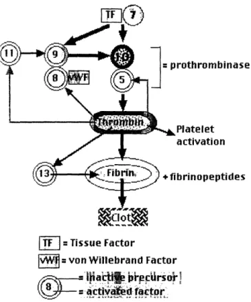
Blood clotting exists to stop loss of blood following an injury in which vessels, organs, and tissues are broken or damaged. The clot itself is a grouping of platelets intertwined with a network of fibrin molecules. When a break in a vessel occurs, the cells of that vessel display a surface protein (see Figure 1) Tissue Factor (TF), which binds to an activated Factor 7. This heterodimer then cleaves two other proteins called Factor 10 and Factor 9. Factor 10 then binds to Factor 5, which then converts prothrombin (Factor 2) into thrombin. Thrombin then cleaves fibrinogen to create fibrin, and activates Factor 13 to make the fibrin molecules "sticky" with respect to one another, creating the fibrin network.
Meanwhile, Factor 9 (cleaved by the TF-Factor 7 heterodimer) becomes activated and binds Factor 8 and the von Willebrand Factor (vWF). This heterotrimer complex activates more Factor 10, amplifying the process. Thrombin generation activates more of Factors 5, 8, and 11,
which activate more Factor 9. Additionally, the vWF binds the platelets to the exposed collagen from the torn/damaged vessel. The presence of thrombin and collagen activates the platelets. When the platelets are activated, they release thrombospondins, which activate other platelets and aid in "stickiness". The platelets also alter their shape to accommodate "plug formation" 1 .
rothrombinase
Platelet
activation
ibrinopeptides
IT- = Tissue Factor
v= on Willebrand Factor
a~ct
oto'.r
Figure 1: Clotting and Coagulation Cascade
2.3 Poly(dimethylsiloxane)
Poly(dimethylsiloxane), hereafter referred to as PDMS, is a widely-used silicone rubber. As part of the Silicone family, it has the characteristic Si-O backbone. Specifically, PDMS is comprised of a repeating (CH3)2SiO unit. PDMS is made via a reaction called "direct process",
in which silicon and methyl chloride are combined, distilled, and then hydrolyzed to produce the final product'2. PDMS is a useful material because of its high heat stability, high gas
permeability, transparency, fair hydrophobicity, and decent biocompatibility. Because of its hydrophobicity and other surface properties, PDMS is often used as a coating to make a surface
more biocompatible. Much of this thesis will be devoted to the explanation of how the hydrophobicity of PDMS was improved in order to improve its biocompatibility.
In 1984, PDMS was recommended by the National Heart, Lung, and Blood Institute to be examined as a potential hemocompatible material to be used in vivo and in vitro in biological settings. In order to assess the degree of hemocompatibility, a variety of tests were run on PDMS. These tests were also run on Low-density polyethylene (which has been a standard biomaterial for some time), and comparisons were run13.
To determine the biocompatibility of each material, the NHLBI observed the materials' surface interactions with blood cells. Platelet uptake, one of the key triggers of the immune reaction and thrombus formation , was found to be lower in PDMS and LDPE than many other materials in question (implying a stronger hemocompatibility).
One area in which PDMS seemed to be behind LDPE and some other materials, was in what is called "acute ex vivo platelet deposition experiments" 5, in which blood was merely deposited on the material surface, left to sit for an hour, then washed off and remaining adhered platelets counted. The in vivo equivalent to this is a situation in which blood pools to a large extent, either due to poor circulation, a bruise/other type of swelling, etc. So in order for PDMS increase its standing against LDPE, HDPE, and other recognized hemocompatible materials, it needs to show improved results in experiments like acute ex vivo platelet deposition. This need
16,17 was also affirmed in other scientific papers as well6 7. 2.4 Improving a Material's Biocompatibility:
It should be clear from the above section that improving a material's bio- or
hemocompatibility would be valuable for the future of the material in biomedical and other applications. There are a few tried and true ways to improve a material's biocompatibility. The
simplest of these is to coat the material with another, more biocompatible material or graft on hydrogels or hydrophobic alkyl chains to the material. However, as we are trying to use PDMS
as that more biocompatible material in the first place, this would not be of much help. There are also a variety of things that can be done to the material's surface that will improve its
biocompatibility. Many of these are chemical changes, which in essence alter the surface's molecular structure, in many cases making it more hemocompatible. For instance, it was found that alpha-allyl glucoside used for surface modification of Poly methyl methacrylate (PMMA) via plasma-induced in situ polymerization improved the biocompatibility of an intra-ocular lens made of PMMA8.
Another method, however, involves increasing the hydrophobicity of the already-hydrophobic material via a geometric rather than chemical change in the material's surface. A natural example of this phenomenon is observed on the surfaces of lotus (Nelumbo nucifera) leaves19. The leaves exhibit small (nanoscale) bumps on them, which dramatically increase the hydrophobicity of the leaves. More importantly, their presence significantly reduces the tendency of fouling, as any particle of dirt, etc which lands on the lotus leaf is in contact only with the tops of said bumps. Therefore, when a droplet of water rolls down the leaf (and over the location of the debris), the debris will more likely stick to the water and roll off the leaf, keeping it clean. This phenomenon is known as the Lotus effect, and was one of the major inspirations for this project.
2.5 Capillary and Wetting Theories
The design behind this relates to capillary theory and wetting theory. J.W. Gibbs20 determined that surface interactions are a smooth, rather than sharp, transition between two
materials. However, thermodynamically, there is a discontinuous jump between any two surfaces, resulting in a surface tension value, y, where
j)(A (A)
y- -U , where U(A) represents the internal energy of the surface interaction, and A is the area
dA'
of the surface interaction (other related surface variables are held constant). Note that this value is calculated for the interaction of two surfaces, not a single surface itself, and that surface tension is therefore a property of the interaction of the surfaces. As surface tension can be related to a "force", ydA approximates the work required to change the surface area. Another useful
equation is Laplace's Equation of Capillarity, AP = + +. , where R1 and R2 are the radii R 2
of curvature of the droplet. As R2approaches o (i.e. approximating in 2 dimensions for mathematical simplicity), one begins working with a scenario similar to that seen in FIG
Figure 2: Geometric Breakdown of Rough Wetting
Using this model, and substituting
2. cos(t6)
one ets he euatin AP-2. Yt'cos(O)
one gets the equation A - , so the liquid pressure that can be held by posts w w
apart and with surface tension y and contact angle 0 will come to be AP.
Contact angle is a rough way of measuring the attraction between a liquid and a solid: if a droplet of the liquid is attracted to the solid surface, the droplet will spread out on the surface, maximizing the area of interaction (such as water on a hydrophilic surface) and displaying "complete wetting". As measured with a protractor, this would constitute a small contact angle. On the other end of the spectrum, if the droplet is not attracted to the surface, the droplet will ball up, minimizing the area of interaction (such as water on an oily, hydrophobic surface), and displaying "composite wetting". This instance would show a large contact angle. With surfaces that are not smooth (as are most surfaces in the real world), another theory applies-Wenzel2l defined "rough wetting theory", in which, due to the complete wetting of the rough surface, there is a larger surface interaction than if the surface were smooth. Wenzel defined a "'roughness" parameter r, which equates to the ratio of the actual surface interaction area to the apparent surface area (i.e. what the area would be if the surface was smooth).
2.6 Wetting Theory's Use in Biological Experimentation
Only in the last few years has any of this theory been applied in a biological setting. In 2002, Khorasani and Mirzadeh8 performed an experiment in which they irradiated a PDMS surface with a CO2 laser. They then ran a wettability test (in comparison to virgin PDMS) and found that, while a droplet of water placed on unmodified PDMS has a contact angle of around 105°, their laser-pulsed PDMS exhibited contact angles up to 170°, i.e. their laser-pulsed surface was superhydrophobic. They also showed significantly improved hemocompatibility, tested via platelet adhesion. Whereas the virgin PDMS showed relatively high platelet adhesion, and the formation of microthrombi, the laser-treated PDMS showed very little adhesion and almost no
activation. In addition to the possibility of chemical interaction aiding in this hemocompatibility increase (the laser partially altered the chemical surface structure of the PDMS), they cited both the surface roughness and the possibility of air pockets created by the pulses as among the potential causes for the superhydrophobicity. They were able to measure the approximate size of their pores, which was around 400nm. Despite their lack of information regarding how wetting theory specifically played a role in the superhydrophobicity they obtained, it is believed that the geometry of their surface did play a role (possibly a significant role).
Recently, AJ Schrauth, a graduate student at MIT, has begun working on a PDMS design created to produce results similar to the lotus effect. This design differs from Khorasani's and many others in that, rather than rely heavily on the chemical interactions between the surface and a liquid, its additional hydrophobicity is completely due to geometric modifications of the
surface. In adherence with wetting theory, Schrauth designed a surface with small posts
protruding perpendicular to the surface. An iteration of the final result of this design can be seen in Figure 3, in which posts are 20gm across, and have 50gm between them.
Figure 3: SEM image of SU-8 structure (s=0.04)
The PDMS used by Schrauth and this researcher, Sylgard 184 (Dow-Coming, Midland, MI) is made via low-temperature casting. The polymer base and the curing agent are kept separate until one is ready to cast. The two are then mixed together in an approximately 10:1
ratio, and air bubbles created in the mixing process are removed. The surface one wishes to cast must be thoroughly cleaned with ethanol or isopropanol, then dried with nitrogen. The surface is then coated with a releasing agent called Trichlorosilane (Gelest Inc.,Morrisville, PA), and finally the liquid PDMS mixture is poured onto the surface, and the entire apparatus is placed in a vacuum (to ensure that the PDMS fills in even the most complex surface details of the original surface, and to remove air bubbles that might be trapped between the PDMS and the surface). Once this is ensured, one places the apparatus in an oven to bake for two hours at 90° C. The dried PDMS can then be carefully peeled off its mold, and used as a silicone rubber.
While the manufacturing of the PDMS is fairly trivial, the manufacturing of these micron-scale structures (i.e. finding/creating a suitable mold) posed the real challenge. Schrauth tried a variety of techniques, with the author's research fueling some of them. Among the ideas
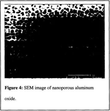
Figure 4: SEM image of nanoporous aluminum
was the anodizing of aluminum to make nanoscale pores in the surface of the metal as seen in Figure 4. Such honeycomb appearances are formed when aluminum is oxidized in the presence of strong acids such as sulfuric acid. This could then be used as the mold for the PDMS, creating
very small (200nm diameter) posts separated by only 25nm or so. Information regarding the adjustment of pore size and inter-pore distance was also found.2 2However, successful casting of the PDMS from the nanoporous alumina proved exceedingly difficult. In many cases, the pores were so small that the detail in the alumina was not found in the PDMS cast; additionally, many attempts to peel the PDMS off of the mold caused the aluminum to fracture, prohibiting a clean
separation.
Other mold trials involved wire and polymer meshes, fishing line, a brief look into woven fabrics and waterproofed outerwear. Among the problems found with these trials were incorrect ratios between the post size and inter-post area, and PDMS leaking through to the other side of
the materials, creating non-uniform posts. Further things looked into by Schrauth and this
researcher were the use of ordered DNA strands, Carbon nanotubes, and self-assembling peptide structures. However, given the resources and time required to adequately create these structures, the ideas were discarded. Photolithography (a rather complex technique also used to manufacture computer chips and other detailed nano- and micro-scale surfaces) is very precise, highly
controllable/flexible, and (with electron-beam lithography) can cut features as small as 5nm23.
Unfortunately, lithography is a very slow and expensive process, as one needs to have masks made, perform a time-costly setup of the system, and then, in very sterile conditions, run the exposure. With photolithography, there are two options available as molds: 1) etching the silicon itself, so it is the actual mold, or 2) using the photoresist placed on the silicon. Photoresists come as positive or negative resists. Positive resists harden everywhere there isn't UV light. In other
words, if we wished to use a positive resist, there would have been a high ratio of exposed resist to covered/unexposed resist. In practice, this is encumbering, as, the more exposure area there is,
the harder the process is to control. With a negative resist, the hardening takes place everywhere there is light. The problems associated with etching the silicon generally involve additional time, and the silicon wafers are relatively thin, and somewhat brittle. The problems with using the photoresist as the mold is that the photoresist is not overly robust, so would have to be recreated frequently (which is time-consuming and expensive). In other words, while lithography is a very useful technique, it is not ideal for large-scale manufacturing or for larger-area surfaces when avoidable.
Schrauth eventually took advantage of the fact that PDMS can be cast against itself, with cured PDMS acting as the mold. With this possibility, one only has to perform the
photolithography process once (making a the end-image in the photoresist), casting PDMS to that photoresist image (creating the negative of the image), and then repeatedly casting PDMS off of that negative image. Since PDMS is quite robust (it is not brittle, and can maintain highly detailed features after extensive use), the negative PDMS cast will solve the problems created with repeated casting of the silicon wafer or the photoresist.
Schrauth settled on a negative resist, SU-8 2000 (Microchem, Newton, MA). The image to be formed from the photoresist is a positive one (i.e. posts sticking out rather than holes where posts would be). It is good practice to use as little area exposure as possible, since large exposure area could lead to over- or under-exposure, and therefore decrease the accuracy of the process. Since the posts themselves occupy, in every case, less than 16% of the total area of the section, it makes the most sense to use a negative resist.
3 Experimental Section
3.1 Goal
The goal of the following experiments is of course to test the effectiveness of the above
geometric surface modifications in improving the hemocompatibility of PDMS as opposed to a flat PDMS surface. Therefore, PDMS test surfaces of varying specifications and a protocol under which to run the experiment were designed and created.
3.2 Axiomatic Design30 of the Blood/Body-Interface Surface of a Biomedical Device
The most basic Functional Requirement for the surface of a biomedical device is to: FRO: Aid the device in its purpose
DP0: Surface which aids/does not inhibit the device performing correctly
When this is further decomposed, we see slightly more specific functional requirements, FR1 and FR2:
FR 1: Assist/do not inhibit the device in performing its specific function FR2: Ensure that the body's immune system does not attack device
Here, FR1 refers to the specific function of the device, and requires the surface not to interfere with that function. FR2 (the focus of this project) requires that the device, to as large a degree as possible, prevent the device from activating the cascade of immunological responses the body uses to detect and remove foreign objects. One major step of these responses is coagulation, which, as mentioned in the background, is generally useful, but will likely inhibit the device's function (violating FR1) and can be dangerous to the body itself. Also, a constraint (C1) must be added in: that the material be non-toxic to the cells and other functions of the body. Therefore:
DP2: Hemocompatible surface
Since FR1 is specific to the individual device, this author will focus on expanding DP2: FR21: Lower the inclination for clotting to occur in the event of factor-surface interface
FR22: Lower the amount of physical surface interaction, which leads to large-scale thrombosis FR21 refers to the ability to, once a clotting factor has reached the surface and touched it, prevent it from activating the rest of the immune system cascade. FR22 refers to making it as difficult as possible for that clotting factor to reach and touch the surface in the first place. These two requirements led to the following DPs:
DP21: surface which releases (or is coated with) an anticoagulant of sorts, to antagonize the clotting process.
DP22: "bed of nails" structure to limit the amount of surface-factor interaction.
Since chemical anticoagulants are not the focus of this project, DP21 will not be further expanded. However, in order to adequately adhere to DP22 without actually increasing the possible contact area between the surface and clotting factors, another constraint (C2) must be added: the material constituting the geometric structure must be hydrophobic. With this in mind, DP22 expands to:
FR221: Must support blood pressure, with blood as the "composite wetter" (see Background) FR222: Must lower the contact area as compared to a flat surface
As shown in the Background section, the amount of pressure a rough surface can hold depends on the material, and percentage of actual surface area as compared to apparent surface area. Therefore:
I)P221: Surface with small spaces between posts to achieve higher-pressure capabilities. I)P222: Smaller posts to maintain a respectable ratio of (post-size):(area between posts).
From here, a master design matrix is created, illustrating the Functional Requirements and how they are handled by the Design Parameters.
FR1 FR21 FR2 FR221
FR22FR222
FR2 R22FR222 DP1 X 0 0 0 DP21 0 X 0 0 DP2 DP22 DP221 0 0 X X DP222 0 0 0 XFigure 5: Master Design Matrix of the Biocompatible Surface
More specifically, the matrix displays the interactions between the functional requirements and design parameters, as various DPs influence FRs they were not originally intended for. For instance, in this matrix, DP221 (decreasing space between posts) not only handles FR221 (must support the correct range of blood pressures) as it is meant to, but also affects FR222 (Must lower the contact area). The reasoning behind this is as follows:
If the blood pressure (relative to outside pressure) in FR221 is zIP and the required area ratio (percent of previous area) in FR222 is s, the space between the posts w and the critical dimension of the posts d, then (as can be seen in the Background) the pressure that a given arrangement of posts can support is given by the following equation:
2
-/iv' cos(O) w
FR221 is therefore a function of the space between the posts (DP221) only, so there should be no interaction between DP222 and FR221. From geometry, the area reduction, Os, delivered by a surface with square posts is
From the above equations, FR222 is a function of both DP221 and DP222 and therefore there will be an interaction between DP221 and FR222.
3.3 Design of the PDMS Surfaces
Photomasks (Advanced Reproductions, North Andover, MA) were designed by Schrauth for the experiments. Mask A has four 1-inch square patterns of 20gm-long square holes; the period for the four patterns is 100, 70.7, 57.7, and 50gm respectively. Mask B has two patterns
of 15gm holes (with periods of 75gm and 37.5gm respectively), and two patterns of 25gm holes (with periods of 125gm and 62.5gm respectively). From these, photolithography was conducted, yielding two types of PDMS pattern sets- 1 from mask A, another from mask B. In the
experiments themselves, while all mask patterns were used in observing the apparent contact angle of water, only Mask A was used for the actual blood experiments. The different patterns created from Mask A will hereafter be referred to by their (post area):(area between posts) ratio, or U. For mask A PDMS, this translates to s = 0.04, 0.08, 0.12, and 0.16 respectively.
3.4 First Experiment
Once the PDMS was created, a protocol was designed to accurately determine the degree of hemocompatibility. Apparatuses made of LDPE created on a water-jet were designed and built (see Figure 6) for the purpose of accurately placing the blood on the PDMS surfaces. These apparatuses consisted of a base with a well on one side to receive the PDMS, a series of spacers (for use if the researchers wished to increase/alter the volume of blood placed on the PDMS), and a clear top cover made of polycarbonate. The top cover connected to tubes that connected to a pipette or syringe, so the blood can be drawn up into the pipette, and injected evenly onto the four altered surfaces of the PDMS piece. Each spacer had four holes positioned so the blood would leak through the holes and onto the correct square of the PDMS. Additionally, the top had
extra holes to relieve the air pressure that was likely to build up as the blood was pushed into the apparatus. These pieces were held together by four nuts and bolts, one in each corner of the device.
Figure 6: PDMS-housing apparatus for Experiment 1
In order to develop a protocol that would assess hemocompatibility, the author looked to other studies8 and consulted with Alisha Sieminksi, a Post-Doctoral Fellow who had experience in platelet adhesion tests. The first step of the designed protocol was blood collection. A blood lab (part of the Medical Facilities of the University) took 45mL of blood from the arm of a healthy male in his 20s. They were received in 5mL vials. Prior to being filled with blood, the vials were preloaded with 5% Sodium Citrate. This was done to avoid premature or overly strong coagulation of the blood in the vial, while at the same time not altering any of the platelet
activity. Once the blood was drawn, there exists a four-hour window in which platelet activity is still at an acceptable level for testing. Once the vials arrived, they were placed inside a sterile hood, and the blood was transferred into centrifuge epindorphs, which were then capped and placed in a small centrifuge. They were then centrifuged at 1000rpm for 10 minutes at room
temperature. The centrifugation separated the blood based on density of the particles within it. In the case of the blood, which contains a very wide variety of particles, much of the debris found in blood, cellular material (including red blood cells, or erythrocytes, among others), and most other large objects in the bloodstream dropped down to the bottom of the epindorph tube. This fraction is known as the hematocrit. Above that (due to a slightly lower density) was a thin layer
24 of white blood cells, or leukocytes, known as the "buffy coat", as seen in Figure 72 .
I L
-Plasma
_White blood cells,
the "buffy coat" -Red blood cells
Figure 7: Blood after centrifugation
The layer above that was comprised of the least dense of the materials in the blood, namely platelets, other small particles such as peptides, some enzymes, and of course, the transparent blood plasma. A more complete centrifugation (either at higher rotations or for a longer time) would have yielded approximately 45% hematocrit, 5% buffy coat, and 50% plasma region. However, in this case the only region of interest was the platelet-rich plasma, or PRP. Had there not been significant time constraints (4 hours until platelet activation effectively ceases), there might have been some merit in achieving such percentages. However, further
8
centrifugation merely adds platelet-poor plasma (or PPP) to the plasma region8. Therefore the experimenter decided it was unnecessary to re-centrifuge or centrifuge for a longer period of time.
Once centrifugation was complete, the PRP was pipetted out of each epindorph tube, and into a test tube. A sample of the PRP was then drawn out via pipette, and placed in a
hemocytometer. This device is little more than a carefully-etched microscope slide which defines a series of gridlines, allowing for easy counting of various particles. In this case, the particles to
be counted were platelets. As per the instructions from the hemocytometer, the platelets were counted, and the various dimensional analyses performed. From there, the platelet count was
adjusted to a standard 150,000 platelets per mm3. While this number is rather lower than the unadjusted number counted, its purpose is more to ensure that every blood sample will include at
least this number of platelets. Of course, the adjustment process is useful since, if counting platelets afterwards without a comparison (say, one wants to compare to another study in which platelet count was also performed), one can adjust the platelet count to that of the comparator's count, and directly compare post-experimental numbers. The adjustment itself was done by
diluting all of the PRP with the correct amount of Calcium-containing Phosphate-Buffered Saline, or PBS. It was decided to use Calcium-containing PBS over Calcium-free PBS because a number of the complement activation processes, including platelet activation and binding, require Calcium. The reasoning here was that raising the amount of Calcium in the solution would not alter the binding properties of the platelets (as Calcium would not be the limiting reagent in the reaction); however, had Calcium-free PBS been used, it might have lowered the binding potential of the platelets, causing an altered eventual platelet count. The amount of PBS used was determined using an equation governing the dissolution of a soluble suspension. This combined solution was then vortexed to ensure thorough mixing.
From there, 4mL of the solution was drawn into a lOmL syringe, and the syringe tip (no needle was required for any aspect of the experiment) was attached to the tubes that were connected to the top of the apparatus. From that point, the PRP in the syringe was pushed through the tubes and into the well of the apparatus, until it was visually obvious that all aspects
of the 4 squares of the Mask A PDMS were sufficiently covered in PRP. This process was
repeated for another identical apparatus, which housed the control piece of PDMS (flat, unaltered surface). Both of the apparatuses were then placed on a Pyrex dish, and placed in an incubator at 37.2" C for one hour. This was done to allow platelet activation and spreading to occur against the PDMS surface, simulating the aforementioned acute ex vivo platelet deposition.
After an hour, the apparatuses were removed from the incubator, and disassembled to remove the two pieces of PDMS. The PDMS samples were then vigorously washed in more PBS to remove any non-bound platelets and other debris from their surfaces. A solution of 2.5% gluteraldehyde in PBS was created in order to fix the bound platelets to the PDMS surface for later SEM viewing. This was generously applied to the surfaces of the PDMS samples, and allowed to dry (and fix) for approximately 24 hours. As glutaraldehyde is fairly toxic, it was especially important to perform this procedure in the chemical hood. After 24 hours, the solution was dehydrated using 70% ethanol, and dried. The PDMS samples were then cut into smaller pieces with razor blades, sputter-coated with 150A of gold, and images were taken using a Scanning Electron Microscope using 5kV as the accelerating voltage.
3.5 Second Experiment
A second experiment was later run to reassess the use of the apparatuses in testing hemocompatibility. This experiment ran much the same as the first, in terms of protocol. However, in this experiment, the apparatuses were not used. Instead, after the platelet concentration of the PRP was adjusted using the hemocytometer, a 5pL droplet of PRP was placed on each of the four squares. To ensure knowledge of the location of the droplets on the square, a small area was marked off on the opposite side (bottom) of all PDMS samples to narrow the area to search. Additionally, a 5gL droplet of whole blood was also placed on PDMS
samples in an effort to qualitatively observe how whole blood and PRP act differently on the altered PDMS surface.
While these samples were incubating, a camera and optical lens were set up to observe the apparent contact angles of both the PRP and whole blood. In all previous experiments, Schrauth had only used water as his droplets, so actual measurement of the apparent contact angle was quite novel. These droplets were placed on each of the surfaces (s = 0.04, 0.08, 0.12, and 0.16) and images of them were taken. As with the initial experiment, the incubated samples were then removed, fixed with glutaraldehyde, and then dehydrated and viewed using the SEM.
4 Results Section
4.1 First experiment results
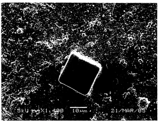
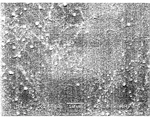
The results of the first experiment were somewhat inconclusive. Typical images of the control piece of PDMS (Figure 8) and the experimental PDMS (Figure 9) are shown below.
Figure 9: Os = 0.16 at 1,400x
In the control sample it is fairly easy to see the platelets- they are the small dots scattered on the surface of the PDMS. On the other picture (Figure 9), however, the platelets are more difficult to see, as there is cellular debris covering much of the bottom of the altered PDMS. As the posts were moved farther apart, as in s = 0.04 (seen below in Figure 10), the extent of debris lessened.
Figure 10: s = 0.04 at 1,400x
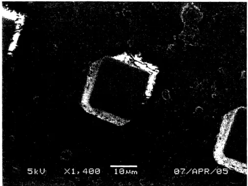
4.2 Second Experiment results
The second experiment showed cleaner results than the first- the control sample of PDMS had approximately the same numbers of bound platelets as in the first experiment, as seen below in Figure 11. In the experimental piece, however, demonstrated a dramatic reduction in debris and platelet count. As before, the ¢s= 0.04 (Figure 12) square had better, cleaner results than did the s = 0.12 (Figure 13) or 0.16; however, all were dramatically cleaner and showed
Figure 11: Control PDMS at 1,400x
Figure 13: Os = 0.12 at 1,400x
The second experiment's results also illustrated cleaner tops of the posts (the parts that actually contacted the droplets) than in the first experiment. The sides of the posts also showed less debris attached.
The additional observations in apparent contact angle displayed as follows. Figure 14 shows the comparison between a 5gL droplet of water on flat PDMS next to a 5PLL droplet of water on the s = 0.04, as taken by Schrauth. Figures 15, 16, 17, and 18 show whole blood on
Figure 14: Flat PDMS vs. Os = 0.04 Figure 16: 5pL blood on s = 0.08 Figure 18: 5LL blood on = 0.16 Figure 17: 511L blood on s = 0.12 Figure 19: 5gL PRP on Os = 0.12 -,-- gig;g
t-
I -g ,, = ..;,- .#i - 'I - I.- -. -- -- -"--i . 1. 1. " I I i I ,-:', I i. . I" . . I,, , 4 . Figure 15: 5VL blood on Os = 0045 Discussion
5.1 Review/Analysis of Results:
With debris appearing both atop the posts and significantly on the sides of the post and the base below the posts, it is apparent that full wetting occurred in the majority of instance here. These results were highly disconcerting until Schrauth and the author ascertained what had
happened. As shown in capillary theory, the downward pressure exerted by the weight of the liquid cannot exceed the surface tension created by the liquid against the posts, as defined by the Bond number of the fluid. One possibility is that, because the apparatuses were enclosed, there may have been too much PRP in the chamber (as it was being pressurized in via the syringe), causing a reversal of the suspension effect and creating full wetting.
Another possibility (this one more likely) is that, since there was no control over whether the PRP spilled off of the altered squares (in fact, it very likely happened given that the original goal was to cover the entire base of the PDMS sample), the PRP that went on the interface between flat PDMS and the altered squares dramatically increased the chance of wetting. It could do this by effectively "pulling" the suspended PRP on the altered squares (via cohesion) down, and going through the sides of the posts (which defeats the entire concept behind the posts in the first place).
Another likely reason for this failure is the material of the apparatus itself. LDPE is a relatively hydrophilic material, so water and PRP will wet its surface fairly easily. When the apparatus was closed (via the nuts being tightened on the bolts) the spacers in the apparatus pressed down on the altered squares of the PDMS sample, allowing the PRP which was flowing down along the LDPE to come in from the side and (because of the deformation of the posts) more easily wet the PDMS fully.
For that reason, the apparatus was not used for the second experiment, and drops were manually placed on the squares; this seemed to improve the resistance to platelet adhesion, as well as the amount of debris found, especially on top of the posts. This would imply that the experimental surface is more hemocompatible than a typical flat PDMS surface. The first experiment actually may serve as proof that the increased contact area between the PRP and the posts (due to the PRP along the side and flowing on the deformed posts) creates more debris, both on the tops of the posts and on the sides, as well as higher platelet adhesion.
One thing left to discuss is the presence of debris beneath the posts in the first place. One possibility is simply that dirt and other debris was able to get in the space between the posts before the actual experiment began. The PDMS samples are difficult to clean down there, given the hydrophobicity and size scale. The other possibility is that the debris comes completely from the blood itself. If this is the case, the question is, how did they get there?
Two theories have so far been put forth. The first revolves around the data that show (in the second experiment) very little platelet adhesion (and debris) on top of the posts, and
noticeably more where there were no posts. This could occur because there is some preference in the complement system for binding to air as opposed to the PDMS. From a logical standpoint, this makes sense, as the drying would occur faster (there is some air flow, and generally there is a gas vs. a solid). Additionally, this makes sense from an evolutionary standpoint- the animal who can close its wounds faster to prevent blood from exiting the body will survive over an animal whose platelets would rather bind to the object it has impaled itself on, starting the long process of breaking down the object itself. Additionally, since PDMS is fairly hemocompatible to begin with (as compared to say, open air), and there is relatively little PDMS available in comparison to air (below 16%, as demonstrated by s), clotting most likely tends to occur most
frequently when the platelets/PRP is in contact with air. Decreasing the size scale from the 10s of microns by around an order of magnitude should eliminate the possibility of such debris falling
in between posts at all, and merely being washed off in the same fashion as fouling on the lotus leaf.
The second theory somewhat incorporates the first, and adds to it the concept of
25
undulating surfaces to reduce friction25. As two surfaces interact, they effectively rub off on each other, and micro-particles of debris are formed. This debris, which remains in between the surfaces, greatly increases the friction between the surfaces. However, if the surface is altered so that it undulates (there are alternating plateaus and valleys) these micro-particles will be created, and then be dumped into the valleys, which effectively act as a waste disposal bin, cleansing the surface (the plateaus only) of particles. It is possible, therefore, that a similar phenomenon is occurring here, between the PDMS-PRP interface, with the spaces between the posts acting as valleys, or waste reservoirs for the clotting particles. When washing occurs, these particles roll off the tops of the posts and into the space between the posts, keeping the "surface" (the tops of the posts) quite clean.
5.2 Future Studies
In future studies of this concept, it could be useful to attempt a smaller size scale of posts (while maintaining the ¢s). This process could use electron-beam lithography or perhaps another tool to further scale down the post size to a micron or perhaps 0ls of nanometers. This change may (partially) eliminate the problem of platelets and other micron-size debris so easily falling in the space between the posts, if it is determined that the space should not be used as a waste reservoir.
Additionally, this project was meant to be more proof-of-concept than a full-out study to determine exactly how hemocompatible our surface is (there is not particularly such a rating, but
referring more to a careful comparison against other materials). Hence, the experiments were smaller-scale: only one sample piece of PDMS was used, which did not allow for sample or experimental error, the experiment was not replicated ad infinitum, so only qualitative
conclusions can be drawn. Additionally, the platelets themselves could be actually counted, via a rather complex process involving the Lactate Dehydrogenase method of platelet counting2 6 27,
training on a UV spectrometer, and obtaining other platelet samples for comparison. This researcher has reason to believe the results shown here will extrapolate to experimentation with flowing blood as well, as it was found that in typical PDMS, high flow rates led to less platelet aggregation than low flow rates and no flow3, so there is little reason to believe that higher flow rates on the altered surface will contain even fewer platelets. However, it would of course be best to actually run high-flow and low-flow experiments to determine the validity of this assumption. In the same vein, running a series of chronic (24 hours of blood/PRP sitting) ex vivo experiments to discover how this surface fairs for longer periods of time would be useful as well.
5.3 Applications/Extensions of this Design
The most obvious implication for this technology is as a coating for implantable biomedical devices. As mentioned in the Background section, a biocompatible surface is important not only to preserve the functioning of the device inside the body, but also to prevent the presence of the device from, in some cases, causing dire harm to the patient from thrombosis. Although this research did not specifically involve the use of chemical anticoagulants on the PDMS surface, one such anticoagulant has proven itself worthy of further thought. Nitrous
Oxide, N20, is a gaseous anticoagulant 28 that could well be put to use in the above system.
PDMS is gas-permeable. Therefore, if a reservoir of N20 could be kept in a bladder beneath the PDMS, it could be slowly released from within, maintaining a positive pressure on the
interaction between the PDMS surface and the blood. This will perform two favorable functions: first, it will support the posts more, allowing for them to support higher blood pressures and keep other debris from falling in around the posts. It will also, of course, act as and anticoagulant, so that clotting and platelet activation on or near the surface of the PDMS is even further reduced
from its level described above.
There are of course other applications for such a surface that extend past biomedical engineering. As the lotus leaf successfully avoids fouling via this method, so could general products using the altered-PDMS coating. Whether it extends to keep household surfaces like porcelains of toilets, wallpaper, and (if the resolution of the posts were to be made small enough) glass windows, doors, etc, remains to be seen. But the number of applications to a lightweight, easy-to-manufacture, inexpensive coating which can keep dirt, water, and other fouling agents off of a surface seems to stretch to infinity.
6 References
1) "Biocompatibility." The American Heritage Dictionary of the English Language, Fourth
Edition, 2000.
2) Hanson SR, Harker LA, Ratner BD, Hoffman AS. "In vivo evaluation of artificial surfaces with a nonhuman primate model of arterial thrombosis." J Lab Clin Med 1980. 95:289 -304.
3) Keough EM, Mackey WC, Connolly R, Foxall T, Ramberg-Laskaris K, McCullough JL, O'Donnell TF Jr, Callow AD. "The interaction of blood components with PDMS
(polydimethylsiloxane) and LDPE (low-density polyethylene) in a baboon ex vivo arteriovenous shunt model." J Biomed Mater Res 1985; 19:577-587.
4) McCoy TJ, Grasel TG, Okkema AZ, Cooper SL. "Acute and chronic canine ex vivo blood interactions with NHLBI-DTB primary reference materials." Biomater 1989;10:243-250. 5) Caix J, Janvier G, Legault B, Bordenave L, Rouais F, Basse-Cathalinat B, Baquey C. "A
canine ex vivo shunt for isotopic hemocompatibility evaluation of a NHLBI DTB primary reference material and of a IUPAC reference material. J Biomater Sci Polym Ed 1994;5: 279 -291.
6) Goodman SL. "Sheep, pig, and human platelet-material interactions with model cardiovascular biomaterials." J Biomed Mater Res 1999;45:240 -250.
7) Belanger MC, Marois Y, Roy R, Mehri Y, Wagner E, Zhang Z, King MW, Yang M, Hahn C, Guidoin R. "Selection of a polyurethane membrane for the manufacture of ventricles for a totally implantable artificial heart: Blood compatibility and
biocompatibility studies." Artif Organs 2000; 24:879-888.
8) Khorasani, M.T., and H Mirzadeh. "In Vitro Blood Compatibility of Modified PDMS surfaces as Superhydrophobic and Superhydrophilic Materials." Journal of Applied
Polymer Science, 2004; 91, 2042-2047
9) RxList Inc. Heparin Side Effects, and Drug Interactions. Retrieved 2 May 2005 <http://www.rxlist.com/cgi/generic/heparinad.htm>
10) Kimball, John W. Blood Clotting. Retrieved 4 May 2005
<http://users.rcn.com/jkimball.ma.ultranet/BiologyPages/C/Clotting.html> 11) King, Michael W. Blood Coagulation. Retrieved 3 May 2005
<http://web.indstate.edu/thcme/mwking/blood-coagulation.html> 12) Dow Coming Corporation. Silicones. Retrieved 1 May 2005
13) Belanger, Marie-Claire, and Yves Marois. "Hemocompatibility, Biocompatibility, Inflammatory, and in Vivo Studies of Primary Reference Materials Low-Density Polyethylene and Polydimethylsiloxane: A Review." J Biomed Mater Res (Appl
Biomater) 58: 467-477, 2001.
14) Turner, A. S.; Parker, D.; Egbert, B.; Maroney, M.; Armstrong, R.; Powers, N.
"Evaluation of a novel hemostatic device in an ovine parenchymal organ bleeding model of normal and impaired hemostasis." J Biomed Mater Res 2002, 63, 37-47.
15) McCoy TJ, Grasel TG, Okkema AZ, Cooper SL. "Acute and chronic canine ex vivo blood interactions with NHLBI-DTB primary reference materials. Biomater 1989;10:243-250. 16) Neu, T.R, Van der Mei H.C., Busscher HJ, et al. "Biodeterioration of medical-grade 17) silicone rubber used for voice prostheses: SEM study." Biomaterials 1993; 4:459-464 18) Lim, F, Yang, C., Cooper, S.L. "Synthesis, characterization and ex vivo evaluation of
polydimethyl siloxane polyurea-urethanes." Biomaterials 1994 15:408-416. 19) Qu C, Yao K, Kou R, Xu Z. "Surface modification of poly methyl methacrylate
intraocular lens by alpha-allyl glucoside". Sheng Wu Yi Xue Gong Cheng Xue Za Zhi 2004 Feb; 21(1):115-117.
20) W. Barthlott and C. Neinhuis, "Purity of the sacred lotus, or escape from contamination in biological surfaces," Planta, 202, 1, April, 1997, 1-8.
21)Gibbs, J.W. The Collected Works of J. Willard Gibbs, I: Thermodynamics. Edited by W.R. Logley and R.G Van Name. New Yrok: Longmans, Green, and Company, 1928 22) Wenzel, Robert N. "Resistance of Solid Surfaces to Wetting by Water." Industrial and
Engineering Chemistry 1936; 28(8) 988-94.
23) Li, A.P., Muller, F, Birner, A., Nielsch, K, Gosele, U. "Hexagonal pore arrays with a 50-420nm interpore distance formed by self-organization in anodic alumina." Journal of
Applied Physics, 1998; 84(11), 6023-26.
24) Paul Scherrer Institut. Electron Beam Lithography. Retrieved 5 May 2005. <http://lmn.web.psi.ch/mntech/ebeam.html>
25) Kimball, John W. Blood. Retrieved 4 May 2005
<http://users.rcn.com/jkimball.ma.ultranet/BiologyPages/B/Blood.html>
26) Tian, H., Saka, N., and Suh, N.P. "Boundary Lubrication studies on Undulated Titanium Surfaces". Tribology Transactions, 1989; 32(3):289-96.
27) Tamada, Y, Kulik, EA, Ikada, Y. "Simple Method for Platelet Counting." Biomaterials, 1995; 16:259-61.
28) Ko, TM, Lin, JC, Cooper, SL. "Surface characterization and platelet adhesion studies of plasma-sulphonated polyethylene." Biomaterials, 1993; 14(9):657-64.
29) Kozek-Langenecker SA. "The effects of drugs used in anaesthesia on platelet membrane receptors and on platelet function." Current Drug Targets. 2002; 3(3):247-258
30) Suh, N.P. Axiomatic Design:Advances and Applications. Oxford University Press, Oxford, 2001.