HAL Id: insu-02269700
https://hal-insu.archives-ouvertes.fr/insu-02269700
Submitted on 23 Aug 2019HAL is a multi-disciplinary open access archive for the deposit and dissemination of sci-entific research documents, whether they are pub-lished or not. The documents may come from teaching and research institutions in France or abroad, or from public or private research centers.
L’archive ouverte pluridisciplinaire HAL, est destinée au dépôt et à la diffusion de documents scientifiques de niveau recherche, publiés ou non, émanant des établissements d’enseignement et de recherche français ou étrangers, des laboratoires publics ou privés.
Systematic Use of the AUTOSAR Standardized
Application Interfaces
A Ozhigin, M Golm, S Voget
To cite this version:
A Ozhigin, M Golm, S Voget. Systematic Use of the AUTOSAR Standardized Application Interfaces. Embedded Real Time Software and Systems (ERTS2008), Jan 2008, Toulouse, France. �insu-02269700�
Systematic Use of the AUTOSAR Standardized Application
Interfaces
A. Ozhigin
1, M. Golm
2, S. Voget
31: OOO Siemens, St. Petersburg, Russia 2: Siemens Corporate Research, Princeton, USA 3: Continental Corporation, Regensburg, Germany
Abstract: The AUTomotive Open System
ARchitecture (AUTOSAR) initiative develops an open standardized software architecture for automotive electronics. The partnership is focused on managing the growing complexity in the development of automotive electric/electronic architectures, with the aim of enabling new technologies and improving development efficiency – without making compromises on quality and limitation of corporate identity.
AUTOSAR mainly concentrates in the standardization on three pillars. First, a layered architecture for electronic control units (ECU) is defined and the lower layers, the basic software (BSW), is standardized on module level. Second, a methodology enables the configuration of systems within a collaboration process between OEMs and suppliers. Third, on the highest architectural layer, SW-components and their application interfaces are standardized.
Especially in this third pillar, the standard does not structure the SW-components with respect to functional vehicle models, neither for existing nor for future ones. Therefore, the link between the functional view on a vehicle and the SW architecture is still missing.
This paper presents the standardized application interfaces as part of the SW-architectures in usual vehicles. We embed the interfaces into a new framework that serves as a link between these SW-architectures and functional vehicle models. As the functional models are normally OEM specific and differ from each other, the framework can be seen as the necessary glue to realize different vehicles with the help of the AUTOSAR standardized components. The concept will be validated with the help of a functional model developed by Siemens VDO Automotive AG. This functional model serves as a validation of the framework. One main advantage of this framework is, that it enables the simulation of the behaviour of the components, i.e. the ECUs, on vehicle level.
Keywords: AUTOSAR, functional model, software
architecture
1. Introduction
The increasing total share of software in the field of automotive systems resulted in high complexity and high costs. This became more critical with non standardized development processes and without adequate networks. In addition, the incorporation of third party software increased the complexity of collaboration between companies.
An appropriate level of abstraction in the vehicle software architecture modeling and appropriate integration concepts were still missing. Architectures did not reflect the effects of quality requirements. As a consequence these often remained vague and unexplored. The architectures grown up by the single solution development strategy did not represent long-term solutions.
In modern vehicles the realization of a lot of functionality is distributed among several ECUs. E.g. the software, that controls the lights of the indicator functionality, is distributed over up to eight ECUs in high end vehicles. Furthermore, some of the future functionality is not realizable with a loose set of side by side ECUs. E.g. drive-by-wire will need a very close and safe interlocking of ECUs across different domains. The traditional split of automotive functions is more and more crossed by the upcoming functionalities.
With respect to this background the leading automobile companies and their 1st Tier suppliers founded a partnership in 2003, which establishes an industry-wide standard for the automobile-electronic. AUTOSAR (AUTomotive Open System ARchitecture) is leaded by 10 "Core Partners".
These are BMW Group, Bosch, Continental, DaimlerChrysler, Ford Motor Company, General Motors, PSA Peugeot Citroën, Siemens VDO, Toyota Motor Corporation and Volkswagen. AUTOSAR is set up as a partnership to define an industry wide standard.
2. The AUTOSAR concept
To fulfill the requirements in the “Main Requirements” [1], the AUTOSAR consortium defined a new development methodology for automotive software and software architecture. The
development methodology is focused on a model-driven development style. The software architecture, as well as the ECU hardware and the network topology, are modeled in a formal way, which is defined in a metamodel that supports the software development process from architecture up to integration. All available modeling elements are specified by the “AUTOSAR metamodel” [2]. The metamodel is defined according to the rules of the OMG Meta Object Facility [5].
According to AUTOSAR, software is composed of AUTOSAR Software Components (SW-C) that represent the application layer. During development time these components communicate through a Virtual Functional Bus (VFB) principle. During runtime this VFB is implemented by a so called Runtime Environment (RTE) which hides the lower architectural layers, the Basic Software (BSW) [2], [3] from the applications, i.e. the SW-Cs. Thus, AUTOSAR Software Components encapsulate parts of application functionality and are independent of the infrastructure represented by RTE and BSW. AUTOSAR infrastructure capabilities make SW-C independent from the type of microcontroller, type of ECU, location of the other SW-Cs with which the component interacts and the number of component instances. AUTOSAR Software Components are capable of containing a set of logically interconnected components. In such a case the component is called a “composition”. In order to support scalability and transferability of functionalities across ECUs of different vehicle platforms, besides all aspects of software infrastructure, generic component concept and development methodology, AUTOSAR standardizes application software components and their interfaces.
The envisioned development methodology starts by defining the software architecture. An exemplary software architecture can be seen in Figure 1.
CDPl SoundSystem CDPlayer Radio SourceSelect ChannelSplit MP3 AmplifierLef.. AmplifierRig..
Figure 1: Example for software components and connectors
The boxes represent the software components. At the perimeter of the boxes the communication ports of the software components are shown. A port with an inward pointing triangle is a so called Required
Port. A port with an outward pointing triangle is a Provided Port. Required ports are the data receivers
in a data flow-oriented communication, provided ports are the senders. A provided port can be connected with one or more required ports of other software components. To be able to connect ports, the interfaces of the two ports must be compatible. There are two types of interfaces, sender/receiver
interfaces and client/server interfaces. A
sender/receiver interface supports message-based communication, while a client/server interface supports a remote-procedure-call-style of communication.
A sender/receiver interface consists of a list of data
elements. Each data element has a name and a data
type.
The client/server interface consists of a list of
operations. Each operation has a signature,
consisting of a name and a list of parameters. Each parameter is described by a name, a type and a direction, which can be either in, out or in-out. The details of all software component related modeling elements are described in the “Software Component Template Specification” [4].
The software architecture is defined without consideration of the hardware on which the software components will run on later. This means that two software components might run on the same ECU or on different ECUs. The communication between the components is then either an intra-ECU communication or an inter-ECU communication. To abstract from this difference, AUTOSAR introduces the VFB. The VFB can be seen as a software bus to which all components are attached.
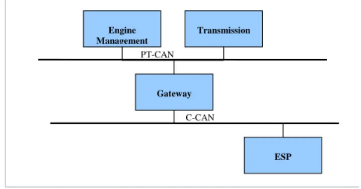
The hardware architecture is modeled in parallel to the definition of the software architecture. AUTOSAR allows for modeling the topology of a vehicle network as well as the hardware of an ECU. An example of this topology can be seen in Figure 2.
Engine Management Transmission Gateway ESP PT-CAN C-CAN
Figure 2: Exemplary network topology
The example shows two ECUs connected to a powertrain CAN network (PT-CAN) and one ECU
connected to a chassis CAN network (C-CAN). The two CAN busses are connected through a gateway. Once the software architecture and the network topology are defined, the software entities can be mapped to the hardware entities. The Software
Component Template standardizes the format for
describing the software entities and is a very important part of the AUTOSAR metamodel. It defines how the software architecture is specified.
3. Application Interfaces
Besides the metamodel, which defines how an application interface is described, AUTOSAR specifies application interfaces as well. Standardized application components are organized in a hierarchical way [8]. The top hierarchical level consists of the following functional domains:
• Powertrain; • Chassis; • Body; • Safety;
• Multimedia, Telematics and HMI.
Structures are elaborated for the first three domains in phase 1 of AUTOSAR which ended in 2006
The Body domain usually includes access subsystem, visibility subsystem, comfort subsystem, acoustic warnings etc. The Powertrain domain coordinates torque producing, distributing and consuming components (e.g. engine, transmission) in close interaction with the chassis domain, which in its turn is responsible for suspension, brakes, driving dynamics and so on.
Multimedia, telematics and HMI and safety domains were not elaborated in phase 1.
The top level decomposition into 5 domains is based on a traditional structure of vehicle domain decomposition rather than on flexible functional vehicle model and thus couldn’t be considered as the best way to represent software architecture. Compositions done by the traditional structuring are tending to represent rather currently available products (such as ESP, ACC etc.) than generalized view of software architecture. Such an approach does not contribute to future development prospective. Orientation on currently available products can be considered as advantage in short term since it allows for easy adaptation of existing software to be used in AUTOSAR-based systems. On the other hand, in long-term prospective such approach can aggravate the implementation of new functionalities and induce ambiguousness in their referring to standardized components thus causing interoperability and portability problems.
In further sections of this paper some functional structuring approaches will be considered. The application of their principles towards the AUTOSAR application software architecture serves as a
measure to elaborate the possibility to link the AUTOSAR application SW-Cs to a functional model.
4. Overview of existing approaches
In the literature one can find several concepts to structure the functionality of a vehicle into a consistent model. In this section we present two of them.
4.1. Module Concept
The European funded project SPARC (Secure Propulsion Using Advanced Redundant Control) [10] dedicated to development of a safety decision control system for an accident-avoiding vehicle introduced a module-oriented concept. They distinguish the following architectural layers [11]: • Command layer - responsible for working out a
desired motion vector derived from the driver inputs, supported by the human-machine interface (HMI) and the advanced driver assistance systems (ADAS);
• Co-ordination layer - creates a secure motion vector for any driving situation by combining and arbitrating the inputs from the driver and the ADAS;
• Execution layer - consists of the steering system, braking system, power pack and energy system and maps the motion vector to physical reality by means of actuator control.
Passenger Management functionalities are out of scope of SPARC.
The basic principle emphasized in SPARC architecture is separation of decision making (command or strategic) layer and layer to realize made decision (execution layer) which are glued together via co-ordination layer. One of the goals of the SPARC is to demonstrate the scalability (ability to be used on the vehicle of different size) and transferability (ability to be used on the vehicle of different kind) of developed safety-related functionalities ensured by the separation of three layers.
Such kind of layered structure provides the high level of abstraction for the interface between the part responsible for working out of ultimate decision on vehicle behavior in current situation and the part which performs the execution of the decision by means of control of actuators to the high abstraction level. This allows making command layer software entities independent of actual set and characteristics of actuators and other means of control installed in a particular vehicle and in that way facilitates their reusability.
This approach can be extended to encompass all vehicle systems [9]. In case of such extension the
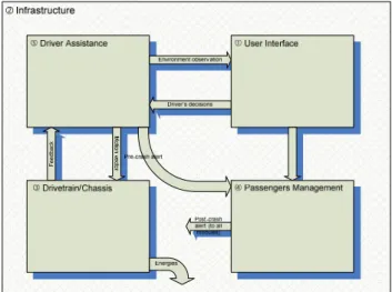
vehicle architecture can be divided in 5 functional modules: 1. User Interface 2. Infrastructure 3. Drivetrain/Chassis 4. Passenger Management 5. Driver Assistance
User Interface module is responsible for all information interactions with driver and passengers: capturing input data (including driving-related intensions), transferring it to other modules, getting feedback information and presenting it to users. Driver Assistance module performs evaluation of environment conditions basing on sensor data, generates current motion strategy and combines it with driver intensions arriving from user interface module by means of arbitration logic. The output is a motion vector to be implemented by Drivetrain/Chassis module. This module encapsulates the means of execution of required motion vector, stability functions based on reactive environment evaluation and energy creation and management. Passenger Management carries out all non-driver-specific tasks including infotainment, climate control, passive safety, windows, roof, door lock control etc. All mentioned modules are interconnected through an infrastructure module which provides energy, power and signal distribution, means of communications with multiplexing and gateways, means of wireless connectivity.
General modularization of the 5 module concept is shown in the Figure 3.
Figure 3: Module Decomposition
Basic criteria for the module decomposition look simple and clear enough, but there could be sensors which are used together by driver assistance module and drivetrain/chassis module, this fact results in need of widening of interface between these modules and blurs the boundary between them in
terms of assignment of components to a specific module.
Whereas this structuring principle is based on the effective implementation of the motion vector, different structuring principles exist in literature. A further one will be presented in the next chapter. 4.2. CARTRONIC
CARTRONIC is proposed by Robert Bosch GmbH as an “open architecture for networking the control systems of an automobile” [7]. It introduces systems,
components and communications as the elements of
the architecture. System is considered as a set of components and communications that are integrated by function. Communications include orders, responses, requests and inquiries. Order is a direct instruction to the receiving component to perform particular action. Response with the reason is sent by receiving component if the order cannot be fulfilled. Component can also inquire for necessary information and request another component to do something.
Possible communications between systems and components are restricted with the following structuring rules [7]:
1. A component can only get an order from one single source component (hierarchical flow of orders);
2. Inquiries and requests are possible on the same layer and upwards into higher layers.
The first rule supports the avoidance of conflicts between different orders and clear allocation of responsibilities in the structure. It also implies the presence of a coordinator component in each subsystem which dispatches orders to the
embedded components. The second rule contributes to the component interchange and reuse.
CARTRONIC distinguishes 3 types of components according to their functional roles:
• coordinators – perform resource management, conflict detection and resolution etc.;
• components with mainly operational tasks – execute orders, report resource requirement, provide resources etc.;
• information providers.
CARTRONIC functional architecture is based on the following principles:
• each system is made up of self-contained components with a minimal number of physical interfaces;
• each system/component fulfills clearly defined tasks autonomously by obtaining information and initiating orders;
• superordinated decision makers are used to coordinate systems/components, they derive one single decision from the competing results; • orders are propagated hierarchically from initiator
• the interfaces of each system/component are known to as many other systems/components as necessary and as few as possible.
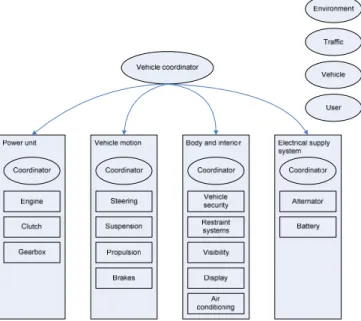
On the high abstraction layer the structure of the entire vehicle consists of one vehicle coordinator, four components with operational tasks (control of power unit, control of vehicle motion, control of body and interior and control of electrical supply system) and four information providers (environment, traffic, vehicle and user), see Figure 4.
Figure 4: CARTRONIC Vehicle Architecture Although CARTRONIC principles constitute an effective way to manage vehicle electronic systems complexity their software implementation in the straightforward way can encounter the following difficulties:
• high complexity of coordinators (mostly in power unit, vehicle motion and vehicle coordinator due to strong dependencies between power unit and vehicle motion),
• high communication overhead between coordinators and coordinators and other components.
Such concentration of complexity and communications in coordinator components can jeopardize the fulfillment of timing and memory consumption constraints.
5. Combined framework for AUTOSAR software architecture
The major difference of architectural approaches described above consists in the fact that Module Concept has an underlying use case as a background when CARTRONIC is based on traditional vehicle structure partitioning. The use case implied by 5 Modules comprises independent operation of driver assistance system, arbitration of their decisions against captured driver’s intensions
and implementation of arbitration outcome by vehicle drivetrain. A framework to be applied to the AUTOSAR-based software architecture can be composed as a combination of mentioned approaches.
The top level structure of the framework can be inherited from 5 Modules, first of all, the idea of separation of strategic layer responsible for making decisions on vehicle motion vector and execution layer responsible for the implementation of the motion vector is to be adopted.
Hierarchical rules of CARTRONIC can be used in definition of internal structures of the modules. Due to integration of all components controlling chassis and powertrain into a single Drivetrain module the overhead caused by complexity and communication concentration in coordination components will be mitigated. Generalized view of the architecture framework combined from 5 module concept with CARTRONIC principles is shown in Figure 5 (infrastructure module is not shown).
Figure 5: Combined framework
The driver assistance module should encompass components whose task consist in making decision on the motion direction counting on safety and comfort concerns, current motion parameters, driver decisions and environmental information. Drivetrain/chassis module consists of the components directly controlling the chassis and powertrain systems basing on driver assistance module requests, providing necessary level of stability in requested motion vector, sensing the parameters of engine(s), brakes, suspension etc. User interface module includes all components responsible for getting driver and passenger intensions and information (from steering wheel, pedals, switches, knobs other controls) and presenting information to users (telltales, displays, feedback devices). Passenger management module contains components which are not concerned to the vehicle motion and interactions with users.
Alignment of AUTOSAR software architecture with generic framework like described above will provide some means to establish the links with arbitrary (i.e. OEM-specific) vehicle-level functional model.
6. Application of framework to the AUTOSAR-based software architecture
6.1. General Considerations
To make use of a framework in connection with AUTOSAR-standardized components the links between these two representations are to be established. In general case the task consists in the mapping of one hierarchical set of interconnected entities (AUTOSAR standardized SW-Cs) to another one (framework). Due to differences in structuring principles of these models most likely the direct one-to-one links could not be preserved for all SW-Cs: for some of them additional considerations of their internal structure and decomposition in order to distribute a component between several modules of target framework will be required. The goals of mapping are to find the way how the SW-Cs are linked to the entities of a framework, to determine which parts of functionalities are covered by particular SW-Cs and where are the boundaries of different functional domains of the framework within SW-Cs.
It is important to have criteria for decomposition which is based on the characteristics of the framework structure. For the first iteration in order to find initial assignment of AUTOSAR components to target modules (one-to-one or one-to-many) and to ascertain the necessity of decomposition of particular components the criterion of functionality can be used. It consists in comparison of the sets of functionalities associated with functional modules and software components. Presence of equivalent functionalities will indicate the necessity to establish a link between entities under consideration. The functional criterion is not quite strict to cope with all ambiguities and controversial issues of the mapping, this makes it a simple guideline to be used on initial stages. It does not provide enough means to find exact ways of software entities decomposition and does not allow for setting of the boundaries of framework modules within them.
Another criterion which potentially can give more precise results is the criterion of interfaces between the framework entities. To apply this criterion, the framework structure should be considered in regard of interfaces between the entities. The prerequisite for interface-based decomposition is the strict and unambiguous definition of those interfaces within a framework. The internal structure of software entities is to be analyzed in order to reveal particular layers where the interface is equivalent or consistent to the interface between framework entities. Disclosed interface layer will represent the required boundary.
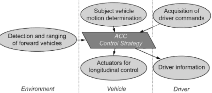
6.2. Application example: Adaptive Cruise Control The functionality of ACC is described in [6] as carrying out a part of longitudinal control strategy basing on information about forward vehicles, own vehicle and drivers command. Basic intention of the ACC longitudinal control strategy is the automatic control of vehicle speed (in some range) to maintain either a time gap to a forward vehicle or to maintain the set speed, whichever speed is lower. Further the ACC with speed control, time gap control and active brake control capabilities will be considered as the most general case. The functional structure of ACC according to [6] is shown in Figure 6.
Figure 6: Structure of the ACC according to ISO 15622
The following functionalities are associated with the ACC component:
• Determining of ACC-specific vehicle state
• Sensor data processing and surrounding vehicle detection
• Selection of target vehicle for time gap control • Time gap control acceleration request calculation • Speed control acceleration request calculation • Active strategy selection
• Comfort acceleration arbitration (including forming comfort-related requests to brake and transmission systems)
The list shows that overall ACC functionality crosses the boundary of top level domains in the AUTOSAR representation: input data for ACC are provided by sensors from Chassis and Powertrain domains, as well as the actuators for longitudinal control implementation are belonging to the same two domains. Thus, in AUTOSAR specification more than one SW-C will be involved in the overall ACC operation.
Consideration of the ACC functionalities and definition of reference model shows, that most likely they are to be split between Driver Assistance and Drivetrain modules. Interface analysis is required to find the boundary within the component.
As follows from the description of the 5 modules, the interface between Driver assistance module and Drivetrain module is described as “motion vector”. For such interface the most appropriate level of interface abstraction is the level of physical motion
parameters as speeds (longitudinal and lateral), accelerations, yaw rates etc. The SW-Cs intended to form ACC acceleration request and to arbitrate it with acceleration requests from other comfort- and safety-related ADAS are to be referred to the strategic Driver Assistance module and SW-Cs concerned to the implementation of supplied acceleration request - to the Drivetrain module. More thorough consideration by domain experts is required to determine exact boundary in accordance with formulated guidelines.
6.3. Principles shown in a demonstrator
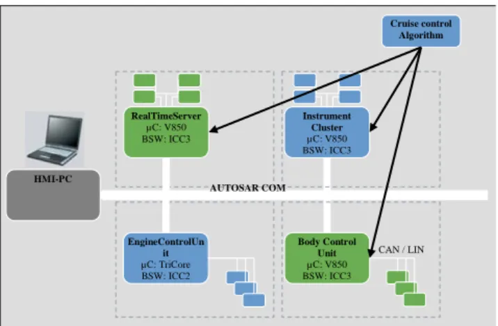
The principles considered in the previous sections were realized in a demonstrator. The main functionality is cruise control. This is especially of use to show the principles of AUTOSAR and the functional model concepts as it is a function that needs data from several sensors out of different domains, has a central – domain independent – responsibility to process the data and uses several output devices. With that, this function has many aspects that are suitable to show several of the main objectives of AUTOSAR. But to show the interaction with other functionality, additional applications are realized as ASW components. These are air conditioning, wiper washer, window lifter, and central door locking.
The demonstrator consists of a set of four ECUs with reduced functionality and an additional PC. They are connected via a high speed CAN. Three of them are based on NEC V850 hardware and one on TriCore µC. The PC is used for the central control of the whole functionality, restbus simulation and HMI purposes. On the V850 ECUs an ICC31 AUTOSAR BSW stack is implemented. On the TriCore µC an ICC2 implementation of the AUTOSAR BSW stack is realized. Each ECU takes over a specific role in the network. One takes over the responsibility of a real-time server, one of an engine control unit, one of a body control unit and one of an instrument cluster control unit. Sensors and actuators are connected via CAN to one of the ECUs.
1
AUTOSAR defines three implementation
conformance classes (ICC). ICC1 is the black box view on the BSW. ICC3 is the module level view on the BSW. In ICC2 several modules are combined into different clusters.
HMI-PC CAN / LIN AUTOSAR COM Cruise control Algorithm Body Control Unit µC: V850 BSW: ICC3 EngineControlUn it µC: TriCore BSW: ICC2 RealTimeServer µC: V850 BSW: ICC3 Instrument Cluster µC: V850 BSW: ICC3
Figure 7: Cruise control demonstrator
The whole system is placed in two transportable suitcases, such that it can be used for demonstrations to the customer. Each of the involved subdomains can now illustrate how the specific ECU works in the cross domain network of AUTOSAR ECUs.
7. Conclusion
Attempts to arrange the architecture of AUTOSAR-based vehicle system using the arbitrary functional model along with its structuring principles require finding of appropriate mapping between AUTOSAR architecture and target model, i.e. determination of correspondence between their entities.
In general case mapping of SW-Cs to the entities of different functional models will require consideration of their internal structure since necessity of further decomposition is anticipated.
To find the optimal way of mapping, two criteria can be used: functional equivalence and interface consistency. Well defined interaction patterns, clear and strict structuring principles of target functional model become key factors in successful mapping. In this paper a couple of approaches from the automotive world were described to form a sort of reference functional framework. Its application was demonstrated on an example of Adaptive Cruise Control.
Usually the OEM is the developer and owner of the functional model of a vehicle and the supplier develops the software on subsystem level. To improve the reuse of this software, the supplier has an interest to map the software components to as many functional models from different OEMs as possible. The framework presented in this paper enables the mapping of functional models on vehicle level with hierarchies of AUTOSAR software compositions. It will be used to embed the implementations of software components to the functional models in future series projects.
[1] AUTOSAR Main Requirements, Version 2.0.1, AUTOSAR Consortium, 2006
[2] AUTOSAR Technical Overview, Version 2.0.1, AUTOSAR Consortium, 2005
[3] AUTOSAR Glossary, Version 2.0.1, AUTOSAR Consortium, 2005
[4] AUTOSAR Software Component Template, Version 2.0.1, AUTOSAR Consortium, 2006 [5] Meta Object Facility (MOF) Core Specification,
Version 2.0, Object Management Group, 2006 [6] ISO 15622: Transport information and control
systems Adaptive Cruise Control systems -Performance requirements and test
procedures
[7] CARTRONIC – An Open Architecture for Networking the Control Systems of an Automobile, Torsten Bertram, Rainer Bitzer, Rainer Mayer, Asmus Volkart, Robert Bosch GmbH
[8] A. Gilberg: The long terms impacts of
AUTOSAR on development costs and quality management of tomorrow's vehicles;
International Automotive Electronics Congress, Paris, 2007.
[9] Frédéric Holzmann, Adaptive Cooperation between Driver and Assistant System: Improving Road Safety, Springer Verlag, Berlin, 2007
[10] Secure Propulsion Using Advanced Redundant Control (SPARC); eSafety of road and air transport initiative; 2006.
[11] SPARC Deliverable D3: Specification document on SPARC interfaces and
architecture, Version 1.0, Michael Armbruster, Matthias Feiler, Frederic Holzmann, Joahim Irion, Ansgar Maisch, Armin Sulzmann, Manfred Thanner, The SPARC Consortium
9. Glossary
ACC: Adaptive Cruise Control
ADAS: Advanced Driver Assistance Systems ASW: Application Software
AUTOSAR: Automotive Open System Architecture BSW: AUTOSAR Basic Software
ECU: Electronic Control Unit HMI: Human-Machine Interface RTE: AUTOSAR Runtime Environment SW: Software
SW-C: AUTOSAR Software Component VFB: AUTOSAR Virtual Functional Bus VLC: Vehicle Longitudinal Control