Development of Resource-Constrained Sensors and
Actuators for In-Space Satellite Docking and
Servicing
by
Duncan Lee Miller
s85 n
Submitted to the Department of Aeronautics and Astronautics
t
in partial fulfillment of the requirements for the degree of
Ct
cc
OLL
:z
m
Master of Science in Aeronautics and Astronautics
at the
MASSACHUSETTS INSTITUTE OF TECHNOLOGY
June 2015
@
Massachusetts Institute of Technology 2015. All rights reserved.
,Signature redacted
A uthor ...
Department of Anautics and Astronautics
Signature redacted
Certified
by...
...
David W. Miller
Professor of Aeronautics and Astronautics
Signature redacted
Certified
by...
Alvar Saenz-Otero
Principal Research Scientist
,Signature
redacted
Accepted by ...
..
Paulo C. Lozano
Associate Professor of Aeronautics and Astronautics
Chair, Graduate Program Committee
Development of Resource- Constrained Sensors and
Actuators for In-Space Satellite Docking and Servicing
by
Duncan Lee Miller
Submitted to the Department of Aeronautics and Astronautics on May 21, 2015, in partial fulfillment of the
requirements for the degree of
Master of Science in Aeronautics and Astronautics
Abstract
Most satellites on-orbit today are not intended to physically approach or interact with other spacecraft. However, the robotic servicing of orbiting assets will be an economically desirable (and often scientifically necessary) capability in future space enterprises. With the right set of tools and technologies, satellites will be able to autonomously refuel, repair, or replace each other. This has the potential to extend mission lifetimes, reduce orbital debris and make space more sustainable. Spacecraft may also assemble on-orbit into larger aggregate spaceflight systems, with applications to sparse aperture telescopes, solar power stations, fuel depots and space habitats. The purpose of this thesis is to address the highest risk elements associated with the docking and servicing of satellites: the sensors, actuators, and associated algorithms. First, a peripheral agnostic robotics platform is introduced, upon which a suite of technology payloads may be developed. Next, a flight qualified docking port for small satellites is presented, and the results detailing its operation in a relevant environ-ment are discussed. In addition, we review a high precision relative sensor designed to enable boresight visual docking. The measurements from this optical camera are applied to a nonlinear estimator to provide the highly accurate sensing necessary for docking. Finally, a free-flying robotic arm is examined and modeled as an experimen-tal payload for the SPHERES Facility on the International Space Station.
Thesis Supervisor: David W. Miller
Title: Professor of Aeronautics and Astronautics Thesis Supervisor: Alvar Saenz-Otero
Acknowledgments
The work in this thesis related to the SPHERES Docking Ports and the SPHERES Halo was supported by NASA and DARPA under the InSPIRE-II contract, #NNH13CJ23C. In addition, the entirety of this research was conducted with Government support
un-der and awarded by the Department of Defense (DoD), Air Force Office of Scientific Research, National Defense Science and Engineering Graduate (NDSEG) Fellowship, 32 CFR 168a. The author gratefully thanks these sponsors for their generous support that enabled this research.
I would also like to thank my advisors Professor David W. Miller arid Dr. Al-var Saenz-Otero for giving me the opportunity to participate and contribute to the SPHERES project. I am honored to have worked side-by-side with a first-class team of graduate and undergraduate students throughout my tenure at MIT. I would like to thank both current and past team members for estabilishing and maintaining such a strong program. The collection of professional engineers at Aurora Flight Sciences also deserve a large amount of credit for their commitment and contributions to the MIT Space Systems Lab. Thank you all for your tireless pursuit of a better future in space.
Contents
1 Introduction
1.1 Motivation for In-Space Satellite Cooperation . . . . 1.2 Existing and Planned Testbeds and Technical Demonstrations . 1.2.1 SPH ER ES . . . . 1.2.2 DARPA Phoenix . . . .
1.2.3 RSGS . . . . 1.3 Thesis Approach . . . .
2 Framework: Peripheral Agnostic lite Servicing Toolbelt
2.1 Overview . . . . 2.2 Hardware Platform . . . . 2.3 Software Architecture . . . . 2.4 Halo Guest Scientist Program
2.4.1 Test Project Methods . 2.4.2 PeripheralCore Methods 2.5 Comparison to Existing Robotic
. . . . 22
. . . . 23
. . . . 24
Software Architecture for a Satel-27 . . . . 27 . . . . 28 . . . . 30 . . . . 34 . . . . 34 . . . . 35 Frameworks . 36 3 Actuator: Flight Hardware Design of a Rigid Androgynous Docking Port 3.1 O verview . . . . 3.2 SDacecraft Docking Port Design Space . . . . 39 39 40 3.2.1 Docking Port Classifications . . . . 41 15
15 19 20
3.2.2 Docking Port Attributes . . . . 44
3.3 Ground Prototype Design . . . . 46
3.4 Flight Requirements Flowdown . . . . 48
3.4.1 Design Drivers . . . . 48
3.4.2 Requirements Matrix . . . . 49
3.5 Flight Design Review . . . . 51
3.5.1 Mechanical Overview . . . . 54
3.5.2 Electrical and Operational Overview . . . . 56
3.5.3 Specifications Overview . . . . 57
3.6 Validation in Three Degrees-of-Freedom . . . . 57
3.6.1 Ground Test Objectives . . . . 58
3.6.2 Concept of Operations . . . . 59
3.6.3 Experimental Results . . . . 60
3.7 Validation in Six Degrees-of-Freedom . . . . 62
3.7.1 RGA Objectives . . . . 63
3.7.2 RGA Results . . . . 63
3.8 Lessons Learned.. .. . . . . .. . . . . 74
3.9 Planned ISS Operations . . . . 75
4 Sensor: Relative Pose Estimation of a Spin-Stabilized 4.1 O verview . . . . 4.1.1 Requirements . . . . 4.1.2 Instantiation . . . . 4.2 Measurements . . . . 4.2.1 Fiducial Markers . . . . 4.2.2 Marker Detection and Image Filtering . . . . . 4.2.3 Perspective Four Point Correspondence . . . . . 4.2.4 Camera Calibration . . . . 4.2.5 Camera Accuracy . . . . 4.2.6 Measurement Modeling . . . . Spacecraft 79 . . . . 79 81 . . . . 83 . . . . 84 . . . . 85 . . . . 86 . . . . 88 . . . . 90 . . . . 93 . . . . 96
4.3.1 Process Noise Modeling . . . . 102
4.4 Multiplicative Extended Kalman Filter . . . . 103
4.4.1 Re-parameterize . . . . 103
4.4.2 Linearize . . . . 104
4.4.3 Propagate . . . . 106
4.4.4 Measurement Update . . . . 107
4.5 Unscented Kalman Filter . . . . 108
4.6 Validation in Simulation . . . . 110
4.6.1 Representative Convergence . . . . 111
4.6.2 Representative Errors . . . . 115
4.6.3 Modeling Variations . . . . 117
4.6.4 Montecarlo Simulation . . . . 119
4.7 Validation in Three Degrees of Freedom . . . . 121
4.7.1 Ground Test Objectives . . . . 121
4.7.2 Experimental Results . . . . 121
4.8 Validation in Six Degrees of Freedom . . . . 124
4.8.1 RGA Objectives . . . . 124
4.8.2 RGA Results . . . . 124
4.9 Summary and Conclusions . . . . 126
5 Actuator: Prototype Design of a Free-Flying Robotic Manipulator 129 5.1 O verview . . . . 129
5.2 Literary Research . . . . 130
5.3 Hardware Design . . . . 138
5.3.1 Lego Arm Overview . . . . 139
5.3.2 SPHERES Ambulant Robotic Manipulator (ARM) . . . . 140
5.4 Arm Control and Simulation . . . . 148
5.4.1 Inverse Kinematics . . . . 149
5.4.2 Dynamic Modeling . . . . 154
5.5 Verification in Three Degrees-of-Freedom. . . . 5.6 Future Work . . . .
6 Conclusion
A Additional Mathematical Definitions
A.1 Additional Mathematical Definitions . . . . A. 1.1 Quaternion . . . . A.1.2 Inertia Definition . . . . A.1.3 Full Linearization of the Euler Dynamics . . . .
B Source Code
B.1 Multiplicative Extended Kalinan Filter . . . . . B.2 Unscented Kalman Filter . . . .
157 159 161 173 173 173 174 174 177 177 184
. . . .
. . . .
List of Figures
1-1 The Enormous Scientific Return from Hubble Would Not Have Been Possible Without Post-Launch Servicing Missions [1] . . . . 16 1-2 There Is A Large Economic Incentive To Mass Producing Aerospace
System s [2] . . . . 17 1-3 SPHERES Aboard the ISS [31 . . . . 21 1-4 The Principle Systems Involved in the DARPA Phoenix Project [4] . 22 1-5 An Overview of the Robotic Servicing of Geostationary Satellites (RSGS)
DARPA M ission . . . . 24 1-6 Phases of Servicing . . . . 25
2-1 Halo Prototype Hardware that Supports Peripherals On Up To Six H alo P orts . . . . 28 2-2 Currently Compatible Halo Peripherals Include Docking Ports, Stereo
Vision Cameras, Control Moment Gyro's, Thermno-Imagers, Lidars, and Robotic Manipulators . . . . 29 2-3 An Object Oriented Approach to Flight Software Supports Multiple
Peripherals Simultaneously . . . . 31 2-4 Current Peripheral Cores Supported By The Halo Software Framework. 32 2-5 Halo Software Flow Diagram (adapted from [5]) . . . . 33 2-6 Representative Thread Execution During a HaloCore Test Project . . 34
2-7 An Overview of Where the Halo GSP Platform Fits in the Larger Landscape of Robotics Platforms . . . . 38
3-2 The SPHERES Prototype Universal Docking Port Mechanism and Ac-companying Avionics Board . . . . 46 3-3 The SPHERES SWARM Docking Assembly on the MIT Flat Floor . 47 3-4 The SPHERES-VERTIGO-UDP Flight Assembly. . . . . 52 3-5 The Secondary In-Space Flight Configurations Through the
Mechani-cal Standoff (left) and the Halo (right). . . . . 52 3-6 The Fleet of SPHERES Universal Docking Ports Ready for Shipment. 54 3-7 Exploded view of the internal UDP mechanism. . . . . 55 3-8 [Animation] Front View of An Animated Locking Sequence (Press Play
to Start V ideo) . . . . 56 3-9 [Animation] Side View of An Animated Locking Sequence (Press Play
to Start V ideo) . . . . 56 3-10 Functional Block Diagram of the UDP Electrical System . . . . 57 3-11 Glass Table Facility at MIT Used for Ground Testing of the UDP . . 58 3-12 Glass Table Concept of Operations . . . . 59 3-13 Velocity-Controlled Results from Three Degree of Freedom Testing on
the MIT Glass Table (Adapted from [6]) . . . . 61 3-14 [Animation] A Successful Docking Test Achieved by the SPHERES
on the Glass Table Using the Proto-Flight Docking Ports (2X Speed; Synchronized Camera Sensing Shown in Upper Right) . . . . 62 3-15 Sample Accelerometer Response Throughout an Entire Parabola
(Zero-gravity Begins at 31s). . . . . 66 3-16 Sample Gyro Response Throughout an Entire Parabola (zero-gravity
begins at 31s). . . . . 67 3-17 Raw Accelerometer and Gyro Data with Moving Average Filter . . . 67 3-18 Final Unbiased Acceleration and Angular Velocity Response to a Single
T hruster Pulse. . . . . 68 3-19 Configurations for the System Identification Analysis on Flight 1 (top
left and right), Flight 3 (bottom left), and Flight 4 (bottom right). . . 69
3-21 SPHERES Docking Port Test Session Plans Build Toward Halo
Oper-ation s . . . . 78
4-1 Concentric Circle Fiducial Markers Have Previously Been Used on the Exterior of the ISS . . . . 80
4-2 The SPHERES Universal Docking Port (left) and Necessary Docking Tolerances (right) . . . . 81
4-3 The Linear and Angular Error Constraints Needed to Achieve Docking. Green Is Within the Hole. Orange Is Within the Capture Cone. Red Is Outside The Capture Cone. . . . . 82
4-4 The Selected COTS Camera for Integration into the SPHERES UDP. 84 4-5 The Selected Fiducial Markers for the SPHERES UDP. . . . . 85
4-6 The Area Ratios of the Fiducial Markers are Spaced Linearly. . . . . 86
4-7 The Result of Performing Adaptive Thresholding on a Grayscale Image and Its Inverse ... ... 87
4-8 Four Point Correspondence Geometry of Haralick's Iterative Nonlinear Solution to Exterior Orientation [7]. . . . . 89
4-9 The Camera Calibration Process Used for the UDP Camera . . . . . 91
4-10 Uncorrected Mean Reprojection Error Anomalies Due to Rolling Shutter 92 4-11 Corrected Mean Reprojection Error Anomalies of a Rolling Shutter C am era . . . . 93
4-12 Optical Setup for Measuring Sensing Error . . . . 94
4-13 Absolute Error in the X-Direction from 13.9 cm Range . . . . 94
4-14 Absolute Error in the Y-Direction from 13.9 cm Range . . . . 95
4-15 Absolute Depth Error in the Z-Direction from 13.9 cm Range . . . . 95
4-16 This graphic shows higher measurement sensitivity (lower noise) for an x-axis twist (blue is the image plane). . . . . 97
4-17 This graphic shows lower measurement sensitivity (higher noise) for a y- or z-axis tilt (blue is the image plane). . . . . 98
4-18 Examples of a False Negative Measurement (left) and a False Positive M easurem ent (right). . . . . 99 4-19 [Animation] The Proposed Concept of Operations for Relative Pose
E stim ation. . . . . 100 4-20 Representative tracking of position states with full noise modeling. . 112
4-21 Representative tracking of velocity states with full noise modeling. . 113 4-22 Representative tracking of quaternion states with full noise modeling. 114 4-23 Representative tracking of angular velocity states with full noise
mod-elin g . . . . 1 15 4-24 Representative quaternion error with full noise modeling. . . . . 116 4-25 Representative angular velocity error with full noise modeling. . . . . 117 4-26 Representative angular velocity error with full noise modeling. . . . . 118 4-27 Representative angular velocity error with full noise modeling. . . . . 119 4-28 The non-dimensional performance of the MEKF and UKF filters (lower
is b etter) . . . . 120 4-29 [Animation] Real-Time iducial Tracking (Target Is Locked) . . . . 122 4-30 Quaternion estimate of the state in the SPHERES hardware demo . . 122 4-31 Angular rate estimate of the state in the SPHERES hardware demo . 123 4-32 [Animation] Real-Time Fiducial Tracking During Undocking (Target
Is Locked) ... ... 125
5-1 Two views of the Space Station Remote Manipulator System (ie Canadarm 2 ) [8] . . . . 13 1 5-2 The Canadian Built Dextre has been Operational Aboard the ISS Since
2008 [9] . . . . 132 5-3 The Japanese Experiment Module (JEM) Remiote Manipulator System
(R M S) [10] . . . . 132 5-4 The Robonuat Arms Are Capable of Grasping Tools [11] . . . . 133 5-5 The Engineering Test Satellite VII Robotic Arm [12] . . . . 134 5-6 The Orbital Express OEDMS Robotic Arm During Final Assembly [13] 134
5-7 The European Robotic Arn (ERA) [14] . . . . 135
5-8 The Ranger Dexterous Manipulator [15] . . . . 136
5-9 The Dynamic Manipulation Flight Experiment (DYMAFLEX) [16] . 137 5-10 The Front-end Robotic Enabling Near-term Demonstration (FREND) [17] ... . . . . .138 5-11 An Assembly Overview of the SPHERES Lego Robotic Arm . . . . . 139
5-12 Evolution of the SPHERES-ARM Over Three Generations of Designs 142 5-13 A Mechanical and Electrical Prototypes of the Second Generation SPHERES-ARM . . . . 143
5-14 The Design of the Third Generation SPHERES-ARM Prior to Manu-facturing . . . . 145
5-15 The Fin Ray Gripper Can Apply Equal Pressure Gently But Firmly to an E gg [18] . . . . 146
5-16 The Proposed Fin Ray Gripper Design for the SPHERES ARM . . . 147
5-17 Two SPHERES-ARMs Mounted on the Halo for Satellite Servicing A ctivities . . . . 148
5-18 Conjoined Circle Method (CCM) for Inverse Kinematics . . . . 150
5-19 Conjoined Circle Method for 3 DoF . . . . 150
5-20 Conjoined Circle Method for 3 DoF . . . . 152
5-21 [Animation] A Visualization of the Inverse Kinematics Solver for A Fixed-Base, 3D Robotic Arm . . . . 154
5-22 The Proposed Angle Displacement Method for A Two-Segment Body 155 5-23 [Animation] Dynamic Simulation of a Free-Floating Satellite and Pla-nar M anipulator . . . . 156
5-24 [Animation] Dynamic Motion Study of a Robotic Arm and a SPHERES H alo . . . . 157
5-25 [Animation] Hardware Demonstration of the Lego Robotic Arm Exe-cuting the Same Open Loop Controls as Figure 5-23. . . . . 158
5-26 Results from the Lego Arm Hardware Demonstration Including Actu-ator Commands and Rotational Feedback . . . . 159
List of Tables
2.1 Virtual Methods Implemented in a Test Project . . . . 35
2.2 Necessary Virtual Methods for a Guest Scientist Payload . . . . 35
3.1 Docking Port Classification Matrix . . . . 41
3.2 Consolidated Requirements Matrix . . . . 50
3.3 Specification Summary of the Flight UDP Compared with the Ground P rototype . . . . 58
3.4 Summary of Test Configurations and Accomplishments . . . . 64
3.5 Experimental and CAD Predictions of the Assembly Centers of Mass 73 3.6 Experimental and CAD Predictions of the Assembly Inertia Matrices 73 4.1 Consolidated Requirements Matrix for the UDP Sensor . . . . 82
Nomenclature
AFS Aurora Flight Sciences
CoM Center of Mass
COTS Commercial Off The Shelf
DARPA Defense Advanced Research Projects Agency DOF Degree of Freedom
ESA European Space Agency GSP Guest Scientist Program ISS International Space Station
MIT Massachusetts Institute of Technology
NASA National Aeronautics and Space Administration OOP Object Oriented Programming
OS Operating System
PADS Position and Attitude Determination System RGA Reduced Gravity Aircraft
RMS Root Mean Square
RSGS Robotic Servicing of Geostationary Satellites
SPHERES Synchronized Position Hold Engage and Reorient Experimental Satellites SSL Space Systems Laboratory
USB Universal Serial Bus
Chapter 1
Introduction
1.1
Motivation for In-Space Satellite Cooperation
Spacecraft rendezvous and docking is becoming increasingly frequent with the growing com-mercialization of space. By far the most common application of docking is in the delivery of crew members or supplies to an orbiting space station. However, the applications of satellite cooperation extend far beyond the transportation of assets into Low Earth Orbit (LEO). In this section, we show that for both economic and scientific purposes, satellite cooperation makes sense for many applications.
The notion of satellite cooperation suggests varying degrees of synergism between space-craft on-orbit. The technology developed in this thesis (specifically, the requisite sensors and actuators) relates to both the servicing of known and unknown systems, and the assembly of aggregative spacecraft structures .
Satellite servicing on orbit is an emerging technology enabler that can affect a broad class of missions. Once mature, in-space servicers can provide satellite operators the necessary resources to diagnose anomalies on orbit, correct mechanical and electrical problems, and repeatedly enhance our high-value assets over long periods of time. This paradigm of inspecting, repairing and upgrading vehicles exists everywhere on Earth, but not in space [2]. Consider aircraft, ships and automotives; all are re-furbished and often improved over their lifetime. There is no question that this capability boosts the return on investment in these machines.
obser-vatories ever built. Hubble launched in 1990 but required multiple servicing missions in order to reach its full potential as an effective star-gazer. Figure 1-1 shows graphically the enormous effects that servicing had on the HST mission. The Davidson metric is a measure of NASA contributions to worldwide scientific discovery and technological achievement.
70
-Hubble
HST
-Chandra 60 s- sT -GRO -Voyager -Viking ---vika 50 - --- MGSSM2
I-Cas/niSon7
M40- -Ad" 40 ST*S Rocets/alloorts .3 -- P 0M1 4); C 0 IA I, 0 30 - -- -20Launch
IV.Figure 1-1: The Enormous Scientific Return from Hubble Would Not Have Been Possible Without Post-Launch Servicing Missions [1]
Each HST servicing mission involved high precision rendezvous, delicate component inspection and replacement, and upgraded instrument installation. Once the telescope was redeployed, the shuttle usually re-boosted Hubble's orbit to correct for atmospheric drag and further extend the life of the satellite. From conception, Hubble was designed to be serviced by spacewalking shuttle astronauts, but this is rare. Despite its success, the Hubble servicing scenarios were performed at high cost and risk to human life. Robotic servicers are an alternative methodology promising to provide many of the same (or better) capabilities at lower cost and complexity to human space flight.
Satellite cooperation extends to on-orbit assembly of spacecraft as well. In the same way that organic cells work together to form a larger organism, smaller satellite modules (or satlets) may aggregate together in-space to achieve greater scientific and economic re-turns. The cellularized approach to satellite construction is a potentially disruptive space
technology promising at least an order of magnitude reduction in cost for equal or greater performance [19]. Such fractionated spacecraft support dynamic reconfigurability on-orbit and allow for spacecraft electronics refreshes more frequently. The economic impacts of this approach can be seen graphically in Figure 1-2. Satellite manufactures should be taking advantage of the economies of scale through construction of many smaller, nearly-identical satlets. This can reduce the prohibitively large mission costs that come from large mono-lithic space vehicles.
"One-of-a-kind" Systems (e.g.
ISS)
SNAP LEO Comms Constellation Satellite 2 /Typical GEO Constellation Satellite 250000
Globalstar LEO Comms Constellation Satellite
50000
B-2
BombersE
14oo 12000 q)10000 100 IRIDIUM LEO 8000 Constellation Satellite2
6000CL 4000 TELEDESIC LEO Constellation Satellite
2000 Boeing 747s
0
0 500 1000 1500
# Aerospace Systems Manufactured/Sold
Figure 1-2: There Is A Large Economic Incentive To Mass Producing Aerospace Systems [2]
The robotic capabilities developed in pursuit of satellite cooperation take a variety of forms, and enable advancements in a range of space applications, beyond just fixing satel-lites. At the core of each of these functions are the sensors and actuators used autonomously by the vehicle (or remotely by operators).
9 On-Orbit Servicing Missions: With the right set of tools and technologies, satel-lites can be capable of performing complicated maintenance tasks in orbit. Re-purposing damaged or decommissioned spacecraft extends the life of current and
fu-ture satellites by reusing the larger, more massive components and upgrading generic system performance [19]. "Servicing" can encompass a mixture of activities. Open-ing and closOpen-ing valves, assistOpen-ing in the actuation of deployable mechanisms (antennas, solar panels), transferring fluid, swapping in state-of-the-art avionics boxes, recharg-ing exhausted batteries - all are value-added tasks that can open new territories in the satellite domain. Another related concept is the harvesting of parts from retired satellites. A large fraction of the volume to orbit is static spacecraft structures such as antennas or aperture mirrors. A number of special programs have investigated the feasibility of extracting these resources from dead satellites and integrating them into new systems on-orbit.
" Orbital Debris Removal: A large amount of debris orbits the
carth
at most orbital altitudes. This debris slowly limits the safe use of space. The objects are in most cases of unknown mass and shape, and are tumbling at an unknown rate. Their capture, control, and removal is essential for slowing the effects of the Kessler Syndrome. Broken and drifting satellites take up valuable GEO real estate and pose a risk to their space neighbors. Disposable constellations of small satellites in LEO also do not lend themselves to after launch service; instead mission termination simply produces a great deal of pervasive space junk. While satellite servicing can help make space more sustainable moving forward, there is also existing debris that needs to be classified, inspected and expelled through some strategy involving mechanical docking." Orbital Tug: One of the most common termination conditions for spacecraft in Low Earth Orbit is orbit decay due to atmospheric drag. Other functions such as station-keeping also burn fuel. If the satellite cannot be re-fueled it would be advantageous for a servicer to rendezvous, dock, and externally provide delta-v to extend the life of the high-value asset. In other cases, the satellite may need to be salvaged from a stranded orbit due to an upper stage failure, or relocate to a new orbit for science purposes. Satellite cooperation may also be needed if the target satellite has been retired but is unable to transition to its graveyard orbit.
" Robotic Satellite Assembly: Assemblies of fractionated spacecraft are resilient space systems with an increased flexibility to respond to changing mission objectives and potential threats. The DARPA System F6 program aimed to demonstrate
on-orbit resource sharing and autonomous reconifiguration of networked modules. Most importantly, when spacecraft are designed to be divided into separate modules, failed modules can be quickly replaced without losing the mothercraft [201. Large assem-bled satellites systems can also accomplish much greater goals than any one single spacecraft. Consider the International Space Station, which was assembled in-situ from a series of smaller modules.
" Habitat Resupply: Humans in space require frequent replenishment in the form of water, oxygen and organics, even in highly efficient nearly-closed systems like the ISS. Re-supply of consumables naturally demands the satellites mechanically dock and transfer cargo between vehicles.
" Asteroid Sampling: The knowledge of the composition of near-Earth asteroids and comets allows for unique opportunities to understand the history of the solar system and how to deal with any threats to the planet. However, to obtain those samples, it is necessary to land, soft dock, or grapple tumbling, nutating, and possibly venting structures. This involves tackling ever increasingly difficult dynamics problems, and identifying and controlling suitable docking points.
" Sparse Apertures: Precision formation flight and precision metrology are key tech-nologies to enable future long baseline, space-based imaging interferometers. The driving technology innovation for sparse aperture telescopes is the autonomous con-trol of aggregative satellite systems, cooperating in unison.
In each one of these applications, the spacecraft need a unique suite of sensors and actu-ators to interact with each other and achieve the mission objectives. This thesis focuses on testbed development for advancing the relevant technologies in a risk-reduced, dynamically
authentic, rapidly iterable environment.
1.2
Existing and Planned Testbeds and Technical
Demonstrations
The value of testbed technology development cannot be understated. Space presents a unique assortment of challenges such as a harsh and remote environment. Access to space
is difficult (but getting cheaper) so it is prudent to invest a fraction of time and rcsources to (1) rapidly iterate on hardware, software and algorithms in a cheap, easily accessible manner and (2) increase confidence in the performance of the space system prior to launch. Typically, the technology can be accelerated through its lifecycle through repeated use in a realistic testbed, or through a scaled technology demonstration on-orbit. With any new technology, but especially in the space arena, there exists a variety of technological and logistical barriers to entry. Independent from such barriers, there also exists a varying degree of risk which is a function of the technology readiness of the hardware or algorithm. Spacecraft docking and servicing has been studied and tested in various forms for decades. Recently there has been a resurgence in interest in the field (due in part to the introduction of the small satellite). As recently at 2015, NASA's Robotic Refueling Mission (RRM) has demonstrated and tested the tools and techniques needed to robotically refuel and repair satellites in-space, especially satellites that were not originally designed to be serviced [21]. One of the most valuable outputs from a demonstration campaign is the validation of ground based simulations used in the modeling and development during the incubation period of the technology.
In this section, we present three relevant testbeds or technical demonstrations that will principally drive the sensors and actuators developed in this thesis.
1.2.1
SPHERES
The Synchronized Position Hold Engage and Reorient Experimental Satellites (SPHERES) testbed is long duration zero gravity platform for advancing high-risk space technologies. The SPHERES were designed and built by the MIT Space Space Systems Laboratory with support from NASA, DARPA, and Aurora Flight Sciences. In 2006, three units launched to the International Space Station (ISS) and have since conducted over 70 test sessions of space research. Figure 1-3 shows the three satellites operational on-orbit.
Figure 1-3: SPHERES Aboard the ISS [3]
SPHERES is a one-of-a-kind test facility providing a risk-tolerant environment within the confines of the ISS. SPHERES initially was used to study sensor, control and autonomy algorithms for use in satellites, especially in the area of formation flight. Since the satellites are operated by the astronauts, fuel tanks can be replaced and battery packs can be swapped within minutes. If the satellites spin out of control or collide with each other, the astronauts are standing by to regain control and reset the test. This allows the scientists to push the boundaries of traditional control and autonomy algorithms.
SPHERES is a realistic spacecraft testing facility for exercising the full 6 DoF dynamics of close-proximity, multi-satellite scenarios. SPHERES propulsion is provided by 12 cold-gas thrusters and a single propellant tank storing compressed CO2. Each 4 kg SPHERES is capable of providing 15 m/s of delta-V per tank [22]. SPHERES also employs a suite of sen-sors directly analogous to the sensen-sors used on an operational space system. A pseudo-GPS strategy based on ultra-sonics provides 1 cm ranging and less than three degrees bearing angle measurements relative to the global ISS frame [23]. With these raw characteristics in mind, it is clear that SPHERES provides a very desirable testing platform that cannot be
replicated on the ground or any sufficiently high fidelity computer simulation.
The SPHERES also posses an expansion port which allows for additional technology payloads to interface with the SPHERES and operate in a zero gravity environment. In the past, these payloads have included electromagnetic RINGS for formation flight, stereo vision cameras for vision-based navigation, and a fluid tank for recording slosh behavior in
microgravity.
This thesis proposes additional sensors and actuators that can be operated by the SPHERES in order to advance the technology readiness level of the highest risk elements involved in satellite docking and servicing.
1.2.2
DARPA Phoenix
DARPA Phoenix is a technology demonstration aimed at developing inspection and servic-ing capabilities for assets at GEO and validatservic-ing new satellite assembly architectures [24]. If successful, Phoenix will change the traditional design and operational life cycle of GEO birds into one that reduces mission size, complexity, and ultimately cost. The elements of DARPA Phoenix are shown in Figure 1-4.
P0S
Satellite
Satlets
Servicer
Figure 1-4: The Principle Systems Involved in the DARPA Phoenix Project [4]
The Phoenix mission architecture begins with mini-satellites known as satlets. These independent, modular satellites are designed to share data, power and consumables. The technology innovation they provide is the ability to scale "almost infinitely" [4] both in
production and operation. The satlets are transported into orbit on a Payload Orbital Delivery (POD) system (Figure 1-4). The POD is a packaging structure designed to ef-ficiently carry a variety of mass elements, including satlets, to orbit [24]. Once in orbit, the satlets are gathered and ferried to the target GEO satellite on the servicer satellite's toolbelt. Upon arrival, the satlets are released and assembled into an operating spacecraft, leveraging harvested parts from the retired GEO bird where possible.
In order for Phoenix to be successful, certain key technologies must be demonstrated. Docking ports, robotic manipulators, and relative sensors are all on the critical path to mission success. It is reasonable for DARPA to explore a range of potential designs and algorithms. SPHERES can provide a unique platform for testing this type of experimental technology at low cost and low risk. This thesis explores research that is intended to be directly traceable to DARPA Phoenix. In turn, DARPA Phoenix will enable a broad class of robotic satellite missions and an unprecedented transformation in the satellite business.
1.2.3
RSGS
The Robotic Servicing of Geostationary Satellites (RSGS) is a DARPA mission leveraging much of the research already invested in the Phoenix project. RSGS de-scopes the Phoenix objectives by focusing strictly on the development of a commercial satellite servicer. This servicer will be equipped to assist with mechanical malfunctions on orbit, such as solar array deployment, and provide assistive thrust to extend lifetimes or re-organize constellations [25]. In addition this servicer may employ an optical or thermal camera system to inspect assets in orbit that may be suffering from operational anomalies. RSGS is still in the preliminary Mission Definition phase.
DARPA Goals for GEO Robotics Servicing
~1
Artist's ConceptCooperatively
inspect spacecraft
experiencing
anomalies
Artist's ConceptCooperatively
assist with
orbit
adjustments
Artist's ConceptCooperatively
correct
mechanical
problems
Figure 1-5: An Overview of the Robotic Servicing of Geostationary Satellites (RSGS) DARPA Mission
1.3
Thesis Approach
A robotic servicing mission typically involves four high-risk tasks: (1) rendezvous in orbit, (2) close proximity operations, (3) servicer-target berthing or docking, and (4) target ma-nipulation and re-purposing (Figure 1-6). The software and hardware required for these operations have few precedents in space, and as such the SPHERES-ISS facility provides a long-duration microgravity testbed to develop such technologies in a low-risk environment that affords risk reduction capabilities.
r"610-Approach &
Rendezvous
SpB: Hold
SpA:Align
SpA: Approach SpB: Hold
SpA: Hold@15cm SpB: Hold
SpA: Hold@5cm SpB: Hold
Proximity
Operations
SpA: Camera SpB: Hold Handoff
SpA: Fiducial ID SpB: Hold
SpA: Exterior SpB: Hold
Orientation
SpA: MEKF SpB: Hold Convergence
Docking
SpA: Initiate SpB: Hold Capture
Contact Dynamics
Mechanisms Engaged
Maneuvering &
Repurposing
Agents Swap Business Cards
XYZ Translation and Rotation
4-
-Disengage
Figure 1-6: Phases of Servicing
This thesis focuses on maturing the sensors and actuators that are active during the proximity operations and capture phases. The six chapters herein present the motivation and framework for three different sensors and actuators that can be exercised in a range of satellite inspection and servicing scenarios. Since these payloads are designed for an existing satellite testbed, the components are subject to the resource constraints of SPHERES, which has been shown to be a realistic analog to authentic spaceflight systems.
Chapter 1 has explored the merits of in-space docking and servicing of complex space-craft systems. Three state-of-the-art missions have been introduced which will steer the development of many critical technology payloads necessary for effectively cooperative satel-lites. Chapter 2 presents a peripheral agnostic software architecture upon which the subse-quent payloads will be operated. This platform was initially developed for the docking and servicing research presented herein, but has substantial applications in the broader field of space robotics. Chapter 3 introduces the first actuator and presents a collection of docking port classifications and designs. Then, the flight revision of the SPHERES docking port is described in detail. The testing performed in a relevant dynamic environment will show a high confidence in the articles's on-orbit capabilities. Chapter 4 introduces a high precision relative sensor that can be used during proximity operations on the SPHERES. Moreover, a nonlinear estimator is derived and shown to provide sufficiently accurate sensing solutions in highly dynamic docking scenarios. Chapter 5 presents a prototype actuator in the form
of a free-flying robotic manipulator. Next, the coupled dynamics and controls problem for this satellite appendage is defined and subsequently solved in simulation. Chapter 6 concludes the thesis by summarizing the results and evaluating the contributions to the academic community.
Chapter 2
Framework: Peripheral Agnostic
Software Architecture for a
Satellite Servicing Toolbelt
2.1
Overview
This chapter details a peripheral agnostic software architecture that will be applied to the sensors and actuators presented in Chapters 3, 4, and 5. This platform supports a range of peripherals that advance satellite technologies such as inspection, docking, servicing and control. The proposed software has been designed from the beginning to enable object abstraction by collecting implementation details behind a layered interface. Guest scientists can thus focus on technology innovation more than tedious low-level details. In the end, the framework provides a suite of libraries and tools that can be utilized in a dynamically authentic space environment in order to test satellite servicing technologies.
First, the proto-flight toolbelt, known as the SPHERES Halo, is described. This hard-ware constrains the softhard-ware architecture to a specific operating system and associated
driver capabilities. Section 2.3 presents the system requirements and capabilities of the designed software architecture, known as HaloCore. Section 2.4 introduces the Halo Guest Scientist Program as a platform for present and future researchers to test emerging space technologies in a risk-tolerant environment. Finally, the HaloCore system is compared to
other open-source and commercial robotics platforms in Section 2.5 for perspective.
2.2
Hardware Platform
There are six common conditions that usually characterize a space environment: radiation, thermal, vacuum, orbital dynamics, field of regard, and microgravity [5]. The first three areas can be tested on the ground with relatively high fidelity, and orbital dynamics and field of regard (ie lighting) are fairly low risk. The subject of interest, microgravity, can be exercised on the SPHERES testbed on the ISS. This makes the SPHERES and the associated facilities a one-of-a-kind platform for testing high risk space technologies in a dynamically authentic microgravity environment.
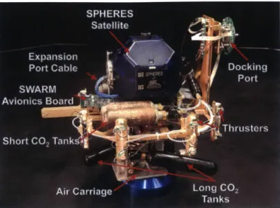
The SPHERES Halo extends the range of possible sensors and actuators that can be operated in this testbed by supplying high speed data processing and increased data storage. The SPHERES Halo is six-port expansion to the SPHERES VERTIGO test facility. As shown in Figure 2-1, the Halo exoskeleton allows scientists to mount and control multiple pheripherals within a single facility. The design is modular so that scientists can test as much or as little as desired during a single test. Such a setup is highly conducive to advancing servicing technologies as it allows researchers to rapidly iterate on both payloads and software in a representative testing environment.
SPHERES
Halo Ports
VERTIGO
(6X)
Avionics
Stack
Figure 2-1: Halo Prototype Hardware that Supports Peripherals On Up To Six Halo Ports
of power and communication lines for operation. This includes " 2X USB 2.0
" Gigabit Ethernet
" Regulated 5V power at 1 A
" Unregulated 12V power at 1.5 A
The Halo flight computer resides within the VERTIGO Avionics Stack (Figure 2-1), which runs a Via Pico-ITX P830 processor. The processor includes 4GB of RAM and two 64GB flash drives running a Linux Ubuntu 10.04 LTS environment. Such a system enables researchers to explore most areas of robotic servicing and assembly, including reconfigurable control, high-precision pointing, inspection and docking. Figure 2-2 shows the variety of payloads already compatible with the SPHERES Halo.
Docking Port
Peripherals
Robotic
ArmO-Peripheral
CMG
Peripherals
Lidar, Optical,
Thermal
Camera
SPeripherals
Figure 2-2: Currently Compatible Halo Peripherals Include Docking Ports, Stereo Vision Cameras, Control Moment Gyro's, Thermo-Imagers, Lidars, and Robotic
2.3
Software Architecture
This section details the philosophy and structure of the HaloCore software platform so that it may be successfully integrated with any code governing the operation of new peripherals. During development, at least seven ideologies drove the design and evolution of the software architecture. Collectively, this software platform, implemented on the VERTIGO Avionics Stack, extends the capabilities of the SPHERES Halo.
" Object Oriented Programming: As shown in Figure 2-3, the HaloCore framework was designed to be as distributed and modular as possible. Since HaloCore is written in C++, the framework improves on the procedural C coding of the SPHERES Guest Scientist Program by abstracting much of the low-level implementation details into object classes. In addition, multiple instances of the same peripheral type (such as docking ports) are easily supported.
" Multi-threading: Threading is critical to the process management of the HaloCore system. Background tasks, communication and telemetry are able to run efficiently and independently of the Guest Scientist's research. Moreover, multi-threading allows peripherals to operate at different control cycles and estimation rates which may be critical to meeting science objectives. Figure 2-6 shows a representative threading scenario run through HaloCore.
" Thread Prioritization: Threading introduces additional complexities such as shared memory and resources. Thread prioritization is employed so that computing resources are fairly allocated between parallel processes in order to achieve the science objec-tives.
" SPHERES Interface: The HaloCore software architecture has been designed to interface with the existing SPHERES facility so that the propulsion and metrology systems of the SPHERES may be leveraged with the operation of any new peripherals. " Robust Data Storage: Data collection and storage is critical for a testbed like
SPHERES because test data is ultimately the science and purpose of the testbed. " Adaptability: The HaloCore framework supports a wide range of present and future
mission objectives.
* Open Source Development Model: The open source software model is intended to generate an increasingly diverse scope of software capabilities for HaloCore. Like the SPHERES Guest Scientist Program, the Halo software is expected to be released online to potential developers to encourage collaboration and research in the satellite servicing field.
object A object B
data communication
Lat]
functions functions
object C
functionsl
Figure 2-3: An Object Oriented Approach to Flight Software Supports Multiple Pe-ripherals Simultaneously
The purpose of the PeripheralCore is to house all necessary functions and variables that are specific to the behavior of the peripheral. Peripherals are anything that attach to and interface with the Halo, such as docking ports and robotic arms. Figure 2-4 shows the diversity of peripherals currently supported through HaloCore. As shown, each payload class inherits from the parent HaloPeripheral class and can be expanded on from there. Each PeripheralCore contains the basic operational code for the payload plus any external science libraries that may be necessary to accomplish the desired science. Other supporting files may be included, such as a class for cameras connected to the peripheral, or a class to manage data storage. These supporting classes provide better organization by grouping related methods (such as those relating to storing results) in a single class. This added abstraction layer makes instantiation of a single (or multiple) peripheral easy and increases the versatility of the presented satellite servicing toolbelt.
HaloCore
OpticsMountCore DockingPortCore ArmCore CmgCore ThermoCamCore OrfCore Core
Science External
science External Science External Science External Science External Science Extenal Science External Libraies Libraries Libraries Libraries Libraries Libraries Libraries Libraries Libraries Libraries Libraries Libraries Libraries Libraries
F--~
Figure 2-4: Current Peripheral Cores Supported By The Halo Software Framework.
Figure 2-5 documents the flow of software beginning with the mainO function that gets called during the C++ code execution. The key take away is that the test project specific code can be written without duplicating background initializations for each new project. Instead, the core Halo code is run automatically and the Guest Scientist's code (denoted with the 'GS' prefix) can be appropriately executed from within the test project source code. The functions in blue are intended to be modifiable by the Guest Scientist based on the intended operational research (refer to Table 2.1).
main() testpcJeegC.cpp
P
Flow of Halo Linux Software
creates object, test, of TestClass
test -> runMain
test inherits HaloGSP
HaloGSP::run Main
> Data Storage Thread
init -- IMU Processing Thread > GSprocesslMU
- Global Metrology Processing Thread >, GSprocessGlobalMetrology
-- Force/Torque Processing Thread > GSprocessForceTorque
-- Gsinit (create peripheral objects)
-- parseParameterFile - GSparseParameterFile
Spheres Thread Halo Thread
GSsetup (initialize peripheral objects, logfiles)
- GScreateCustomThreads (start peripheral threads)
init Background Task Thread >o GSbackgroundTask
-- while loop > GSrunMain > Customizable by
-- GScleanup - GSstopCustomThreads Guest Scientist
shutdown
Figure 2-5: Halo Software Flow Diagram (adapted from [5])
There are several POSIX threads, or pthreads, that always run in parallel during the course of the test, in addition to any peripheral specific threading that may be initialized. These threads support data storage, SPHERES and Halo communication among other tasks. Representative thread execution is shown graphically in Figure 2-6. Threading also introduces a number of complexities related to thread prioritization and shared memory access. Mutexes are used in conjunction with threads to provide greater security and prevent different threads from interfering and perhaps attempting to access the same memory at the same time. The mutexes can be locked and unlocked, and a thread will not continue its process if a mutex is locked and currently belongs to a different thread.
SPHERES Thread Peripheral Thread Peripheral Thread Peripheral Thread Data Storage (UDP Camera) (UDP Motor) (VERTIGO) Thread
User sends request t
Send update to GUI
--
4---User sends request
F Capture image Process image Save image ---Capture image Process undock request
Send update to GUI
---Capture stereo images Process stereo images *-- -- -- - --- - -*-Save images +---F Check image queue Empty image queue Empty image queue
Figure 2-6: Representative Thread Execution During a HaloCore Test Project
2.4
Halo Guest Scientist Program
This section introduces the Halo Guest Scientist Program (GSP) for investigators interested in collaborative research in the field of satellite inspection, assembly and servicing. The Halo GSP extends the capabilities of the existing SPHERES testbed and provides a representative microgravity environment for validating high risk space technologies. This section presents the interfaces to the existing Halo software and provides guest scientists with a framework in which to implement novel algorithms. Two elements of the Halo GSP are detailed herein
- first, the test project specific methods that govern the payload activity and second, the PeripheralCore methods that should be written for any new payloads intended for the Halo.
2.4.1
Test Project Methods
The HaloGSP class allows guest scientists to customize initialization processes, background tasks, parameter parsing, and threads. It also provides methods that the test project accesses, since the testproject class inherits the HaloGSP class. These methods, described in Table 2.1, contain the bulk of the code that dictates what happens during the duration
of the test. These are virtual methods that are declared in HaloGSP and then overwritten and defined as needed in the test projects, allowing the guest scientist to customize their test project.
Table 2.1: Virtual Methods Implemented in a Test Project
Function Description GSinit () GSsetup( GSrunMain() GScustomThreads() GSbackgroundTask() GSparseParameterFile GScleanup() GSparseCommandlineArgs
Initialization method typically used to instantiate object pointers and initialize variables
Runs the initializing methods for peripheral objects and ini-tializes variables
Contains body of the test project outside of any custom threads for each peripheral
Kicks off parallel threads for each peripheral
Used for methods that are to be run in the background, or are secondary to the main test
Parses the parameter file for each peripheral object declared Calls shutdown functions for the peripherals and destructors for the peripheral pointers
Parses additional commandline arguments as it relates to the test project
2.4.2
PeripheralCore Methods
The purpose of the PeripheralCore is to house all necessary functions and variables that are specific to the behavior of the sensor or actuator. Peripherals are anything that attach to and interface with the Halo, such as docking ports and robotic arms. PeripheralCore classes and their methods will be accessed through both calls in the test project code and possibly calls in the HaloGSP code. Here are the essential methods that must be defined in each pheripheralGSP class.
Table 2.2: Necessary Virtual Methods for a Guest Scientist Payload
Function Description
Continued from previous page peripheralGSP(HaloGSP * halo, ... ) inito parseParameterFile 0 startPThreads( sleepPThreads () wakePThreads 0 getSOHBytes 0 shutdown( ~ peripheralGSP()
Constructor method for the peripheralGSP class. The test-project pointer is passed and used to set shared variables. Peripheral ID may also be passed.
Initialization method called within the Gssetp() method within the testproject. Initializes any cameras or processes that should be running; sets certain variable initial condi-tions.
Custom parameter parser which reads the parameter file in-put line by line to set peripheral-specific parameters, prior to the actual initialization of the peripheral. Called within the testprojects GSparseParameterFile() method.
Thread initializer called within the GScustomThreads() method. These threads perform the peripheral science, such as processing images or actuating mechanisms.
Thread sleeper method. Pauses the threads when the periph-eral is not in use to conserver processing resources
Thread waker method. Restarts threads when the peripheral is ready to be used.
State of health method that returns the state information to be passed to the SPHERES.
Pre-destructor method end threads, shut down cameras or processes, ends data storage. This is called at the end of the test, in the GScleanup() method defined in testproject.cpp. Destructor
2.5
Comparison to Existing Robotic Frameworks
It is natural to ask what motivates the creation of the HaloCore software framework when there is no shortage of existing robotics software packages available from the greater robotics community. A variety of platforms were evaluated, chief among them being the Robotic
Operating System (ROS), but ultimately the SPHERES team selected the framework pre-sented in this chapter for three key reasons.
First, the Halo software architecture needs to fall under the open source software license in order to best support remote investigators testing novel space technologies. Open source software benefits from the continued development by multiple users. It also means that HaloCore is expandable and can support any number of new or existing peripherals. For every robotics platform that is open source (such as the Robotic Operating System (ROS), Player and Gazebo) there is a robotics platform that is not (such as VEX or LegoNXT). It was clear from the beginning that commercial packages would not be agreeable in this application.
Second, the Halo software architecture needs to be traceable to future flight systems. SPHERES is a testbed for emerging satellite technologies and algorithms. In order for the testbed to collect valid data, both the hardware and the software must be traceable and scalable to real space applications. Traditional space software teams have full control over their flight operating systems. Some existing robotics platforms may not be stable enough to support the complexities and nuances of spaceflight. It is natural to consider a custom solution, without risking compromising science.
Finally, the Halo software framework needs to be lightweight, clean and simple. Many existing robotics platforms, such as ROS, have a range of capabilities that the Halo software simply does not need. This may add unwanted overhead. Moreover, modern robotics plat-forms are not nearly as constrained by processing and uplink program size as the SPHERES testbed. The HaloCore solution has been trimmed down to the fundamentals, making it an agreeable solution for this application.
ROBOTICS PLATFORMS
Figure 2-7: An Overview of Where the Halo GSP Platform Fits in the Larger Land-scape of Robotics Platforms
Figure 2-7 shows how the Halo GSP system fits into the landscape of robotics platforms. Some robots have already been used in space -Lego Minstorms and Robonaut 2 have flight heritage on the ISS for example. Although the diagram is not comprehensive, it is still clear that the Halo GSP fills a niche of its own as a peripheral agnostic, object-oriented (OOP), software architecture for satellite servicing applications.
SOFTWARE IS
OPEN SOURCI
Gazebo
Player
moos
(Jttr),
RobotC
:ALLY
Chapter 3
Actuator: Flight Hardware Design
of a Rigid Androgynous Docking
Port
3.1
Overview
This chapter describes the flight hardware design and validation of a rigid androgynous docking port for the Synchronized Position Hold and Reorient Experimental Satellites (SPHERES) facility aboard the International Space Station (ISS). The addition of Uni-versal Docking Ports (UDPs) to SPHERES is a critical upgrade that provides the satellites with the ability to dock and undock in six Degreof-Freedom (DoF). This extension es-tablishes the world's first reconfigurable, on-orbit satellite testbed to address many of the challenges of satellite fractionation. These challenges include performing relative sensing and characterization for docking, adjusting to the new system dynamics of the docked ve-hicles, and reconfiguring command and control of the aggregated system. In the near-term, the addition of UDPs will help enable the DARPA Robotic Servicing of Geosynchronous Satellites (RSGS) mission, and in the longer-term they will provide an important capabil-ity for future studies of reconfigurable spacecraft for new mission architectures involving
in-space robotic servicing and assembly.
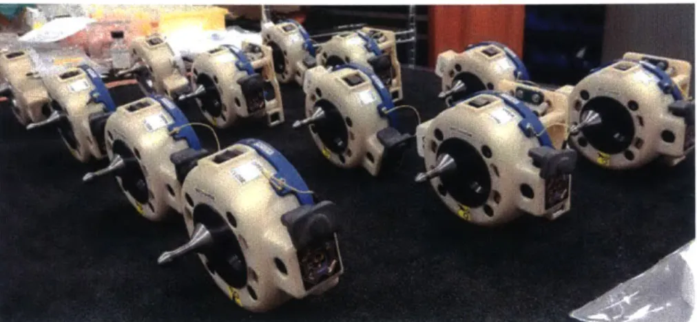
architec-tures (Section 3.2). Specifically, we review the five classifications that traditional satellite docking ports fall under. Then we describe a variety of attributes that may be incorporated into a general docking port design. Section 3.3 presents the first complete iteration of a prototype docking port for use on the SPHERES flat floor test facility. In order to upgrade the prototype technology for space operations, a variety of new design drivers and require-ments were evaluated (Section 3.4) and eventually converged upon (Section 3.5). The flight Universal Docking Ports were first tested in three DoF (Section 3.6) and six DoF (Section 3.7), buying down the risk for the upcoming ISS operations.
Figure 3-1: The Final Flight Design of the SPHERES Universal Docking Port
3.2
Spacecraft Docking Port Design Space
The idea of docking ports for spacecraft is not new. Since the 1960s, dozens of satellite docking ports have been successfully designed, built, and operated in-orbit. At the most fundamental level, the objective of a satellite docking port is to provide a mechanism for rigidly docking and holding two spacecraft together. These agents may be moving relative to one another initially, so the docking mechanism must be able to maintain capture despite forces and torques acting on and across the docking interface.
to the mission. However, all docking ports do share common characteristics that can be useful during the system requirements review phase of development.
3.2.1
Docking Port Classifications
In this subsection, we review standardized docking port architectures as a function of mechanism design and geometry. The list of classifications presented is intended to be comprehensive, and is based on both legacy and proposed designs. Table 3.1 provides one example of each class to illustrate the concept, although other instantiations exist.
Table 3.1: Docking Port Classification Matrix
Classification Description Instantiation
Central Design
The mechanism of a centrally designed Contact
Surface docking port is axially aligned near the
Central origin of the docking face. Typically,
a central design has reduced volume as Loi ing Componnt
compared to the peripheral design.
Peripheral Design Contact
Surface A peripherally designed docking
mechanism will have locking components radially distant from the docking axis. Peripheral
This can boost docking rigidity and
Locking
provide volume for capabilities like mass Component.
or fluid transfer. Simplified Mechanism Designs.
Courtesy of Lennon Rogers [26]