HAL Id: hal-01174120
https://hal.inria.fr/hal-01174120
Submitted on 8 Jul 2015
HAL is a multi-disciplinary open access
archive for the deposit and dissemination of
sci-entific research documents, whether they are
pub-lished or not. The documents may come from
teaching and research institutions in France or
abroad, or from public or private research centers.
L’archive ouverte pluridisciplinaire HAL, est
destinée au dépôt et à la diffusion de documents
scientifiques de niveau recherche, publiés ou non,
émanant des établissements d’enseignement et de
recherche français ou étrangers, des laboratoires
publics ou privés.
A Comparative Study of 3 Body Segment Inertial
Parameters Scaling Rules
Antoine Muller, Coralie Germain, Charles Pontonnier, Georges Dumont
To cite this version:
Antoine Muller, Coralie Germain, Charles Pontonnier, Georges Dumont. A Comparative Study of 3
Body Segment Inertial Parameters Scaling Rules. Computer Methods in Biomechanics and Biomedical
Engineering, Taylor & Francis, 2015, pp.2. �10.1080/10255842.2015.1069600�. �hal-01174120�
A Comparative Study of 3 Body Segment Inertial Parameters Scaling Rules
A. Muller
a,b*, C. Germain
a,b, C. Pontonnier
a,b,cand G. Dumont
a,ba IRISA/INRIA MimeTIC, Rennes, France; b ENS Rennes, Bruz, France; c Ecoles de Saint-Cyr Coëtquidan, Guer, France
Keywords: Body Segment Inertial Parameters; Inverse dynamics; Joint torques; Throwing motion
1. Introduction
Inverse dynamics method consists in retrieving forces from motion capture data. It implies the use of a skeletal model that can be defined as a multibody articulated system. For each segment, Body Segment Inertial Parameters (BSIP) have to be estimated. Without advanced techniques, BSIP are estimated from anthropometric data.
Many papers discussed the influence of the BSIP scaling on the inverse dynamics results (Pearsall and Costigan 1999), (Rao et al. 2005), (Reinbolt et al. 2007), (Wesseling et al. 2013). These comparative studies were realized on gait analysis. However, further investigations remain necessary to extend these results, for example with other movements or for different populations.
The aim of this paper is to present a benchmarking of 3 anthropometric BSIP scaling rules on overhead throwing motion.
2. Methods
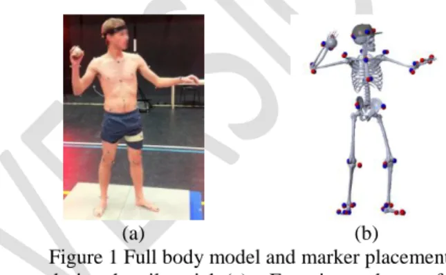
One pilot experiment was performed on a single subject – a 60 kg, 170 cm – in our lab. This experiment was composed of 4 overhead throwing. 40 motion capture markers were placed on the whole body (Figure 1(a)). The motion was recorded at 100 Hz using a Vicon motion capture system. The markers trajectories were filtered using a 4-th order Butterworth low pass filter with a cut-off frequency of 5 Hz and no phase shift. Synchronously with kinematics, ground reaction forces data were recorded at 1 kHz from two force platforms.
The whole body skeletal model used in this study is composed of 21 rigid bodies linked by 17 joints and exhibits 32 degrees of freedom (Figure 1(b)).
The joints coordinates were estimated, from motion capture, with an inverse kinematics method allowing the segment lengths and marker positions to be calibrated (Muller et al. 2015).
BSIPs were estimated using three BSIP scaling rules. Two of them are derived directly from literature ((DeLeva 1996) and (Dumas et al. 2007)). The last one is a hybrid method used by the Anybody™
modelling software (Anybody Technology). The segment masses were estimated using (Winter 1990) and segments were considered as cylinders to compute their moments of inertia. The dimensions of each cylinder are estimated from the mass, the density and the length of the corresponding solid. All the three methods used a uniform scaling.
(a) (b)
Figure 1 Full body model and marker placements during the pilot trial. (a) – Experimental setup for
motion capture; (b) - Model.
The joint torques were computed by solving the dynamical equations. The external forces applied to the model were ground reaction forces and the force applied by the ball on the right hand. The joint torques computed with each scaling method were compared. The analysis pipeline was implemented in Matlab®. SimMechanics was used to solve the inverse dynamics problem.
3. Results and discussion
3.1 BSIP components
Table 1 summarizes the results of the BSIP estimation on the right arm from calibrated model. The 𝑦 axis is the longitudinal axis. The moments of inertia are only given around the 𝑦 and 𝑧 axis as 𝐼𝑥𝑥 and 𝐼𝑧𝑧 have very
comparable magnitudes. These results show large differences depending on the scaling method used. For the mass estimation, relative errors reached 14%. The hybrid method gave significantly different hand inertias, as it modelled the hand as a cylinder.
𝑚 𝐼𝑦𝑦 𝐼𝑧𝑧 Arm Winter 1.62 1.4 12.8 Dumas 1.39 2.4 12.8 De Leva 1.57 3.5 10.2 Forearm Winter 0.93 0.53 5.5 Dumas 0.99 0.81 4.9 De Leva 0.94 0.94 4.5 Hand Winter 0.35 0.1 1.0 Dumas 0.35 1.7 3.6 De Leva 0.35 1.9 3.1
Table 1 BSIP components estimated at the arm, forearm and hand using the three selected estimations
models for a - 58 kg, 170 cm – subject model after kinematical calibration (𝑚 : mass in kg; 𝐼 : moment
of inertia in g.m²).
3.2 Joint torques
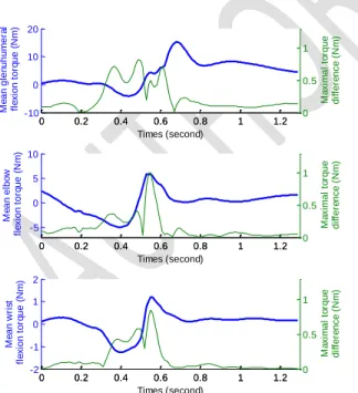
Figure 2 shows the glenohumeral, elbow and wrist flexion torques for a single trial. Mean torque of all the scaling methods and maximal torque differences (differences of amplitude between the 3 scaling methods) are represented. The amplitude of differences was similar from one joint to one another. However, differences relative to the maximal joint torque computed for each joint exhibited very different values within joints.
For the glenohumeral flexion, the relative difference was about 5% whereas it was of 70% for the wrist flexion. In summary, the relative difference increased significantly for distal segments.
Figure 2 Mean flexion torque and maximal torque difference of each scaling method for glenohumeral,
elbow and wrist joints.
Figure 2 only shows a single throwing trial. For the four trials, all joints included, the maximal torque difference was comprised between 0.82Nm and 1.07Nm.
4. Conclusions
The present study aimed at presenting a
benchmarking of 3 anthropometric rules of BSIP scaling. Even if large differences were observed on the BSIP estimation, for the most solicited joints, the inverse dynamics results were poorly sensitive to the BSIP scaling rules. Further investigations remain necessary to extend this benchmarking to more advanced techniques to estimate subject-specific BSIP and assess their validity for motion analysis.
Acknowledgements
The authors wish to thank Anthony Sorel for his precious work on motion data. This study was partially funded by the ANR project ENTRACTE (Grant agreement: ANR 13-CORD-002-01).
References
De Leva P. 1996. Adjustments to Zatsiorsky-Seluyanov's segment inertia parameters. Journal of biomechanics. 29(9), 1223-1230.
Dumas R, Cheze L, Verriest JP. 2007. Adjustments to McConville et al. and Young et al. body segment inertial parameters. Journal of biomechanics. 40(3), 543-553.
Muller A, Germain C, Pontonnier C, Dumont G. 2015. A simple method to calibrate kinematical invariants: application to overhead throwing. ISBS2015, Poitiers, France.
Pearsall DJ, Costigan PA. 1999. The effect of segment parameter error on gait analysis results. Gait and Posture. 9(3), 173-183.
Rao G, Amarantini D, Berton E, Favier D. 2006.
Influence of body segments’ parameters
estimation models on inverse dynamics solutions during gait. Journal of Biomechanics. 39(8), 1531-1536.
Reinbolt JA, Haftka RT, Chmielewski TL, Fregly BJ. 2007. Are patient-specific joint and inertial parameters necessary for accurate inverse dynamics analyses of gait?. IEEE Transactions on Biomechanical Engineering. 54(5), 782-793. Wesseling M, De Groote F, Jonkers I. 2014. The
effect of perturbing body segment parameters on calculated joint moments and muscle forces during gait. Journal of biomechanics. 47(2), 596-601.
Winter DA. 1990. Biomechanics and motor control of human movement. Wiley. 6, 1.
0 0.2 0.4 0.6 0.8 1 1.2 -10 0 10 20 Times (second) M e a n g le n u h u m e ra l fl e xi o n t o rq u e ( N m ) 0 0.2 0.4 0.6 0.8 1 1.2 0 0.5 1 M a xi m a l to rq u e d if fe re n ce ( N m ) 0 0.2 0.4 0.6 0.8 1 1.2 -5 0 5 10 Times (second) M e a n e lb o w fl e xi o n t o rq u e ( N m ) 0 0.2 0.4 0.6 0.8 1 1.2 0 0.5 1 M a xi m a l to rq u e d if fe re n ce ( N m ) 0 0.2 0.4 0.6 0.8 1 1.2 -2 -1 0 1 2 Times (second) M e a n w ri st fl e xi o n t o rq u e ( N m ) 0 0.2 0.4 0.6 0.8 1 1.2 0 0.5 1 M a xi m a l to rq u e d if fe re n ce ( N m )