Publisher’s version / Version de l'éditeur:
Engineering Journal, 43, 10, pp. 81-87, 1960-11-01
READ THESE TERMS AND CONDITIONS CAREFULLY BEFORE USING THIS WEBSITE. https://nrc-publications.canada.ca/eng/copyright
Vous avez des questions? Nous pouvons vous aider. Pour communiquer directement avec un auteur, consultez la première page de la revue dans laquelle son article a été publié afin de trouver ses coordonnées. Si vous n’arrivez pas à les repérer, communiquez avec nous à [email protected].
Questions? Contact the NRC Publications Archive team at
[email protected]. If you wish to email the authors directly, please see the first page of the publication for their contact information.
NRC Publications Archive
Archives des publications du CNRC
This publication could be one of several versions: author’s original, accepted manuscript or the publisher’s version. / La version de cette publication peut être l’une des suivantes : la version prépublication de l’auteur, la version acceptée du manuscrit ou la version de l’éditeur.
Access and use of this website and the material on it are subject to the Terms and Conditions set forth at
Soil problems in mining on the precambrian shield
Legget, R. F.; Eden, W. J.
https://publications-cnrc.canada.ca/fra/droits
L’accès à ce site Web et l’utilisation de son contenu sont assujettis aux conditions présentées dans le site
LISEZ CES CONDITIONS ATTENTIVEMENT AVANT D’UTILISER CE SITE WEB.
NRC Publications Record / Notice d'Archives des publications de CNRC:
https://nrc-publications.canada.ca/eng/view/object/?id=52703858-475b-4077-80f1-ae906baff527
https://publications-cnrc.canada.ca/fra/voir/objet/?id=52703858-475b-4077-80f1-ae906baff527
Ser
TEl
N2Lt2
no. 108
e . 2
BI,DG
1 - l ' , j
\ . '
NATIONAL RESEARCH COUNCIL
CANADA
DIVISION OF BUILDING RESEARCH
SOIL PROBLEMS
IN MININC ON THE
PRECAMBRIAN
SHIELD
By
R. F. Legget and W. I. Eden
Reprinted Ircm The Engineerind Journal Vol. 43 No. l0 November 1960 P. 81-87
TECHNICAL PAPER NO. IO8
OF THE
DIVISION OF BUILDING RESEARCH
OTTAWA
NOVEMBER 1960
A N A L Y Z E D
NRC 6028
PRICE TO CENTS
2,4J-47/6
This publication is being distributed by the Division of Building Research of the National Research Council trs a contribution towards better building in Canada. It should not be reproduced in wlhole or in part, without pennission of the original publisher. The Division would be glad to be of assistance in obtaining such permission.
Publications of the Division of Building Research may be obtained by mailing the appropriate remittance, (a Bank, Express, or Post Office Money Order or a cheque made payable at par in Ottawa, to the Receiver General of Canada, credit National Research Council) to the NaLional Research Council, Ottawa. Stamps are not acceptable.
A coupon system has been introduced to make payments for publications relatively simple. Coupons are available in denominations of 5, 25, and 50 cents, and may be obtained by making a remittance as indicated above. These coupons may be used fol the pulchase of all National Research Council pub-Iications including specifications of the Canadian Government Specifications Board.
R. F. Legger, M.E.I.c.
Director, Dit:ision of Building Research, N atiotwl Research C ounci,l, Ottataa.
W. J. Ed,en,
Nr.E.I.c.
Research Officer, Soil Mechanics Section, Diahion of Building Research,
N atiornl Resear ch C ouncil. Ottaua..
Presented at the E.I.C. Annual General TY/ HEN subsur-face exploration
W wo"k is carried out at a mining property, the soil mantle covering the bedrock is generally considered to be mainly a nuisance, delaying the drilling program and increasing its cost. The driller usually lists the soil mantle simply as "overburden" or "soil" without attempting any de-tailed descrip'tion. Although soil is regarded by exploration drillers, and even by some mining engineers, as an impediment to their work, it can be the over-riding factor in deter-mining the economic feasibility rof a mining property. Two of the most serious failures of mining enterprises on the Shield were due to soil and not to rock problems. The purpose of this paper is to demonstrate that a general knowledge of the properties of soils can be of fundamental im-portance to any mining development program and trhat soil conditions at a mining property can be assessed as a part of the exploration program for the orebody at small additional cost. Soils of the Shield
The present physiography of the Precambrian Shield has been largely determined by the Wisconsin glaci-ation. The entire Shield was covered by a continental ice sheet which re-moved almost all previously existing superficial deposits and many of the softer rocks of the Shield. The drain-age pattem previously existing was disturbed leaving a new and very
young drainage system. The Shield also inherited a sporadic mantle of unsorted glacial till usualll, granular in 'character. On higher ground, gravel deposits such as kames, eskers, and terraces are numerous. Deposits such as these have assisted greatly in the construction of transportation routes in otherwise difficult terrain.
Some parts of the Shield have been subjected to inundation by glacial lakes, and by the sea along the Gulf of the St. Lawrence and along the Arctic coast. In such areas, lacustrine and marine deposits occur which are usually more troublesome than the glacial and glacial-fluvial soils. Most of these soils are compalatively re-cent in origin and have been sub-jected to very Iittle erosion due to the generally poor drainage condi-tions. Because of the poor drainage, pcat dcposits have accumulated on the sulface of much of the Shield: these are now widely l<nown as the Canadian phenomenon of "muskeg". The r,vatcllaid fine-srnined soils of
the Shield can conveniently be grouped into three classes: lacustrine sands and silts, fresh water varved clays and silts, and post-glacial marine clays. The last-named group occurs only in the St. Lawrence low-lands below elevation 700 and alone Hudson Bay, James Bav and thE Arctic coast below elevation 800 ft.l The varved clays and silts have a much wider distribution, being con-fined to former glacial lake basins. They are characterized by a laminar stnrcture consisting, usually, of alter-nating layers of silt or silty clay and clay. Lacustrine silts and sands are also widely distributed in the vicinity of the old glacial lakes, being fre-quently associated with the varved clays.
It is the varved clays that are so frequently encounteled in mining op-erations on the Shield. When dis-turbed they liquefy very easi.ly and so constitute the "mud" that is so often an impediment to Canadian mining development. Unless
care-sor
PROBLEMS
IN MININC
ON THE
PRECAMBRIAN
SHIELD
Soils encountered in mi,ning operations on the Precambrian Shield, are almosl all glacial 'in origin, ranging all, the way Jrom wel,l-d.rained sand and graoel d.eposits, swclt as eskers and. some moraines, to the silts and, clays deposited in glac'ia[lakes. Al,l too many experiences in Canadian mines have shown that the latter cannol safely be regarded, as "jwst mud" to be moved or built upon as the case may be. The character of typical glocial cl,ays is d.escribed., and. the reason for their unwsual pr o p er ties- an ar tif.cial,l,y hi gh natur al moistwr e c ontent-is erplained,. A gainst this backgrownd. examples are gioen oJ satis;t'actory experience in handl,ing such material (as at Steep Rock) and in founding mining structures upon them-(as in the Malartic field), with slnNe constructive reference to troubles thot have been enperienced el,sewhere with soils oJ thi.s type.fully examined, the varved strucfure of these soils may not be recognized but it is usually present even though it does not affect directly the in-stability of the soils when they are disturbed. Many mining engineers will have seen small slides in this fype of soil but its basic instability is most pointedly illustrated by the experiences at the Beattie and the Josephine Mines. These will be sum-marized but only with constructive intent. so that the failures invotrved may form a background for a better
appreciation of the character of some of the soils met with on the Shield, which it is the purpose of this paper to illustrate.
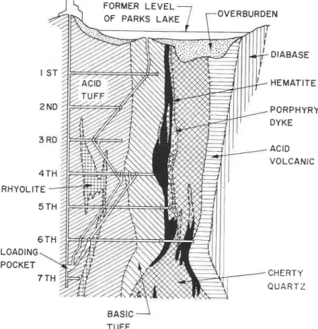
The Josephine Mine: October 1946 The Josephine Mine2 was started in 1941 to win iron ore that had been found in a vertically inclined trody of haematite under Parks Lake in the Algoma District of Northern Ontario. To control underground water, it was decided to dewater Parks Lake and to provide a permanent surface pump-ing installation to take care of local drainage. The sediments in the bot-tom of Parks Lake, consisting of 5 or 6 ft. of organic ooze on the sur-face underlain by 6 or 7 ft. of fine bluish silt, and the remaining depth, varved clay, were left undisturbed after the dewatering operation. A vertical shaft was then sunk at a site adjacent to the lake to a depth of L225 ft. Seven levels were estab-lished at 265 ft., 415 ft., 5L5 ft.,7I5 ft., 815 ft., l0I5 ft., and 1190 ft. respectively below the shaft collar. Fig. 1 shows a vertical section of the mine.
Mining started in November 1945, ore being won by the open stope method, working from the lower Ievels up. It continued until 13 Octo-ber 1946 by which time 173,000 tons of haematite had been extracted. By the end of June, the 6-36 stope had caved up to 30 ft. above the fffth level. Caving continued during July and August and the stope seemed to increase above the fifth level. On 14 September, men working on the fourth level heard considerable cav-ing in the east end of the mine and examination showed that the 36 stope was caving rapidly. By the end of September the cave had opened the stope to a height of 35 ft. above the fourth level. Movements continued and it was soon impossible to follow the progress of the caving in detail. A simple calculation, based on the known expansion of broken ore rela-tive to ore in place, showed that caving could not continue beyond the third level. Despite this a slight de-pression in the Iake bo,ttom was ob-served on 9 October.
This depression had the general outline of the 36 stope and was lo-cated directly over it. As no increase in water was noted underground, op-erations were allowed to proceed. A small quantity of muck was pulled from the 36 stope to check for a fur-ther depression. Between 9 and 13 October, 220 tons of ore were drawn from the stope. As a result, in the early morning of 13 October, a fur-ther subsidence was noted.
At 9.30 a.m., the shift boss found black gelatinous ooze in the east end of the fifth level. It was coming through the broken ore in the work-ings. Immediately salvage work was started on a round-the-clock basis. From 13 to 15 October salvage work continued and a small fow of the ooze continued. At 2.30 p.m., 15 October. men on the fifth level heard a noise similar to escaping air. The cause of the noise was black ooze pouring down the ore pass. Immedi-ately all men were taken out of the mine.
Very shortly, a decided movement was noted in the lake bed. First the original depression settled with the cracks increasing in size. Later, slabs of mud with grass began to move into a central vortex. The flow con-tinued, gradually increasing in vol-ume and speed. About 5 p.*. an old pump barge 30 ft. x 16 ft. x 6 ft. began moving toward the hole. When about 25 ft. from the vortex, it
dammed the flow momentarily and
a hole appeared in the lake bed. The mud cascaded over the edge of the
hole and disappeared. The barge
moved until it reached the hole, tipped, and dived in end first. It wedged momentarily, and as the hole increased in size, disappeared. It could be seen that the walls of the hole were a grey, clayey material. At this point the hole continued to
enlarge rapidly. Air was gulped down
and later regurgitated explosively
throwing muck about 200 ft. in the air. By 5.30 p.m., the hole was 6[] ft. in diameter. Gradually, the move-ments slowed until at 6 p.m. all movement had ceased.
On the following day, a survey showed that the resulting depression covered about 3Ji acres, had a mean depth of 14 ft. and 80,000 cu. yd. had disappeared into the mine. The mud had risen in the shaft to within 30 ft. of the fffth level. It was esti-mated that voids underground were about 85,000 cu. yd. To prevent any
further movement, the mine was
fflled with water. It is believed that most of the material which entered the mine was from the sur{ace layers of organic ooze and ffne silt.
The published account of this
fail-ure raises a number of questions re-garding the cause of the cave-in. Al-though no comment can be made on the behaviour of the orebody in cav-ing, it is almost certain that the prin-cipal lake bottom sediments which filled the mine were typical glacial and post glacial soils of the type that liquefy so quickly following disturb-ances such as that caused by the caving that extended up to the lake bottom.
Beattie Mine: July 1943
The Beattie Mine was located at Duparquet in Northwestern Quebec, abort 22 miles from Rouyn. Mining was started in 193I, the gold-bearing ore being won by a combination of "glory-hole" and underground stoping methods. The "glory-hole" was worked during the summer months and the ore was extracted under-ground during the winter. The "glory-hole" was gradually enlarged each season; by about 1937 it was 1,000 ft. long with an average 100 ft. width. The west end of the Pit was entirely in rock while the eastern end was covered by overburden' The overburden was made up of varved clay overlying waterJaid sand. The stripping of the overburden was ac-complished with a tower dragline and grew progressively deeper with each season. In 1937 a small landslide oc-curred at the easterrr end of the pit, but it did not seriously interfere with
mining operations. Several other
small landslides occurred from 1937 to 1942. About the middle of June 1943, a tremendous earth fow, in' volving several million cubic yards of varved clay, occurred which com-pletely filled the "glory-hole" and all the underground workings. So fluid was the clay that it ran along arr undersround drift over half a mile towards the neighbouring Donchester Mine which had an underground con-nection with the Beattie Mine.3
While production continued at the Donchesterr Mine, steps were taken to rehabilitate the Beattie property. Surface stripping operations were con-tinued as weather permitted to re-m'ove the clay from the Pit. Under-ground the workings were cleared by
sluicing with high pressure water
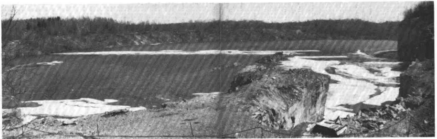
jets and pumping the resulting slurry io the surface. In June 1946, shoftlY after the surface stripping activities began for the season, another large "urth flo* occurred, again completely filling the "glory-hole" and the underground workings' Fig. 2 is a panoramic view of the lake which now oacupies the crater formed bY the two large earth flows. The ,rock wall of the "glory-hole" appears on the light of the photograph.
develoP-ments at important mines have one feature in oomm,on - the sudden liquefaction of soil which flad ap-peared to be reasonably solid material. This property of soils is well ,recog-nized in modem studies of soils and is generally designated as high sen-sitivity.
Modern Soil Studies
The scientific study of soils, called soil mechanics, is now a well recog-nized part of the practice of civil engineering. Although only about a quarter of a century old as an organ-ized discipline, soil studies have been canried out throughout the whole his-tory of modern civil engineering but only by individuals working alone wrtil about 1925. Today, technical journals and excellent text books bring to-gether in convenient form modern knowledge of the character and be-havior of soils as used by the engin-eer. A selection ,of recommended texts is listed at the end of this paper.
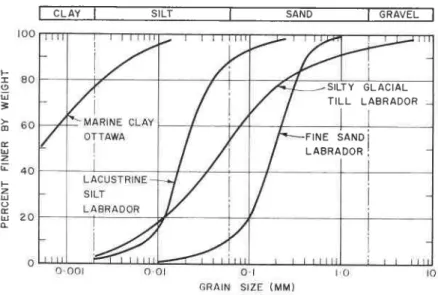
The accurate determination of soil types is a first step in the proper en-gineering study of soils. This can be approached by investigating first the distribution of different size soil par-ticles which rnake up the soil mixture. Fig. 3 is an illustration of the way in which the mechanical analyses of soils can be graphically represented. Cumu-lative curves have been plotted for a silty glacial till, a uniform sand, a lacustrine silt, and a marine ,clay. Ilechanical analyses of soils are car-ried out first by sieving, and then by a sedimentation process for particles smaller than No. 200 sieve.
As soil studies have progressed, the significance of mechanical analyses as a means of distinguishing soils has de-creased because the properties of im-portance in the engineering use of soils are not always related directly to mechanical composition. "Indicator tests" have therefore been develooed to illustrate the reaction of the ioil particles with varying quantities of rvater because, as can well be im-agined, it is the variations in the three-phase air-water-soil mixture that is significant in determining the be-haviour of soils. The indicator tests normally conducted are the deter-mination of the natural water content and the "Atterberg limits".
Atterberg limits are given by two tests designed to indicate the plas-ticity characteristics of cohesive soils. Such soils can exist in three states: liquid, plastic or solid. The liquid limit, as determined by the Atterberg melhod, is the water content at the change from the plastic to the liquid state as determined by an admittedly arbitrary but simple and satisfactory test procedure. The plastic limit is
F O R M E R L E V E L O F P A R K S L A K E
t s T
4 T H R H Y O L I T E 5 T H 6 T H L O A D I N G P O C K E Tthe corresponding water content de-fining the change from the plastic to the solid state and is determined by an even simpler test. The difference between the two water contents is de-fined as the plasticity index. The inter-relation of the indicator test results and their use in distinguishing soil types is well shown by the simple but very useful diagram reproduced as Fig. 4.
Procedures for all of these tests have been set out in ASTM Stand-ardsla the test can be done ,at small cost and with a minimum of equip-ment. Beyond the indicator tests, there are now laboratory tests that determine the mechanical strength of soils either in their natural or in a disturbed state. The most important mechanical pilopefty is the ,shear strength of the soil. This can be de-termined, with a reasonable 'degree of accuracy for cohesive soils, by means of unconfined oompression tests conducted upon ,cylindrical soil samples carefully preserved so as to be as close as possible to their original condltion and moisture con-tent when tested.
Of special importance for the fine-grained soils encountered on the Shield is the relation between the natural water content of a soil and
7 T H
Fig. I Shaft section of Josephine Mine (after Gallie, 1947)
O V E R B U R D E N D I A B A S E H E M A T I T E P O R P H Y R Y D Y K E A C I D V O L C A N I C C H E R T Y Q U A R T Z
its Atterberg limits. This relation can be expressed in a number ,of ways. One of the m,ost common methods is to use the "liquidity index". This is expressed as:
Wn-PL
T T :
-LL-PL where LI: liquidity index
Wn:natural moisture content Ll:liquid limit
PL:plastic limit.
If the liquidity index of the soil is greater than unity, the soil will have a natural water content hieher than its liquid limit so that it ivould be expected to be in the liquid state. Much of the fine-grained soil found on the Shield has a liquidity index considerably greater than one and yet it is to all appearances in a per-fect'ly stable plastic condition. The appearance is deceptive, however, since the soil is inherentlv unstable. the excess of water being hlld in wha[ may be called an internal microscopic honeycomb structure, formed by minute soil particles during the oourse of sedimentati'on. It follows that, if such soils are disturbed from this natural but inherently unstable eondi-tion, the soils will lose their natural character and liquefy in a very short period of time, with results that can
be disastrous.
This high liquidity index does not require a laboratory for its detection since it can be readly daected merely by taking a sample of the undisturbed soil and moulding it between the fingers. The excess moisture will soon make itself evident by the dramatic change in consistency between the un-disturbed and remoulded clays. This is a simple field test that should therefore be familiar to every mining engineer engaged in work on the Shield. If he encounters soils with a high liquidity index he should im-mediately take steps to have proper soil studies made so that danger may be avoided and the natural character-istics of the soil used to good ad-vantage.
Buildings at Malartic
As an illustration of what a care-ful but relatively simple soil study can do, there may be mentioned the design and construction of buildings for the Malartic Goldfields mine at Halet, Quebec. Those who know the clay belt of northem Ontario and Quebec will be familiar with the numerous foundation problems that have developed with buildings con-structed directly upon the claY of this area, particularly if loads have been heavy. With such examples as a guide, the consulting engineer tro Mal-artic Goldfields Ltd. (E. H. Blonson) consulted the senior author while he was on the staff of the University of Toronto and so was able to under-take such special soil studies. An in-vestigation was made of the soil con-ditions at the site of new mine build-ings that were planned. Eighteen simple auger borings showed that rock level was generally about 35 ft. be-low the surface so that it could be used for the support of extra heavy
loads. The overlying soil had a high liquidity index but at the same time had a reasonable shear strength if not disturbed. Most of the founda-tions for the necessary buildings were therefore designed as spread footings using a safe bearing capacity for the soil as determined by shear tests; the heavier loads were carried to rock by means of 235 end-bearing piles' No real problems were encountered during construction and the buildings have continued to serve satisfactorily, in contrast to other buildings not very far away from the site, constructed upon exactly the same type 'of clay but without the benefit of preliminary soil studies.
Experiences at Steep Rock Lake As a further example of what can be done by the application rof soil studies to mining development, there may be mentioned the experience gained with the development of the g,reat iron mine of Steep Rock Iron Mines Ltd. In 1943 and 1944 Steep Rock Lake, with an area of about l0 square miles was drained by pumping, following completi'on of a major river diversion project. The bed of the lake consisted of varved clays to depths up to about 150 ft. with liquidity indices up to 1.5. The instability of this vast deposit of soil is well shown in Fig. 5 showing the "stream" of soil which flowed down a relatively flat slope after being shaken out of a dragline bucket in which it had been excavated in the form of a tough, sticky but coherent mass. All the soil surrounding the areas that had to be cleared for open-pit work-ing was characterized by correspond-ing potential instability.
The mine management suPPorted fully the idea of careful soil studies'5 These demonstrated that, if
undis-turbed, the soil could be trimmed to slopes that would be stable and safe' Extensive test boring, soil sampling, and soil testing showed that, despite the wide exteqt rof the soil deposits to be dealt with, there was a reason-able degree of uniformity to soil properties that permitted over-all slope designs to be plepared. Basic-ally the method used was to trim the excavated soil to a slope of I in 3, limiting the vertical height of each slope to 20 ft. A horizontal berm, the width depending on the shear stlength of the soil, was then excav-ated, and graded gently away from the slope so that drainage would not reach the erodible face of the slope but would be collected in ditches at the back of each berm and led away under constant control. The most striking example of this general design was the Hogarth Barrier, a natural dam 160 ft. high consisting entirely of the unstable soil already described, trimmed as indicated, stretching across the Middle Arm of the lake. It served to isolate the area of the so-called "A" ore-body which was then excavated in open pit to a dePth of rover 500 ft. below the original lake level, and 200 ft. below the top crest level of the barrier which was, originally, the level of the bottom of the lake.
It must be stressed that the figures given for the slopes used at SteeP Rock are of relevance only for sroils with the exact characteristics of those encountered in the bed of Steep Ro'ck Lake. These were based on a large nurnber of relatively simple shear tests on undisturbed soil samples. The Steep Rock experience, however, il-lustlates 'uvhat can be done, even in a lake-bed filled with unstable soil, by the application of the scientific apploach to soil, coupled with a full
apprecration on the part of manage- major soil variations flom a study samples, ,obtained as indicated, must ment of the vital importance of even of aerial photographs and identify be used for acrcurate determination the simplest precautions in maintain- land forms that may reveal soil con- of bearing capacity and other neces-ing unsta'ble soil in its natural state, ditions. sary strength characteristics for all and in controlling all ground and A test drilling program is naturally cohesive (fine-grained) soils.
surface water in the vicinity. the most positive way of determining
soil conditions. If overburden is pre- Some Soil Problems in Mining
Soil Studies in Exploration Work sent over an orebody, the exploratory Some of the major soil problems _ In_ the exploration stage of mining holes necessary for ore exploration that may be encountered in mining development, geophysical surveys may must be cased down to rock. Durng operations on the Precambrian Shield be conducted, air photographs ob- the sinking of h,oles to rock level, may be briefly noted in conclusion to tained and studied, and a 'test drill- soil samples that provide definite in- illustrate how the application of soil ing p-rogram initiated. All these ap- formation on soil properties can read- mechanics studies may assist in the proaches are also commonly used in ily be obtained, with very little delay, successful development of a mining soil exploration work. In mining de- by forcing split-barrel o,r Shelby soil property. Table I presents t{ris infor-velopment, therefore, it is possible samplers into the undisturbed soil. mation in summary form in relation to_ combine preliminary soil studies, These samples can then be subjected to the main types of soil that may be where soil is present in any significant to the simple indicator tests already encountered.
quantity, with normal mining explorra- mentioned and can give a good gen-tion at' little, if any, extra cosi and eral picture of subsu"r.face ioit
"oiai-
Roads: The first construction work with the expenditure of very little tions. These could
extra time, provided only that soil later by more detai exploration is recognized as an es- sary. Observations sential part rof the preliminary pro- completed drill ho
gram. invaluable informa
All the geophysical methods norm- water conditions. I ally used in the search for ore, with ized that only by n the natural exception of the use of disturbed soil saml the Geiger counter, can be used to conditions be deter indicate depths to bedrock and sig- acy, sediment in nificant changes in the character of never completely : overburden. Seismic methods are par- times quite definit, ticularly applicable to determinations In the case of gl of depths to bedrock so that in areas ful record of the such as that in the vicinity of the drive in the sample Beattie Mine it would be possible to density and strengl determine well in advance of mining penetrated. The be operations whether there is a rock be determined, at I barrier between any body of open ary way, f'rom the water such as Duparquet l-ake and lequired to drive the area to be developed for mining barrel sampler I purposes. Aerial photo interpretation weight of hammer is now an established technique with Even in the case ol an appreciable literature of its own driving record wil (some reference to which is made indication of the in the accompanying bibliography). In soil fo'rmation and many cases it is possible to distinguish its strength ch,
of overcoming this problem is by the selection and use of non-frost sus-ceptible materials for road building.
F I U
=
(Il (r U z. L F z r o E U &Fig. 3 Grain-size distribution of four soils
Deep excaoations: In sinking shafts or stripping overburden from open pits, deep excavation in soils may be necessary. In granular soils ex-cavation work can proceed, only if success is first achieved in controlling groundwater. Slopes will be stable rvhen cut to the angle of repose of the material. For deep shafts, ground-water can be controlled by several methods including dewatering by u'ell points, freezing, grouting, sta-bilization by electroosmosis, or chem-ical grouting. The choice of method will depend largely on the exact soil conditions.
For fine-glained soils, in addition to the control of water in any pervi-ous strata encountered, the shear strength of the soil must be
consid-S I L T Y G L A C I A L T I L L L A B R A D O R
F I N E S A N D I
I
5 0
te
I r 4 0g
x
lrl oz 3 0
F()
F q 2 0 J o.t o
I N O R G A N I Czo
J I L I 5ered. It can be shown that a srhaft in cohesive soil, even though adequately shored, should not proceed beyond a depth defined by Dc:Nc.(S"/'y), where Dc is the critical depth, Nc is the coefficient depending on the dimensions of trhe shaft (9 for deep shafts), 'y is the density of the clay, and S" is the undrained shear strength.T If an open excavation pro-ceed,s beyond this point, the bottom will probably blow in. Special con-struction methods will then be ne-cessary to complete the shaft to the desired depth. Side slopes and trhe shear strength of the soil will limit the depth to which open excavations for pits can be carried. In all cases of deep excavation in soils, a test boring and soil testing program con-ducted by a cornpetent authority can lead, to safe design and construc'tion methods. When the soils involved are sensitive, it is imperative that the risk of failure be kept to a minimum. Tihis can be done by the careful applica-tion of soil mechanics.
Foundations for buildings and sur-face installatdoru; As the experience at Malartic Goldfields Mine has shown, it is quite possible to found buildings directly even on sensitive soil. With adequate soil information available, safe designs can be deter-mined from the shear strength and compressibility characteristics of the
40 50 60
L I Q U I D L I M I T ( L . L . ) - % Fig. 4 Casagrande's plasticity chart
soil. If the soil conditions are diffi-cult, pile foundations, to transfer loads to bedrock, may be the only satis-factory solution. In keeping with the over-all and always dominant require-ment that soil should be disturbed as little as possible from its natural state, piles should, only be used when pre-liminary soil studies have shown them to be absolutely necessary. At Mal-artic, they were useful in conveying the heaviest loads directly to bedrock so that the necessary disturbanoe of the varved clay by driving was imma-terial. Pile driving in suoh clays usu-ally tends to liquefy them to a certain extent so that, in extreme cases, it is possible actually to reduce the bear-ing capacity of a buildbear-ing site (on sensitive clays) rather than to in-crease it by the driving of piles. The use of piles should, never be con-sidered without first obtaining ex-pert advice on the necessary founda-tion design.
Stockpiles: It is sometimes neces-sary to build up large stockpiles of ore or other material on a mining property. The loads so placed on the underlying ground can be con-siderable; there rhave been many in-stances of failure of underlying ground. If this merely disturbs the ground under the pile the conse-quences may be serious enough, but soil failure will always affect a
con-siderable area around a pile so that adjacent structures may ibe nloved or even destroyed. Soil studies are therefore an essential preliminary to the start of any stockpiling on any surface other than solid rock.
Tailing dams: Conespondingly, in ore processing operations, it is some-times necessary to store the tailings from mill operations. If this cannot Fig. 5 Excavated silt flowing after being-
dumped from dragline bucket W E A K L Y P L A S T I C I N O R G A N I C C L A Y S C O H E S I O N L E S S S O I L S M E D I U M P L A S T I C I N O R G A N I C C L A Y S H I G H L Y P L A S T I C I N O R G A N I C C L A Y S I N O R G A N I C S I L T S O F H I G H C O M P R E S S I B I L I T Y , O R G A N I C C L A Y S L E G E N D O F I N D I V I D U A L T E S T S O N C H A R T O S T E E P R O C K L A K E o V A L D . O R A M A L A R T I C I A M O S ! U R A N I U M C I T Y I M O I S I E R I V E R M E D I U M P L A S T I C SILTS tr NruO O R G A N I C C L A Y S LF{KI 4KR<r
TABLE I
Soil Problems in Relation to Mining
Condition Road Construction Shaft Sinking Adequate shoring
Adequate shoring and control of seepage water (quicking)
Deep Open Excavations Building Founda,tions Well drained gravels
and sands Saturated gravels and sands
Saturated glacial rill
Saturated silts and sandy silts
Muskeg
Drainage will control frost action
Mav be frost suscen-tiblir in which case' drainage will not pre-vent frost heave
Adequate shoring and control of seepage if anv. In extreme deiths, a possibility of bottom heave
Must be removed en-tirely or positively drained
Drainase alone will not controllrost action. Adequate non-frost-susceptible base must be used.
Frost susceptible. Safe height of fill limited by shear strength
Route must be care-fully selected to take advantage of most woody peats. High fills may require com-plete removal of peat. Grassy bogs if crossed must be excavated
Adequate shoring-con-trol of seepage pres-sure vital to orevent quick conditi-ons Adequate shorins-con-trol of seepage wi,ter-depth of open shaft limited by shear strength
Must be removed and
site drained founded on peat-must,Buildings should not be be removed from site
Possibility of settle-ment under vibratory Possibility of settle-ment due to vibratorv loads and drawdown bf water table
Control of seepage water. Side slopes: angle of repose Control of seepage water. Side slopes: lft: I except for ex-tremely deep excava-tions or where tiII is loose
Control of seepage water and pressure vital. Side slopes subject to erosion
If till is dense. a bearing capacity of 5T/sq ft, can be expected
Little oossibilitv oi settlement excebt where till is very loosti Bearins capacitv limited. Subiect toiome settle-ment under static loads and drawdown of water table
Saturated silty clays and clays, varved clays
Control of seepage water. Depth of ex-cavation dependent on side slopes and shear strensth. If LI exceeds 1, failure can be disastrous
Bearing capaeity limited by shear strength and consolidation character-istics-heavy stockpiles subject to base failure
be done in a natural depression, it is common practice to form "earth dams" with the tailings, gradually in-creasing the height of these dykes as storage increases. Care in the prepara-tion of the site of such an artificial dam will always be necessary; study of the mechanical properties of the tailings, as deposited, will always be advisable since adequate dimensions for the cross-section of the dyke can then be determined, and precautions taken against possible slope failures that can &rave serious consequences. Conclusions
The object of this paper has been to indicate the nature of some of the soil problems that have been en-countered by the Canadian mining industry, with special reference to the Precambrian Shield. Paradoxic-ally, although rock conditions on the Shield are good on the whole, some of the most treacherous of all soils have been formed from these rocks. The drainage on the Shield is gen-erally poor. The fine-grained soils usually have a lorv strength, high
com-pressibility characteristics, and high sensitivities. Because of their high sensitivity, failure in fine-grained soils can have disastrous consequences.
During the exploration phase of a mining development, with slight ad-ditional expense, information can be obtained from which it is possible to anticipate generally the problems that may be encountered with soils. If bad or unusual soil conditions are in-dicated, expert assistance in desigr and construction should always be obtained. Continuing attention to all soils encountered in mining opera-tions, however, on the part of all responsible for development work, is the best iruurance for avoiding trouble. Recognition of soils as ma-terials that can be tested and used to good advantage if only their pro-perties are known can furn even the most serious potential soil problems into an engineering challenge. References
1. Glacial map of Canada. Ttre Geological Association of Canada. Toronto. 1958. 2. Gallie, Alan E., Mining methods and
costs at the Josephine Mine. Can. Inst. of Mining and Metallurgy, Bulletin No, a127, November L947. p. 589-636.
6. Radforth, N. W., Suggested classifica-tion of muskeg for the engineer. Enei-neering Journal, VoI. 35, No. 11, Novefr-ber 1952.
7. Bjerrum, L., and O. Eide, Stabilitv of strutted excavations in clay. G€otech-{r-iq}!e, Vol. 6, No. 1, March 1956. p. 32-47.
Bibliography
1. Hvorslev, J, M. Subsurface ExDloration and Sampling of Soils for Civil Enei-neering Purposes. Amer. Soc. of Cii/il Engineers, Committee on Sampling and Testing. Edited and print€d bv Water-lvays Expellment Station, Vicksburg, Miss. 1949. 521 p.
2. Lueder, D. R. Aerial Photographic In-terpretation; Principles anti Applica-tions. New York. Mccraw-Hill: - 1959. 462 p.
3. MacFarlane, I. C. Guide to a Field Description of Muskeg. National Re-search Council, Associate Committee on SoiI and Snow Mechanics, Technical Memoranduf,n No. 44, Ottawa. 1957. 4, Terzag}]L I{., and R. B. Peck. SoiI
Me-chanics in Engineering Practice. New York, John Wiley and Son, 1948. 566 p. 5. Tschebotarioff, G. P. Soil Mechanics.
Foundations and Earth Structures: ari introduction to the theory and Drac-tice of design and construction. lst ed. New York, McGraw-Hill, 1951. 655 D. 6. Guide to the Field Descrintion of Sciils for Engineering Purposes. National Re-search Council, Associate Committee on SoiI and Snow Mechanics. Technical
Memorandum No. 37, Ottawa, 1955. Etr
A list of all publications of the Division of Building Research is available and may be obtained from the Publications Section, Division of Building Research, National Research Council, Obtawa, Canada.