Publisher’s version / Version de l'éditeur:
Vous avez des questions? Nous pouvons vous aider. Pour communiquer directement avec un auteur, consultez la première page de la revue dans laquelle son article a été publié afin de trouver ses coordonnées. Si vous n’arrivez pas à les repérer, communiquez avec nous à PublicationsArchive-ArchivesPublications@nrc-cnrc.gc.ca.
Questions? Contact the NRC Publications Archive team at
PublicationsArchive-ArchivesPublications@nrc-cnrc.gc.ca. If you wish to email the authors directly, please see the first page of the publication for their contact information.
https://publications-cnrc.canada.ca/fra/droits
L’accès à ce site Web et l’utilisation de son contenu sont assujettis aux conditions présentées dans le site LISEZ CES CONDITIONS ATTENTIVEMENT AVANT D’UTILISER CE SITE WEB.
Internal Report (National Research Council of Canada. Division of Building Research), 1960-06-01
READ THESE TERMS AND CONDITIONS CAREFULLY BEFORE USING THIS WEBSITE.
https://nrc-publications.canada.ca/eng/copyright
NRC Publications Archive Record / Notice des Archives des publications du CNRC :
https://nrc-publications.canada.ca/eng/view/object/?id=978089cf-9eb1-4bcd-b534-b9d634277605 https://publications-cnrc.canada.ca/fra/voir/objet/?id=978089cf-9eb1-4bcd-b534-b9d634277605
For the publisher’s version, please access the DOI link below./ Pour consulter la version de l’éditeur, utilisez le lien DOI ci-dessous.
https://doi.org/10.4224/20338170
Access and use of this website and the material on it are subject to the Terms and Conditions set forth at
Evaluation of the Setchkin Method for determining the ignition properties of plastics
NATIONAL RESEARCH COUNCIL CANADA
DIVISION OF BUILDING RESEARCH
AN EVALUATION OF THE SETCHKIN METHOD
FOR DETERMINING THE IGNITION PROPERTIES OF PLASTICS
by
J 0 Ro Jutras
ANAL YZED
Internal Report Noo 198 of the
Division of Building Research
OTTAWA
The examination of a test procedure by what is now
commonly known as a round-robin test program is a well-established practice0 Attention is usually focussed on a particular problem
area, and the exchange of experience between laboratories is almost always useful and sometimes stimulatingo The work carried out by the Fire Research Section of the Division in the course of a
round-robin program on the measurement of certain properties of plastics is now reportedo The author is a physical chemist and a research officer in the Fire Research Section having a special interest ih the chemical changes in materials produced by heating such as may occur in fireso
Ottawa June 1960
No Eo Hutcheon Assistant Director
AN EVALUATION OF THE SETCHKIN METHOD
FOR DETERMINING THE IGNITION PROPERTIES OF PLASTICS by
Jo Ro Jutras
10 INTRODUCTION
In
1955,
Committee D-20 on plastics of the American Society for Testing Materials recognized the need for a suitable method of determining the ignition properties of plastic materials o Its subcommittee on thermal properties was therefore charged with the responsibility of studying the problem and of developing a testing procedure which could later be considered for adoption as a standard0A survey was first carried out of the literature on existing methods which might find application in the field of plasticso Of the two papers found to be of
parti9ular"slgni-ficance, the one published in
1949
by Setchkin(1)
deserved special considerationo SetchkinUs work was later used by the subcommittee as the basis in preparing a tentative testing procedure by which flash- and self-ignition temperatures could be determined using a constant temperature method0Various ャ。「ッイ。エッイゥ・ウセ through their representatives on
-,
the subcommittee, were then asked to participate in a round-robin series of tests aimed at evaluating the suggested procedureo The Division of Building Research, National Research Council of Canada? is represented on the subcommittee by Mro JoEo Hanna of the
Canadian Government Specifications Board o Since the Fire Research Section of this Division had recently acqUired a Setchkin Ignition Apparatus to study the ignition characteristics of solid materials
in general, the Division was ーセ・。ウ・、 to participate in the round robin a10ng with six American organizations:
1& E.I. duPont de Nemours and Co., Inc., Wilmington, Delaware.
2. Rohm and Haas Co.,
Bristol, Pennsylvania.
3.
The Dow Chemical Co., Midland, Michigan4.
Monsanto Chemical Co., st. Louis, Missouri.5.
International Business Machines Corporation, Endicott, New York.6. National Bureau of Standards, Washington, D.C.
2. SCOPE
It was the intention in this series of tests to use two main ゥセゥエゥッョ characteristics of plastics for the comparative evaluation of the proposed testing procedure. The first is the flash point or flash-ignition temperature, that is, the lowest temperature at which the specimen develops combustible gas at a sufficient rate to form an ignitable mixture with ambient air. The other is the self-ignition temperature or the lowest tempera-ture at which, in the absence of an igniting source, self-heating of the specimen will proceed at a sufficient rate to carry the ignition process to visible ignition (flame or glow).
For the round-robin tests, five plastic materials were selected by the subcommittee, and appropriate quantities of each were distributed to the seven participating laboratories with instruction that they be tested according to the suggested method.
l. A
2. 1'>
3.
A4.
A3
-The materials selected were:
polyamide: Zytel 101, lTC-10, lot .:217J polyester-fiberglass: sample .: o. \ZGセIMdXUVc
polystyrene: styron 666 :::27 Jlear 71, lot P1373 polyethylene: Polyethylene 61011 ZャRセN
no ,
1(TvI.I.=50), Zセ。エ」ィ 70572"3
5. An ethyl cellulose: Ethocel 880-1 27 セGdエN 2, lot G08L
t ,
2-10,All of the materials were s'upp I Le d セ⦅[^ャ »e L'lot :i:'oX'''1 XxccセMGエ
for the pol;yester-fiberglass which consisted oX a 1/16-iYlch t.hi c k sheet that had to be cut in 3/4-inch squa:re<.(JCCS for -i.;hCCC.Tl;.
3. EXPERIMENTAL DETAILS 3.1 Apparatus
The apparatus described in the metihod of test is
essentially that developed by Setch1=in (1) except lor minor
modi-fications in the method of s us pen sLon of the [NNSセGGGjcゥャZャ・ョN It is shown 'vvi th other required instrumentation in I'ig, 1. 'I'hi.s same apparatus is also used by the American SP」ゥ・j」セB for i1c;Jt"illi .ator-ia Ls in the determination of the non-combustii)le cha ract.er or cLementary
materials (2) and is now available c oame rcLal Ly Dc,i.;hc ャiセ」エ」ィGZZゥョ
Self-Ignition Apparatus for Solids" (3).
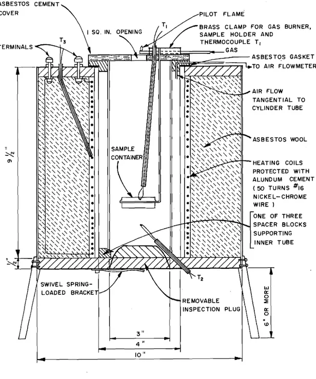
3.1.1 Furnace
The f'urria c e (Fig. 2) consists prir1aril:! of' tcw 10-inch-long refractory tubes of different di.arnete.r arranged c oax.La lLy with axes vertical. The inner tube, i'vith a 3-inch ;;ore, forms the;
combustion chamber proper, The ovter tube, ','lith a 4-inch bore, serves as furnace tube and is heated electrically by means of an electric coil of 16-gauge Br-own arid セSィ。イー・ nicl:el-chrome wire
wound around the exterior of the tube. The coil is protected with alundum cement; asbestos wool provides the required insulation.
The space between the two tubes is used for circulation and heating of the combustion air which is admitted tangentially at a controlled rate near the top of the annular space. To provide access of this pre-heated air to the combustion chamber, the inner tube rests on spacer blocks at the bottom of the furnace.
The cover, made of transite, has a circular opening (1 1/8 inch in diameter) for the passage of smoke and gases, and
is provided with a pilot flame burner for flash-point determinations.
An inspection plug at the bottom of the furnace can be removed for the cleaning out of residues that may accumulate during tests. 3.1.2. Thermocouples
Three chromel-alumel (0.020 inch) thermocouples are used for temperature measurements: thermocouple Tl at the centre of the sample to detect any self-heating within the sample; thermocouple T2 below the sample to record the temperature of the pre-heated air; and thermocouple T
3 on the heating coil.
In this series of tests, all three thermocouples were connected to a multipoint recorder. Temperatures at thermocouple Tl were recorded at 8-second intervals; temperatures at the other two thermocouples at 16-second intervals.
3.1.3. Sample container
The sample container consists of the bottom half of a 1/2-ounce metal salve container, style 100. It is held in a ring of 1/16-inch stainless steel welding rod welded to a length of same rod extending through the cover of the furnace (Fig. 3).
3.1.4. Flowmeter
The rate of air flow through the furnace is controlled by means of a Brooks Sho-rate 150 rotameter equipped with a constant differential relay to maintain a constant flow rate irrespective of line pressure variations. The "Tru-taper" tube (size 6-15-2) of the rotameter is calibrated directly in units of 0.02 cubic foot per minute over a range extending from 0.06 to 0.80 cubic foot per minute. Air flows can thus be adjusted to the closest 0.01 cubic foot.
3.2. Procedure
It has been established by C.R. Brown (4) that when operating under dynamic conditions for the determination of ignition temperatures, the rate of air flow past the sample can appreciably affect the end results. Consequently, where minimum ignition temperature values are desired, optimum air flow conditions have to be predetermined. It is usually found more expeditious, particularly when a constant temperature method of test is used, to carry out these preliminary determinations by running quick tests under rising temperature conditions. In the test method, it is therefore necessary to proceed in a step-by-step manner whereby:
(i) first, the optimum flow of air ,is determined by running tests at various air flows under rising temperature con-ditions using a rate of air temperature (T2) increase of ,approximately 11000F (or 600°C) per hour;
(ii) secondly, approximation of the ignition temperature is obtained by running tests at the optimum rate of air flow under rising temperature conditions using a rate of air temperature (T2) increase of approximately 600°F
(or 300°C) per hour, and
(iii) finally, the minimum ignition temperature is determined under constant temperature conditions.
302010 Determination of optimum rate of air flow
30201.10 Flash-ignition temperature.- Approximately 3 grams
±
0.5 grams of the plastic material is placed in the furnace and the air flow is set to give a linear air velocity of 5 feet per minutepast the sample. The variable transformer controlling the current through the heating coil is then adjusted to provide a rate of rise in temperature at thermocouple T
2 of approximately 11000F (or 600°C) per hour and the pilot flame is lit.
The recorded air temperature (thermocouple T2') at which the temperature at the centre of the sample (thermocouple Tl) starts to rise rapidly is reported as the approximated flash-ignition temperature at this particular rate of air flowo
The procedure is repeated at linear velocities of flow of 15 and 20 feet per minute and in each case the flash points are noted o The rate of air flow at which the lowest flash-ignition temperature is obtained is referred to as the optimum flow rateo
3.2.1.20 Self-ignition temperatureo - The same procedure as given in 3.20101. is repeated without the pilot flame and the optimum flow for determining self-ignition temperature is obtainedo There are cases, however, where it is セッエ possible during the rising temperature run to reach ignition because some plastics, eog o polystyrene, boil away before self-ignition can take place •
.
302020 Approximation of ienition temperature3.202010 Flash-ignition temperature. - With the sample of material in the furnace and the air flow set at the optimum flow found under
SPRセQNQNL the electric current is adjusted to provide a rate of rise in temperature at thermocouple T2 of approximately 600°F
(or 300°C) per hour and the pilot flame is lit. The temperature T 2
7
-at which the temper-ature -at the centre of the sample (thermocouple Tl) starts to rise rapidly is reported as the approximated flash-ignition temperatureo
30202.2. Self-ignition temperatureo - The same procedure as
in
3.20201. is repeated in the absence of an igniting source and the approximated self-ignition temperature is obtained.302.30 Determination of minimum ignition エ・ュー・イ。セオイ・
3.203.1. Flash-ignition エ・ュー・イ。エセ・ッ - With air flow rate set at the optimum flow the furnace temperature (T2) is stabilized within 20°F (or 10°C) below the approximate flash temperature found in 302.201. The sample is then introduced in the furnace and the pilot flame lit.
If ignition occurs, the same procedure is repeated using a new sample at a temperature 20°F lower and so on until no
ignition is detected over a minimum period of 30 minutes. When a temperature T2 is thus reached at which no ignition occurs, a second run is conducted at the same temperature to ascertain that this 'is truly below the ウ・ャヲMゥァョゥエゥッセ temperatureo
The lowest air temperature T2 at which ignition occurs is reported as the minimum flash-ignition temperature.
30203.20 Self-ignition temperatureo セ With air flow rate set at the optimum flow, constant temperature runs are conducted as in 3.203010 without the pilot flame, starting at a temperature T2
20°F (or 10°C) lower than the approximate self-ignition temperature found in 302.2.2.
The lowest air temperature (T2) at which ignition occurs is reported as the minimum self-ignition temperatureo
Where ignition could not be obtained during rlslng
temperature runs (see 30201020), it is wise to start the constant temperature runs at a temperature approximately 200°F (or 100°C) higher than the flash-ignition temperature previously determined
(30203020), using an air flow rate equal to that used in the flash-ignition temperature determination0
4" RESULTS
Because of limitations in the maximum current that could be passed through part of the testing equipment used when these tests were started, the first step of the procedure was 「セᆳ
passed and optimum flow rates were determined at a rate of
temperature rise of 600°F instead of the 11000F rate specified o This could not have any effect on the outcome of the tests but merely meant that a few additional hours would be required to complete the serieso
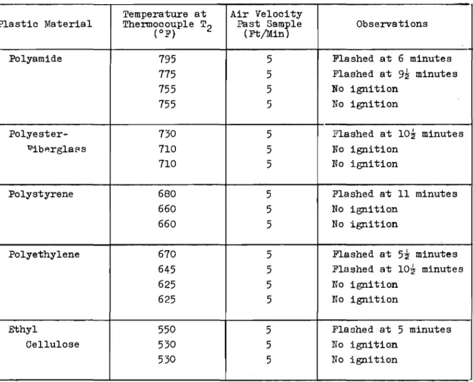
The flash- and self-ignition temperatures obtained at
I
the three specified air flows during these rising temperature runs are listed in Table 10 Except for the ーッャケ・ウエ・イセヲゥ「・イァャ。ウウ and the polystyrene samples, for which no self-ignition point could be obtained, optimum flow for self-ignition temperature determinations was similar to that found in flash-ignition tests, and corresponded in every case to a linear air velocity past the sample of 5 feet per mtrnrte ,
In the cases of the polyamide and ethyl cellulose, however, there was at least one alternate セーエゥュオュ flow at which the flash-ignition point could have been determined, but since the
9
-value of 5 feet per minute fitted every case, it was adopted as the optimum flow even when an alternative existedo
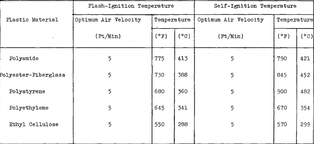
Tables II and III summarize results obtained during constant temperature
runs
aimed at determining minimum flash- and self-ignition temperatures respectivelyo These minimum ignition temperatures have been listed separately in TableIV
for each ofthe five plastic materials testedo
50
COMMENTSResults from four of the participating laboratories are $till unavailable and it would therefore be presumptuous to express at this time an opinion on the merits of the Setchkin method in the determination of the ignition properties of plastic materials. Complete results from three laboratories indicate, however, that good correlation between the participating agencies can be
expected o
As a result of this laboratorygs participation in the tests, it has been possible to appreciate some of the merits of the proposed test method, eogo elaborate but well detailed pro-cedure, and simple design and low cost of testing equipment •
.
There are, however, slight modifications either in procedure or equipment that would probably improve further the over-all appli-cability of the method0 These are discussed below o5010
Temperature scale: Fahrenheit versus CelsiusIn the suggested procedure supplied to the participating laboratories, all temperatures are expressed in Celsius degrees only0 At this stage in the development of the testing procedure
this may be オョゥセーッイエ。ョエL but since some laboratories are ・アオゥセー・、
degrees, it is suggested that both temperature values (Fahrenheit and Celsius) be givenG This would be in accord with what seems to be a general policy adopted by the ASTM in the publication of its standardsG
5020 Optimum flow-rate determinations
According to the ウオァァ・セエ・、 procedure, the optimum flow rate is determined by conducting series of tests at a rate of
heating of 11000F per hour using successive air flows corresponding to linear air velocities past the sample of 5, 15, and 20 feet per minute. Although, as mentioned previously, these determinations had to be performed in this laboratory at a rate of temperature rise of 600°F, it should be remarked that, for all the materials tested under these conditions, the optimum flow rate was found
to be the lowest of the three specified, that ゥウセエィ。エ corresponding to a linear velocity of 5 feet per minute. No lower flow rates were experimented upon, but it is questionable whether lower
ignition temperature values would have been obtained had lower flows been used.
One item in the procedure that is not understood in this laboratory is the reason for omitting the linear velocity of 10 feet per minute.
5.3G Modification of equipment
For the constant temperature runs, the furnace has to be preheated to a predetermined constant temperature before the sample can be introduced. It has been found in this laboratory that during the preheating period a spare cover for the furnace helped greatly in manipulating the sample, especially its
11
-The procedure adopted in the DBR laboratory was as follows: during the preheating period, the spare cover was set on the
furnace and the cover used normally during the tests was held
オーイゥァセエ on a laboratory support 」ャッセ・ to the furnace. When the furnace temperature reached steady 」ッョ、ゥエゥッョウセ the sample container with the required quantity of plastic material was set in position
on its holder, the pilot flame lit where specififed, and the normal cover was rapidly substituted for the spare cover. The changeover operation could be done in a matter of a few seconds. Blank runs had shown that the substitution of a cold cover for the hot one did not increase the temperature drop normally experienced
during the introduction of the sample following the specified procedure.
REFERENCES
I. Setchkin, N.P. A method and apparatus for determining the
ignition characteristics of plastics. Journal of Research of the National Bureau of Standards, Vol. 43, 1949, p.591.
(Research Paper RP2052)
Rセ Method of test for defining non-combustibility of bUilding materials. American Society. for Testing Materials, 'Standard E 136-58To
30
Setchkin Self-Ignition Apparatus for Solids, Model CS88 Custom Scientific Instruments, Inc. j Kearny, N.J.40 Brown, C.R. The determination of the ignition temperatures of solid materials0 Fuel, Vol. 14, 1935, po14, 56, 80,
Wlastic Material Polyamide Polyester-セゥ「・イァャ。ウS Polystyrene Polyethylene Ethyl Cellulose Rate of Temperature illse ( °C/Hour) 600 600 600 600 600 600 600 600 600 600 600 600 600 600 600 l\ir Velocity Past Sample Crt/Min) 5 15 20 5 15 20 5 15 20 5 15 20 5 15 20 Flash-Ignition Temperature ( OF) 830 835 830 740 790 820 700 760 800 680 710 720 600 600 600 Self-Ignition Temperature ( OF) 830 940 940 No ignition No ignition 670 675 720 580 615 610
TABLE II
DETERMINATION OF FLASH-IGNITION TEMPERATURE
.
Temperature at Air Velocity
Plastic Material Thermocouple T2 Past Sample Observations
(OF) (Ft!Min)
Polyamide 195 5 Flashed at 6 minutes
115 5 Flashed at Yセ minutes
155 5 No ignition
155 5 No ignition
Polyester- 130 5 Flashed at ャoセ minutes
li'ibp.rgla8s 110 5 No ignition
110 5 No ignition
Polystyrene 680 5 Flashed at 11 minutes
660 5 No ignition
660 5 No ignition
Polyethylene 610 5 Flashed at Uセ minutes
645 5 Flashed at lO;t minutes
625 5 No ignition
625 5 No ignition
Ethyl 550 5 Flashed at 5 minutes
Cellulose 530 5 No ignition
Temperature at Air Velocity Observations Plastic Material Thermocouple T2 Past Sample
( OF) (Ft/Min)
Polyamide 790 5 Flashed at 8 minutes
770 5 No ignition
770 5 No ignition
Polyester- 045 5 lnashed at ::; minutes
Fiberglass 830 5 No ignition
830 5 No ignition
Polystyrene 900 5 Flashed at 1 minute
885 5 Volatilized
880 5 Volatilized
Polyethylene 670 5 Flashed at 6 minutes
655 5 No ignition
655 5 No ignition
Ethyl 570 5 Flashed at 5 minutes
Cellulose 550 5 No ignition
TABLE IV
MINIMUM flashセ AND selfMigniセion TEMPERATURES
Flash-Ignition Temperature Self-Ignition Temperature
Plastic Material Optimum Air Velocity Temperature Optimum Air Velocity Temperature
-(Ft/Min) (OF) (OC) (Ft/Min) (OF) (OC)
Polyamide
5
775
413
5
790
421
Polyester-Fiberglass
5
730
388
5
845
452
Polystyrene
5
680
360
5
900
482
Polyethylene
5
645
341
5
670
354
AIR FLOW TANGENTIAL TO CYLINDER TUBE
PILOT FLAME
BRASS CLAMP FOR GAS BURNER,
SAMPLE HOLDER AND
THERMOCOUPLE T, セ]BB]LM[Zセセセャュセセイ]⦅gas セセセz]セセセゥヲヲャmイセセセセセ[ᄃセセMMMMMMMasbestos GASKET セ :::::;:::;:v..TO AIR FLOWMETER ASBESTOS WOOL SAMPLE セ CONTAINER C1l HEATING COILS PROTECTED WITH ALUNDUM CEMENT (50 TURNS #16 NICKE L- CHROME WIRE) ONE OF THREE SPACER BLOCKS SUPPORTING INNER TUBE セ w 0:: 0 REMOVABLE ::!: INSPECTION 0:: 0
.
\0 3" 4" 10" ASBESTOS CEMENT COVER TERMINALSFIGURE 2 SETCHKIN SELF- IGNITION APPARATUS