Publisher’s version / Version de l'éditeur:
ASHRAE Journal, 2, 9, pp. 49-54, 1960-09-01
READ THESE TERMS AND CONDITIONS CAREFULLY BEFORE USING THIS WEBSITE. https://nrc-publications.canada.ca/eng/copyright
Vous avez des questions? Nous pouvons vous aider. Pour communiquer directement avec un auteur, consultez la première page de la revue dans laquelle son article a été publié afin de trouver ses coordonnées. Si vous n’arrivez pas à les repérer, communiquez avec nous à [email protected].
Questions? Contact the NRC Publications Archive team at
[email protected]. If you wish to email the authors directly, please see the first page of the publication for their contact information.
NRC Publications Archive
Archives des publications du CNRC
This publication could be one of several versions: author’s original, accepted manuscript or the publisher’s version. / La version de cette publication peut être l’une des suivantes : la version prépublication de l’auteur, la version acceptée du manuscrit ou la version de l’éditeur.
Access and use of this website and the material on it are subject to the Terms and Conditions set forth at
Draft performance of chimneys
Brown, W. G.; Wachmann, C.
https://publications-cnrc.canada.ca/fra/droits
L’accès à ce site Web et l’utilisation de son contenu sont assujettis aux conditions présentées dans le site LISEZ CES CONDITIONS ATTENTIVEMENT AVANT D’UTILISER CE SITE WEB.
NRC Publications Record / Notice d'Archives des publications de CNRC:
https://nrc-publications.canada.ca/eng/view/object/?id=94091768-7647-40e0-bf0a-6b18b74a94ed https://publications-cnrc.canada.ca/fra/voir/objet/?id=94091768-7647-40e0-bf0a-6b18b74a94ed
her
TH1
1V21r 2
no.
108c. 2
NATIONAL RESEARCH COUNCIL
- .
c ~ i
;
E
CANADA
5NOV 1960
1
DIVISION OF BUILDING RESEARCH
J
I
DRAFT PERFORMANCE OF CHIMNEYS
W.
6. Brown and
C.
Wachmann
PRICE 10 CENTS
Reprinted from the ASHRAE JOURNAL, Vol. 2,
No. 9, September 1960, pp. 49-54. Olficial
publication of the American Society of Heating,
Refrigerating and Air
-
Conditioning Engineers
RESEARCH PAPER NO. 108
OF THE
DIVISION OF BUILDING RESEARCH
OTTAWA
SEPTEMBER 1960
I
This publication is being distributed by the Division of Building Research of the National Research Council as a contribution towards better building in Canada. It should not be reproduced in whole or in part, without permission of the original publisher. The Division would be glad to be of assistance in obtaining such permission.
Publications of the Division of Building Research may be obtained by mailing the appropriate remittance: ( a Bank, Express, or Post Office Money Order or a cheque made payable at par in Ottawa, to the Receiver General of Canada, credit National Research Council) to the National Research Council, Ottawa. Stamps are not acceptable.
A coupon system has been introduced to make payments for publications relatively simple. Coupons are available in denominations of 5, 25, and 50
cents, and may be obtained by making a remittance as indicated above. These coupons may be used for the purchase of all National Research Council publications including specifications of the Canadian Government Speci- fications Board.
Draft performance
&A a 4 s4 kY" ZW. G. BROWN
WACHMANN
Recently published information on the draft performance of domestic ~ h i m n e y s , ' ~ ~ ~ although obtained for specific chimney shapes and sizes, has been useful in estimating performance for many actual con- ditions. Occasionally, however, in- formation is required which does not fall within the limits covered by these test records, for example in chimneys of unusual shape or size, and some suitable design pro- cedure is required.
In this connection, many solely mathematical approaches to the prediction of chimney performance have been made4 and are still being made5 without the benefit of ex- perimental comparison. More re- cently, Schmitt and Engdah13 have shown indirectlv that these mathe-
The effect of wind on chimney draft performance has not been studied in detail in actual chimney installations although Schmitt and Engdahl have made a laboratory study which showed wind could either improve or retard the ability of a chimney to exhaust its gases, depending on the direction of the wind. Model studies by Wannen- burg and Van Straaten6 to deter- mine the pressures over the walls and roofs of buildings indicated that the performance of a chimney in wind would probably depend on the shape and orientation of the building.
Calm conditions, under which the available performance records have been obtained, are not fre- quent. In Ottawa, Canada, for ex-
of the year.7 Although these wind effects are likely to be of considera- ble importance in some chimney installations, there is every indica- tion that they can be treated sepa- rately from the performance under conditions of no wind."8 Hence be- fore attempting to analyze these effects the steady no-wind perfonn- ance should be established as com- pletely as possible.
-
1; a kevious papers the gen-
eral theory of steady-state chimney performance was developed and ap- peared to compare well with the experimental records for one of the fourteen chimneys tested by Achen- bach and Cole.2 Friction losses for the chimney were determined by isothermal tests on a model, the as- sumption being that the losses were essentially the same for non-iso- thermal flow of the chimney gases. To study further the usefulness of the design method indicated by the theory, tests were suggested to de- termine the friction losses for other shapes and sizes of chimneys. This work has now been extended and results of both model friction-loss tests and draft tests on a masonry chimney are reported in this paper. matical calculations compare quite h p l e , calm periods occur on a
poorly with experiment. They pro- yearly basis only 1 to 2 per cent TrnORY
posed an empirical design method of the time and wind speeds of 6 As reported pre~iously,~ the draft
for masonry chimneys 10 to 25 f t to 8 mph occur during 30 per cent available in a chimney could be de-
in height and with cross-sectional
areas of 35 to 55 sq in., which has
been included in ~ ~ ~ A S H A E Guide.
This design method has been criti- cized for accuracy, because some other records1 disagreed consider- ably for chimney heights slightly greater than 25 ft.
-
W. G. Brown is a ~ R e s w c h Officer, and C.
Wachmann a former 'Research Officer. Div of
Building Research, 'National Research Council,
Canada. This paper, here slightly condensed, is a contribution of the Div of Building Re- search of the National Research Council of Canada and is published with the approval of the Director of the Qivision: it was pre- sented a t the ASHRAE Semiannual Meeting in Dallas, Texas, February 1-4. 1960.
Draft, efficiency, and friction loss records obtained with masonry chimneys of three different heights were com- pared with previous records and with calculations based on model tests. The non-isothermal friction losses were found to be far greater than isothermal losses due to natural convection effects. The effect of low wind speeds over the chimney top was also found to be considerable. Similar wind effects were found
in
model tests and this indicates that wind effects for chimneys can be treated separately from steady-state performance and studied using models.temined with reasonable accuracy Cp = specific heat of the chimney Equation (5) equates the heat loss-
from the equationsv:
w
= gases mass flow rate of the chim- by the ehimney gases to the heatD pm
v m a
ney gases flow across @e chimney walls.= Y(1- K ---- -1 K = the chimney friction factor
A pm 2gH (for isothermal flow a t least, A P T gH
(1) dependent only on the Reyn- V, d TEST PROCEDURE EQUIPMENT AND and
F H Tn
where:
D = chimney draft (ambient air pressure minus pressure a t chimney inlet)
A p~ = difference in density between ambient air and chimney gas a t the chimney inlet
g = acceleration due to gravity H = chimney height above chim-
ney inlet
A p, = mean difference in density between ambient air and chimney g a s within the chim- ney
p , = mean chimney gas density
V, =mean chimney gas velocity T, = temp corresponding to the
mean chimney gas density (absolute)
To = ambient air temp (absolute) TI = chimney inlet temp (abso-
lute)
TR = room air temp (absolute) f o r inside chimneys (equal to To for outside chimneys)
F = a constant depending only on the geometry of the chimney
R = thermal resistance of the chimney walls
-
* These equations are given in slightly differ- ent form from that used previously.
olds number
-
where d isJ'm
a characteristic chimney size parameter, usually diam, and
v,,
.
is the kinematic viscos- ity).Equation,(l) is the basic equa- tion for chimney draft relating
D
chimney eEciency, ----, to fric-
*PT gH Vm2
tion pressure loss, Kpm-- and to
2
heat exchange through the chimney
walls as manifest in the term Y.
Equation (3), giving the tempera-
ture Tm corresponding to the mean
chimney gas density is derived by eliminating the chimney exit tem-
perature T2 from the two following
equations: T m = TI - F(T1- T ? ) and ( 4 ) H W C,(TI
-
T2) =-
(Tm-
Tn) R (5)Equations (4) and (5) presume that
the temperature drop occurring throughout the chimney is approxi: mately linear and that the tempeia- ture corresponding to the mean density of the chimney gases is the same as the mean temperature.
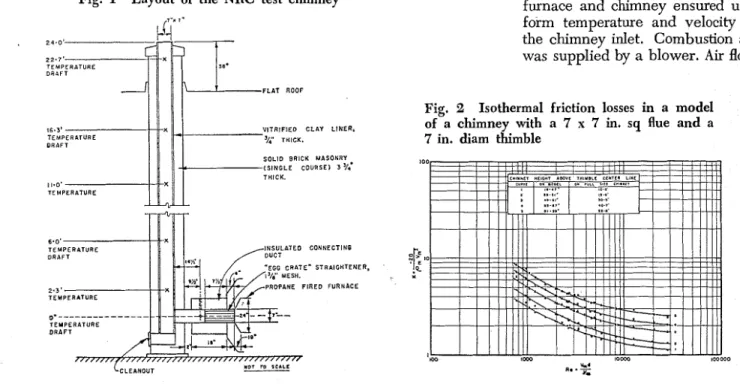
Fig. 1 Layout of the NRC test chimney
NRC masonry chimney
-
The testchimney (to be referred to as the
NRC chimney), (Fig. l ) , was con-
structed of standard clay brick with a vitrified clay liner firmly grouted into place. Flue dimensions were 7 x 7 in. The chimney thimble, a 7-in. inside diam pteel tube, entered the chimney at Jight angles 3.3 i t
above the floor.
.
Overall chimneyheight above the thimble center- line was 24.0 ft, of which 38 in. extended above the top of the con- taining building. Draft probes were installed in the connecting duct 1.2
ft from the inside face of the chim-
ney liner and at flue center-line 6.0, 16.3, and 22.7 ft above the thimble center-line. During tests differen- tial drafts between the thimble and various points along the vertical chimney were measured by con- necting the draft probes to a micro- manometer. Bare chromel-alumel thermocouples were installed. at connecting duct center-line, at the position of the draft probe and a t flue center-line a t heights above thimble of 2.3, 6.0, 11.0, 16.3 and 22.7 ft. In addition, an aspirating thermocouple was used to check thermocouple readings.
Flue pas for the tests was SUD-
plied by aFropane furnace. An e&-
crate type air straightener fitted in
the connecting duct between the furnace and chimnev ensured uni- form temperature and velocity at the chimney inlet. Combustion air was supplied by a blower. Air flow
D R I F T
FLAT ROOF
Fig. 2 Isothermal friction losses in a model
16.3' V ~ T R ~ F I E O C L A Y LINER. of a chimney with a 7 x 7 in. sq flue and a TEHPERLTURE
DRAFT 3g THICK. 7 in. diam thimble
4
SOLID BRICK MASONRY ( S I N G L E COURSE1 3 )/r. THICK. 11.0' TEMPERATURE INSULATE0 CONNECTIN6 EGG C R A T E " STRAIGHTENI PROPANE F I R E D FURNACE TEMPERATURE.
6.0' '",""C",
' 0 100 100 300 400 500 600 100 l L U C OA(i FLOW I N POUNDS PER HOUR
G A S FLOW IN POUNDS PER HOUR
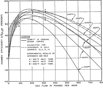
Fig. 3 Comparison of ASHAE design curves (Schmitt and Engdahl) with data of Achenbach and Cole and calculated performance
to the furnace was measured with calibrated orifices and propane gas flow was measured with a wet-test meter.
Models - Several models of conven-
tional chimney shapes, including that of the NRC chimney, were constructed of round and rectangu- lar tubing about 1/5 to 1/7 scale. Friction-loss tests on these models were conducted using the method previously o ~ t l i n e d . ~
Scope of tests -The NRC masonry chimney was tested at flue gas flow rates of 25, 50, 75 and 100 cfm, (standard air, 70 F and 29.92 in Hg), and at chimney inlet temperatures
of 350 F and 750 F. All tests were
made in summer and early fall, so room temperature Tn was essen- tially the same as the outside air
tem~erature Tn
.
showed the manner in which
K
varied with Reynolds number for -2D
isothermal flow. (Both K =
----
pmVmZ Vmd
and Re =
--
were computed onV
the basis of the mean chimney thimble velocity and thimble diam.) Results obtained with the other models were similar although values differed depending on the geome- try. Results were also similar to those observed previously8 for mod- els with round chimneys and thim- bles of the same size.
Before considering the test re- sults for the NRC masonry chimney, previous test records shall be com- pared with calculated performance based on the theory and using the model results for the friction factor
T r
I
-
The model chimneys were test- ed at room temperature at various flow rates corresponding to the range of Reynolds numbers ob- served in full-size chimneys,
RESULTS AND OBSERVATIONS
Isothermal friction tests with mod-
els
-
Results of tests to determinethe friction factor on a model of the NRC masonry chimney (Fig. 2)
A.
Results of tests by Achenbach and Cole2 on four masonry chim- neys of cinder concrete 15% ft high and having geometry similar to that of the NRC chimney have been
D
plotted in Fig. 3 as
----
againstAPT gH
flow rate as suggested by Schmitt and EngdahL3 The recommended design curves of the latter authors are included for comparison. The
Fig. 4 Efficiencies of the
NRC test chimney. (Inlet temp 350 F)
Fig. 5 Efficiencies of the NRC test chimney. (Inlet temp 750'F)
experimental results agrec moder- ately well with the design curves in the range of flow rates tested, but there is an indication that at high rates (above 300 Ib/hr) agree- ment will be increasingly poor. This is especially noticeable at a gas temperature of 200 F. Similarly, the shape of the design curves appears to be considerably differ- ent from that of the experimental curves.
With the assumption that fric- tion losses in non-isothermal flow
remain essentially the same as in
isothermal flow it is now possible to use Equations (1) to (3) to cal- culate the performance of the brick chimneys. The factors F and R (both assumed constant) in Equa- tion (3) are difficult to calculate accurately, however, hence the ac- tual experimental temperature data for the four chimneys were used to determine average values.
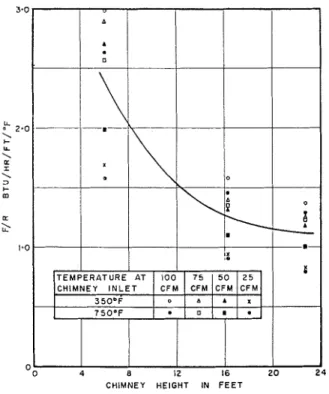
Using Equation (3) and the mean flue gas temperature as given by Achenbach and Cole, the mean
value of F/R was found to be 1.2
Btu/hr/F/ft. (It was necessary to
assume TR = 70 F for these calcu-
lations since indoor air temperature was not given.) Using this average value of F/R and Equation (3), the
CHIMNEY HEIGHT IN F E E T
Fig. 6 FIR values for the NRC test chimney
temperatures at several flow rates were calculated and substituted
into Equations (1) and (2) along
wit11 the friction factor K deter-
mined from the model tests. The calculated e5ciency-flow- rate curves are superimposed on the experimental results (Fig. 3). The theoretical curves agree well with the experimental results but do not agree with the design curves, especially at low chimney inlet temperatures and high gas flow rates.
Remaining records for all four- teen chimneys tested by Aclienbach and Cole were analyzed as above using the model results for the dif- ferent chimney shapes. This study showed similar agreement between calculated and observed perform- ance. All these chimneys were
tested in the range 85 to 320 lb/hr
and showed e5ciencies in the same range as those of Fig. 3. Each type of chimney construction, however,
had its own specsc e5ciency
-
flow-rate relationship.
Draft performance of the NRC
chimney
-
Although the aboveanalysis appeared to confirm that
Equations (1) to (3) could be used
for chimney design purposes, some doubt remained as to the validity of the assumption that friction pressure-loss would be the same
HEIGHT ABOVE THlM8LE g IN F E E T
Fig. 7 Inverse of temperature at flue center-
line in the NRC test chimney
under isothermal and nonisother- ma1 conditions. The NRC masonry chimney was operated therefore to obtain further records of draft for different chimney heights. This in- formation can be compared with that given by Achenbach and Cole. As pointed out, the draft in the NRC chimney was measured dif- ferentially between a point in the connecting duct near the thimble and the chimney. This method of measurement was necessary be-
cause even notably low winds over the chimney top were found to con- tribute significantly to the draft when measured in the usual way (i.e. between the ambient air and a point in the thimble). This effect was versed by simple wind tests on a model, which also offer sup- port for the previously proposed method8 of using models to study wind effects. (Results of these
studies are given in Tables I and
TABLE I
EFFECT OF WlND OVER TOP OF NRC MASONRY CHIMNEY
Draft measured differentially between W i n d Ratio of d r a f t induced
thimble and a point I ft below Draft measured between thimble Draft induced W i n d velocity t o wind velocity
chimney t o p and outside air by wind velocity pressure pressure
0.012 t o 0.014 in. water
urements the net draft for no-wind conditions for different heights of chimney could be obtained without the necessity of building separate chimneys or having large openings in them at various heights (cf. I).* Test results for the NRC chirn- ney, with flue gas inlet tempera- tures of 350 and 750 F are given in
Figs. 4 and 5. Chimney efficiencies
for the 16.3-ft chimney are in fair agreement with th$ results of Achenbach and Cole. Results for all three heights at 350 F inlet tem- perature agreed poorly with the Schmitt and Engdahl design curves at the higher flow rates, and in general agreed only approximately at lower flow rates. The relative performance of the three heights was not regular: at low flow rates the 6.0-ft chimney had the greatest efficiencies, while at high flow rates the efficiencies for the 16.343 and 22.7-ft chimneys were greatest. To check the effect on performance caused by chimney inlet conditions,
0.025 t o 0.027 0.041 .
0.039 in. water in. water 9 mph in. water 0.6 t o 0.7
Fan position 24 in. horizontally from chimney t o p 8 in. horizontally from chimney t o p TABLE II EFFECT OF A HORIZONTAL WlND OVER MODEL CHIMNEY TOP
Draft induced W i n d velocity
by wind pressure
0.0 16 t o 0.024 0.028 t o 0.03 1
in. water in. water
0.03 1 t o 0.05 1 0.059 t o 0.079
in. water in. water
the air straightener was removed from the chimney thimble and tests repeated. Results were only slight- ly affected by this procedure. The values of F/R (Fig. 6) did not differ greatly from those of Achenbach and Cole, although values were somewhat greater for the 6.0-ft chimney than for the other two heights.
Since the differential method of obtaining draft measurements on the NRC chimney allowed more accurate results than previously ob- tained, an attempt was made to de- termine the actual friction losses
-
Some authors (1, 4) claim a "stack effect" occurring in non-isothermal flow.
exists above the physical height o f a chimney The measured value of a, obtained
which causes an increase in draft in the absence , ...
of wind. However. there ap-s to be no from an average of the inverse of experimental or theoretical evidence available
to support this contention. temperature at the chimney center-
Fig. 9 Comparison of non-isothermal and isothermal friction losses for the NRC test chimney. (Chimney inlet temp 750 F)
REYNOLDS NUMBER RI
.=
J'm Ratio of draft induced to velocity pressure 0.5 t o 0.8line (Fig. 7) was inserted into Equa-
tions (1) and (2), which were then
solved for the non-isothermal fric-
tion factor K,. Results (Figs. 8 and
9), although somewhat inconsistent,
especially for the 6.0-ft chimney, show values much greater than for isothermal flow (model results given for comparison) except at high flow rates where convergence becomes apparent. Furthermore, it can be
seen that the magnitude of K, also
depends on the chimney gas tem- perature.
The large friction factors ob- tained in non-isothermal flow call be clarified in part by a new the- ory for pressure loss and heat ex- change in vertical tubes,g which in- dicates that the Grashof number, gd3paT
---- , influences the friction pres-
u2
sure loss as well as the heat flow. At low flow rates in the chimney tests the Grashof number was large in comparison with the Reynolds number and greatly influenced the friction losses. At these low flow rates the turbulence due to insta- bility was much greater than that occurring in the normal isothermal turbulent range and the friction loss was consequently increased.
Although calculated chimney performance based on the iso- thermal friction losses appeared to correlate fairly well in previous it now becomes clear that this method is only applicable to high flow rates and to a quite limit- ed range of chimney sizes. In the
size range of domestic chimneys large errors in estimating the fric-
tion factor Kn do not greatly affect
the calculated chimney e5ciericy: For extrapolation of results for other sizes of chimneys the method suggested previously8 should be modified to incorporate the non-
isothermal factor Kn instead of K
for isothermal conditions. In the present work the measurements were not su5cient to determine the
manner in which Kn depends on the
Grashof number, ' hence caution
should be exercised in extrapolat- ing figures. It is hoped that this matter can be further clarified at a later date. Since natural convection as evidenced by the Grashof num- ber is present at low flows, mixing would always occur and chimney efficiency would not tend to zero as suggested by the Schmitt and Eng- dahl design curves.
CONCLUSIONS
Since friction losses were found to be much higher for' non-isothermal flow than for isothermal flow, care should be exercised in extrapolating available results for other shapes
and sizes of chimneys. In particu- lar, old methods of design which sim ly assuFe friction losses in the verfcil flue to be the sarhe as for smooth pipes in isothermal flow are likely to be con~iderably in error. Before a complete design method for chimneys of all sizes can be proposed, a more thorough study of natural convection effects will be needed.
Tests on the NRC chimney
were in essential agreement with other experimental work covering a narrow range of domestic chim- ney sizes. The design curves of Schmitt and Engdahl, however, ap- pear to be considerably in error at high and at exceedingly low flow rates.
Incidental tests to study wind effects over the chimney top were verified by model results. This work in turn indicated that wind can be treated separately..firom steady-state performance andjcan be studied using models. . i ' '
R. G. Evans i n d J. E. Berndt as-
sisted with construction and the
recording of results and the authors record their thanks for this assist- ance. The authors also acknowled~e
guidance; given to this project
gy
A. G. Wilson, head of the Building.
Services section in which the wori was carried out.
REFERENCES
1. Observed Performance of Some Experimen- tal Chimneys, R. S. Dill. P. R. Achenbach, and J. T. Duck. (ASHAE Transactions, Vol.
48, 1042, p. 351-368).
2. Performance of Fourteen Masonrv Chim- neys under Steady State conditions P. R. Achenbach and 'S. D. Cole. (ASHAE Trans- actions, Vol. 66. ,1949, p. 129-1154).
3. Performance of Residential Chimneys. L. B. Schmitt ,and R B EnPdahl. (ASHAE Trans-
actions. Vol. 5$ 194< ),P 241-262): -
4. Dra.ft and Capacity of Chimneys. J. G. Mingle. (Combustion Publishing Corn., 1926).
5. Using Mathematics in Heating and Ventila- tion. E Woodcock. lHeatine and Ventilatinn ~ n s i n e e r & Journal of &r Conditionins. Vol. 30, N w . 359 and 360, 'May and June,
1957, p. 547-553 and p. 606-612).
6. Wind Tunnel Tests on Scale Model Build- ings as a Means for Studying Ventilation and Allied Problems. J. J. Wannenburg and J. F. Van Stmzten. (Journal of the Institution of Heating and Ventilating Engineers. Vol. 24, March 1967, p. 477-492).
7. Private communication from D. W. Boyd, Division of Building Research, National R e smrch Council, Ottawa, Canada.
8. Fundamentals of Chimney Performance, W.
G. Brown and W. G. Colborne. (Canadian Journal of Technology, Vol. 34, No. 5, Sep- tember 1956. p. 354-365).
9. Der Einfluss des Auftriebs auf Warmeii- bergang und Druckgefalle bei erzwungener Stromung in senkrechten Rohren, W. G. Brown and P. Gr-ann. (Forsohung auf dem Gebiete des Ingenieurwesens, Vol. 25, No. 3.
1959. p. 63-78).
A list of all publications of the Division of Building Research is available and may be obtained from the Publications
, Section, Division of Building Research,