READ THESE TERMS AND CONDITIONS CAREFULLY BEFORE USING THIS WEBSITE. https://nrc-publications.canada.ca/eng/copyright
Vous avez des questions? Nous pouvons vous aider. Pour communiquer directement avec un auteur, consultez la première page de la revue dans laquelle son article a été publié afin de trouver ses coordonnées. Si vous n’arrivez pas à les repérer, communiquez avec nous à [email protected].
Questions? Contact the NRC Publications Archive team at
[email protected]. If you wish to email the authors directly, please see the first page of the publication for their contact information.
NRC Publications Archive
Archives des publications du CNRC
This publication could be one of several versions: author’s original, accepted manuscript or the publisher’s version. / La version de cette publication peut être l’une des suivantes : la version prépublication de l’auteur, la version acceptée du manuscrit ou la version de l’éditeur.
Access and use of this website and the material on it are subject to the Terms and Conditions set forth at
Evaluation of factory-sealed double glazed window units
Wilson, A. G.; Solvason, K. R.; Nowak, E. S.
https://publications-cnrc.canada.ca/fra/droits
L’accès à ce site Web et l’utilisation de son contenu sont assujettis aux conditions présentées dans le site LISEZ CES CONDITIONS ATTENTIVEMENT AVANT D’UTILISER CE SITE WEB.
NRC Publications Record / Notice d'Archives des publications de CNRC:
https://nrc-publications.canada.ca/eng/view/object/?id=88c5dfa4-34a3-4fcb-a62a-6027fbbcd5e8 https://publications-cnrc.canada.ca/fra/voir/objet/?id=88c5dfa4-34a3-4fcb-a62a-6027fbbcd5e8NATIONAL
RESEARCH
COUNCIL
CANADA
DIVISION O F BUILDING RESEARCH
EVALUATION O F
FACTORY
-
SEALED DOUBLE
-
GLAZED WINDOW UNITS
BY
A. G. WILSON. K. R. SOLVASON AND E. S. NOWAK
R E P R I N T E D FROM
AMERICAN SOCIETY F O R TESTING MATERIALS SYMPOSIUM O N TESTING WINDOW ASSEMBLIES SPECIAL TECHNICAL PUBLICATION NO. 251.
1959. P. 3
-
1 6R E S E A R C H P A P E R N O . 8 5 O F THE
DIVISION O F BUILDING RESEARCH
' . Z . , , , , \ ' L , ;, . .. ,: . 7 L 7 7. - - . -. . b (2 ,,
;.
<:! ! , --
NOVEMBER 1959 PRICE 2 5 C E N T S N R C 5 2 7 0This p u b l i c a t i o n i s b e i n g d i s t r i b u t e d by t h e Division of Building Research of t h e National Research Council a s a contribuLion towards b e t t e r b u i l d i n g i n Canada. It should not be reproduced i n whole o r i n p a r t , without permission of t h e o r i - g i n a l publisher. The D i v i s i o n would be glad t o be of a s s i s t a n c e i n o b t a i n i n g such permission.
Authorized Reprint from the Copyrighted
Symposium on Testing Window Assemblies
Special Tcclrtcical P~cblicalion iVo. 251
Published b y the
American Society f o r Testing Materials
1958
EVALUATION O F FACTORY-SEALED DOUBLE-GLAZED WINDOW UNITS
General performance requirements for sealed double-glazed windows and the need for performance tests are discussed. The possibility of condensation of moisture and clouding or scumming on the inside glass surfaces is empha- sized. The results of some exploratory studies on the degree of sealing achieved in a number of units and on condensation on the interior surface are given. These results are based on measurements of the dew point of the air between the panes and on surface temperature measurements taken with various tem- perature differences across the windows. Factors involved in determining the adequacy of the sealing of the space between the panes are considered and lines of study suggested. General requirements of a test procedure for determining the degree of sealing achieved and the relative life of seals are discussed and accelerated aging apparatus proposed for this purpose is de-
I
scribed.
T h e number of mailufacturers in Canada of factory-sealed double-glazed units intended for use in buildings was very limited until quite recently. Units being marketed had been developed over the years from a background of field and laboratory experience. I n the past year or two, however, several new manufac- turers of sealed windows have entered the Canadian market, due in part to the availability of new compounds for seal- ing purposes. There has apparently been a ready market for these sealed units in housing construction, largely created by the advertising of established firms.
No performance standards or test pro-
'
Building Services Section, Division ofBuilding Research, National Research Council
of Canada, Ottawa, Ont.
cedures directly applicable to evaluating these units have been published. The Division
6f
Building Research of the National Research Council of Canada was therefore asked by Central Mortgage and Housing Corp. (CMHC) t o assist in developing a basis for determining the acceptability of various factory-sealed units for use in houses built under the terms of the National Housing Act of Canada. Submissions to C M H C by manufacturers for acceptance were often accompanied with the results of ad /LOGtests designed to show that the units could withstand extremes in exposure without failing. There was no basis, how- ever, on which to determine the signifi- cance of the tests or results.
As a beginning, the Division obtained N.R.C. 5270
specimens
ei
a
number of types of sealed viihdows and carried out some simple ex- ploratory tests. The second step was to arrange for discussions with technical representatives of two of the major pro- ducers in the United States who have much technical experience in this field. This was done through affiliated Cana- dian companies and the fullest coopera- tion was received from all concerned.With this background, a tentative basis of evaluation has been arrived a t and apparatus has been designed to provide the necessary conditions of ex- posure. I t is hoped that this work will contribute to the ultimate preparation of a product specification.
The sealing of the space between the panes of double windows is sometimes incorrectly assumed by the layman to be associated with some advantage in reducing heat transmission. I n actual fact, the sealing of the space against the entry of air, water vapor, and dust is necessary because the space between the panes is inaccessible for cleaning. Indeed, the need to clean only two surfaces is one of the major advantages claimed for such windows. Another advantage claimed for sealed windows is that there is no condensation between the Danes to obscure vision. The space between the panes is usually stated to be dry.
This implies that the dew point within the space is low and that the units are sufficiently well sealed so that the dew point does not rise during service to the point where significant condensation be- tween the panes can occur.
There is another, perhaps more im- portant, reason for the maintenance of a low dew point condition between the panes. According to technical representa- tives of glass producers, alkalies are pres- ent in most common glasses. When the
surface of glass is wetted and dried, this alkali, principally sodium salt, is brought slowly to the surface, forming a cloudy film. This is sometimes referred to as scumming and is a common form of glass soiling. When glass is accessible for cleaning, this film is readily washed away. Such soiling of the inaccessible glass surfaces of sealed units may, how- ever, be regarded as highly undesirable, if not as an indication of failure of the units.
I t would appear, then, that the dew point condition of the space between the panes and the degree to which a seal is obtained and maintained, are important aspects of the performance of factory- sealed window units. The degree of seal- ing necessary will depend on the serious- ness of condensation and soiling. This is related to the basis on which the units are sold or purchased. Objections to the appearance of condensation between the panes may be partly psychological, be- cause purchasers normally assume t h a t it will not occur. Small patches of con- densation that occur only during the coldest weather might otherwise n i t b e regarded as serious. Substantial conden- sation that occurs even in relatively mild weather, however, not only obscures vision through the window but is a n indication of potential soiling of the glass through leaching of the alkalies. This may have the effect of lowering the value of the building in which this occurs and is therefore the concern of any lending institution involved as well as the owner. Breakage of sealed double-glazed win- dows is of special importance because of the relatively high- replacement cost. Failures induced by stresses resulting from temperature differences are there- fore of
articular
concern in cold cli- mates. Such failures when due to im- proper installation are outside the scope of a product specification. Weaknesses in the design of the units that may lead toglass breakage should, however, be ex- posed by test methods.
Another factor in connection with any window arrangement is condensation on inside surfaces. Double windows are used almost universally in Canadian houses, and increasingly in commercial buildings, in order to reduce winter heat losses and inside surface condensation as well as summer heat gains. Even double win- dows have a higher heat loss factor than other elements of buildings in most in- stances, and the relative humidity that can be carried is, therefore, limited by window surface condensation. The ad- vantage of double windows over single windows in permitting higher inside rela- tive humidities without excessive con- densation is partly lost if a high conduc- tivity sash or frame is used. Ideally, the construction around the periphery of the window should not result in inside sur- face temperatures lower than those that would otherwise occur on the glass sur- face.
Exploratory tests were carried out on seven different types of factory-sealed double-glazed units to obtain informa- tion on the dew points of the space be- tween the panes, the adequacy of the seals, and the inside surface temperatures as related to the edge construction. Three specimens of each type were installed in panels between a warm and a cold room. All units were approximately 20 by 40 in.
Inside surface temperatures were measured with the cold room held suc- cessively a t temperatures of 38, 20, 0, -20 and -40 F, with the warm room a t 72 F, the relative humidity in the latter being lowered to avoid surface condensation. I n the test with the cold room at -40 F, an air stream heated to 170 F was directed over the inner panes in an attempt to simulate the thermal
shock that might occur in windows in- stalled over radiators or warm air out- lets. The cold room was next cycled daily between 20 F and -20 F for two weeks, with the warm room at 70 F and 30 per cent relative humidity. Observations of inside surface condensation were made over a two-week period with the cold room held successively at temperatures from 20 F to -40 F and with different levels of relative humidity in the warm room. Finally, the cold room was main- tained for one week at 20 F with the warm room a t 70 F and 40 per cent relative humidity. Units were examined periodically for condensation between the panes throughout the tests. Before and after installation between warm and cold rooms, the units were stored in the cold room a t -40 F and examined for condensation between the panes. Meas- urements of the over-all thickness at the center of the units were made in the cold room for comparison with thickness measurements a t room temperature.
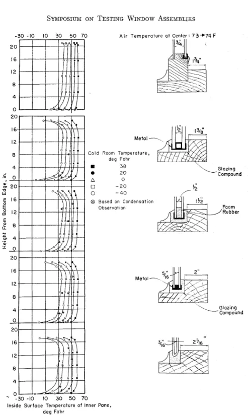
The results of inside surface tem- perature measurements on one specimen of each of four different units are shown in Fig. 1 together with the method of mounting and details of each of the units. The surface temperatures were taken along the vertical center line of the speci- mens with copper-constantan thermo- couples (Brown & Sharpe gage 30) in coniunction with an electronic indicat- ing potentiometer. During the measure- ments, the temperature of the cold room was controlled within f 0.25 F with an air temperature gradient over the height of the glazing units not greater than 0.25 F. Air movement over the outer pane was downwards a t about 7 mph.
eati in^
of the warm room was by an electric baseboard convector on the wall opposite and approximately 7 ft from that con-A i r T e r n ~ e r a t u r e o t C e n t e r = 7 3 + 7 4 F
Cold Room Ternperoture, deg Fohr I 38 \ a 2 0
'.
A 0 0-
2 0 0 - 4 0 @I Bosed on Condensation Observot Ion " - 3 0 -10 10 3 0 5 0 7 0 Inside Surface Temperature o f Inner Pone,d e g Fohr Glozing Compound Foam /Rubber \Glozing Compound
taining the glazing units. The air tem- perature variation a t any point in the warm room did not exceed f 1 F and the air temperature gradient over the height of the units did not exceed 0.5 F. Shown a t the top of Fig. 1 for comparison purposes are surface temperature gra- dients obtained for a simple wood-sash window having: dimensions similar to
-
those of the factory-sealed units.For the measurements of inside sur- face temperature, each thermocouple junction and approximately 1 in. of bared wire were fastened to the window in a horizontal position with black plastic tape extending about in. beyond the thermocouple tip. More extensive meas- urements on the wood window obtained subsequently indicated that the tem- peratures so measured might be higher than the actual surface temperatures by as much as 1 F a t a cold room tempera- ture of 38 F and 3.5 F a t a cold room temperature of -40 F.
Surface temperatures along the verti- cal center line of the factory-sealed units were also obtained from observations of the extent of surface condensation and the known room dew point temperatures during the cold room tests. These values, also shown in Fig. 1, are in fair agree- ment with the - vertical tem~erature gradient curves. The observations of condensation were, however, somewhat crude for purposes of establishing surface temperatures.
Inside surface condensation always formed initially as a band of constant height across the bottom of the unit. As
-
the dew point temperature was increased, the condensation would next occur along the two vertical edges and then across the top edge, framing the unit. The ex- tent of condensation in this pattern would increase with increasing dew point until the entire unit was covered. These observations are in agreement with the vertical temperature patterns shown inFig. 1. I t will be noted that there are large surface temperature gradients near the top and bottom of the factory-sealed units with smaller gradients in the central region. The wood window has similar temperature gradients in the central region, but the gradients in the vicinity of the top and bottom edges are not so pronounced.
The increase in surface temperatures with height that occurs in the central region with all units can be attributed mainly to vertical temperature gradients in the air spaces resulting from convec- tion. These were measured in the wood window and found to be substantial. For example, a t a cold room temperature of 0 F, the difference in temperature be- tween the top and bottom of the air space was 28 F. A decrease in this air space temperature gradient with decreas- ing air space thickness would be ex- pected. There are, however, definite in- side surface temperature gradients in the central region, even with an air space width of
&
in., suggesting significant vertical air temperature gradients. Sur- face temperatures a t the center of the windows are consistent in general with the thickness of the air spaces and in reasonable agreement with calculated values. The small difference in center surface temperatures at the higher cold room temperatures between units having &-in. and $-in. air spaces is noteworthy. The sharp temperature gradients a t the edges of the factory-sealed units re- sult in condensation near the edges a t much lower relative humidities than will produce condensation in the central re- gion of the units. These gradients can be attributed mainly to edge heat loss effects, although the degree to which the units are recessed in the wall construc- tion may also be a factor. The degree of recessing was comparable in all the units shown in Fig. 1. The extent to which the edges of the factory-sealed units areburied in glazing compound will also affect the edge surface temperatures. The installation of the units tested was in this respect in accordance with the distributors' instructions. The edge sur- face temperatures are generally lowest with the units having edges of highest conductance. However, the difference between the factory-sealed units in this respect is again small, particularly a t the higher cold room temperatures. Edge sur- face temperatures with the wooden unit are substantially higher at all cold room temperatures.
iting condensation between the panes showed very little deflection, indicating equalization of the air space pressures with outside as a result of leaks.
I n considering the results of the cold room tests in relation to evaluating the adequacy of the seals, i t was concluded that the laboratory conditions were not sufficiently severe or prolonged to repre- sent the degree of aging that would be provided by actual conditions during the required service life. I t was clear that
BRASS FUNNEL
AIR SPACE
I/a"
L U C I T ERESERVOIR
THIN SECTION
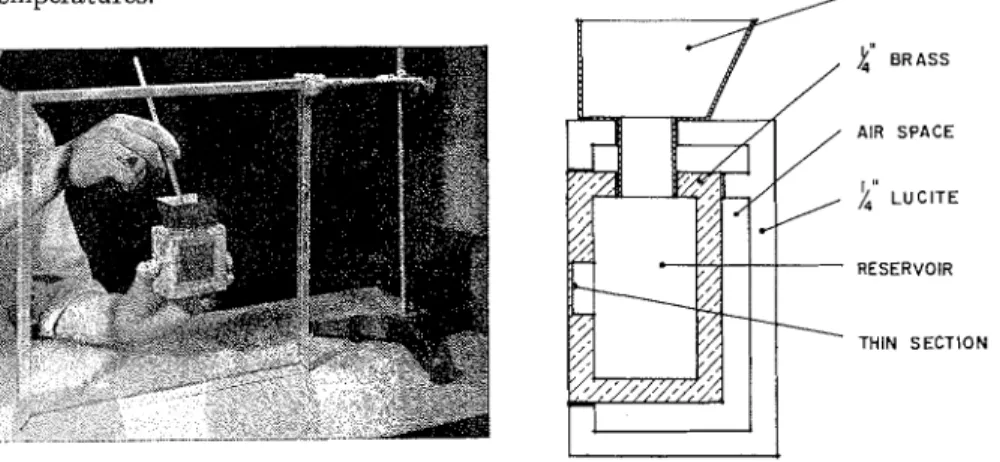
FIG. 2 . - A p p a r a t u s for Window D e w p o i n t M e a s u r e m e n t . No frost was observed between the
panes of four of the units at any stage in the cold room tests, although small patches of frost were observed in the other three units at all cold room tem- peratures. During the cycling test, a considerable amount of ice formed on the inside surface of the outer pane of one specimen, but this was the only case in which any accumulation of water be- tween the panes was observed.
The several units showed different amounts of deflection a t the center dur- ing storage in the cold room. Generally the amount of deflection increased with increasing air space thickness. A few of the specimens among those units exhib-
the degree of accelerated aging that could be provided by the cold room apparatus was limited, since it was not possible to produce rapid cycling of temperatures. I t was also concluded that the observa- tions of frost or water accumulation be- tween the panes did not provide a suffi- cient basis for determining the adequacy of the units and that some refinement in the method of determining the moisture condition within the space was necessary. I t was suspected that moisture accumula- tion between the panes of some of the specimens might have occurred but for the protection afforded by the glazing compound used for installation.
The specimens used in the cold room tests were stored a t room temDerature for approximately two years. The dew points in the air spaces were then meas- ured with the apparatus shown in Fig. 2. This apparatus and the technique used for measuring the dew point of the space between the panes was patterned after methods used by the two glass labora- tories visited by the authors in the United States. The flat ex~osed metal face is held firmly against one face of a double-glazed unit while dry ice is dromed into acetone contained in the
. .
reservoir to provide the desired tempera- ture as measured with a thermometer. The temperature of the acetone and dry ice is lowered in steps until condensation in the form of liquid water or frost ap- pears as a small circular patch on the air space side of the glass in contact with the metal face. Observations for conden- sation are made by removing the appara- tus following each change in temperature and quickly wiping the glass surface with acetone. Once condensation is ob- served, the dew point can be re-estab- lished more precisely by using smaller steps in temperature. I t was possible to reproduce dew point measurements within about5
F, the major limitation being the control of the acetone dry ice temperature.The temperature of the glass surface Jn which condensation forms is some- what higher than the temperature of the acetone as a result of the lateral heat flow along the glass and the temperature gradient through glass and metal. Thus the actual dew point of the space will be higher than that measured. The differ- ence between actual and measured values will increase with decreasing dew point temperatures. Where the method is being used for comparative purposes, for prod- uct control or development in a given
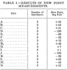
laboratory, reproducibility and not ac- curacy is important. If, however, the method is to be used in specifications, it must be standardized and some further investigation of it would be warranted. Results of the dew point measurements are given in Table I. Specimens A to G were those used in the cold room studies;
B1
to N were new units obtained shortly before the dew point measurements were made. The dew points for units A to C are approximately equal to that of the storage room. I t would appear that the leaks in the seals are such that the spacesTABLE I.-RESULTS OF D E W POINT MEASURElMENTS.
Unit Number of Specimens Dew Point, deg Failr
assume the same average vapor pressure as that of the surrounding atmosphere.
I t is clear that the degree to which a seal is obtained and maintained in sealed double-glazed units is a major considera- tion in their evaluation. The degree of sealing required is associated in the first instance with the desirability of main- taining a low dew point condition, or a t least avoiding objectionable condensa- tion, between the panes.
small cracks and openings in the seal by diffusion as a result of vapor pressure differences, or as a component of air that moves under total pressure differences caused by temperature changes or baro- metric pressure changes. As long as the vapor pressure or dew point inside the space is below the ambient value, there will be a net gain in water vapor to the space due to these flow mechanisms if there are any openings.
Different degrees of sealing of double windows can be envisaged in terms of the dew point temperatures maintained in the space between panes. Several es-
definitely established by technologists in the glass industry. Presumably, water in the liquid phase is required and, there- fore, dew points above 32 F are to be avoided if scumming is regarded as a problem. I t was suggested by one source that dew points above 50 F led to serious scumming. With sealing as in (2) above, there should be no problem so long as the inaximum permissible dew point is properly established.
If there are openings in the seal, or if these develop, it can be envisaged that ultimately the space between the panes will come into equilibrium with the en-
TABLE 11.-AVERAGE DEW POINT TEMPEIZATURE, D E G FAllR
City
/
Jan./
~ e b . 1 ~ a r . 1 Apr.1
M a y / ~ u n e / July/
~ u g . 1 Sept./
Oct.INOV.
I
~ e c . ( A n n u a lamples are listed below :
1. During required service life, the dew point within the space does not change signihcantly from the original value,
2. During required service life, the dew point within the space does not rise above some established maximum value, or
3. During required service life the dew point within the space comes into equilib- rium with the environment.
. . . Vancouver, B.C.. . . . Edmonton, Alta.. . . . Saskatoon, Sask.. . . . Winnipeg, M a n . . Windsor, Ont.. . . . . . . Toronto (Malton), Ont..
. . . Montreal (Dorval), P.Q.. . . . Moncton, N.B.. . . . Halifax, N.S..
With sealing as in (1) above, there should be no problem with either scum- ming or condensation between the panes if the initial dew point is low enough. I t is not known by the authors if the con- ditions leading to, or the time required for, appreciable scumming have been
36 7 3 2 20 16 8 12 18
vironment. If the openings are extremely small, this might not occur within the recluired life of the unit. With somewhat greater leakage, the dew point in the space might come into long-term equilib- rium with the environment during this " period, equivalent to the mean of aver- age annual ambient conditions.
I n such a case, if the cracks or open- ings connect the space to the outside, the dew point in the space rill level out a t the meail annual outside dew point. The monthly and yearly average outside dew point temperatures for some Cana- dian cities are given in Table II.Z
I t can be seen that in no instance does Based on data contained in "Climatic Sum- maries of Sclccted Meteorological Stations in the Dominion of Canada," VoI. 1, AleteorologicaI Division of tlie Canadian Department of Trans- port, Ottawa, Ont.
the annual average dew point exceed 50 F. On this basis, units in long-term equi- librium with the outside environment should not exhibit objectionable scum- ming. However, if the cracks or openings were such that the air space followed monthly fluctuations in outside dew point, the dew point of the space could exceed 50 F during two to four months of the year. Regardless of the degree of sealing provided, there would appear to be no problem with condensation be- tween panes seriously obscuring vision when leaks in the seal are to the outside, since there is no accumulation of water, unless rain can enter.
The dew point inside many nonaircon- ditioned buildings in the summer can be assumed approximately equal to the out- side dew point. During the winter the dew point in occupied buildings is higher than outside, being limited in general by the inside surface temperatures of the windows. On the other hand, the dew point inside the air space of a double window can be no higher than the tem- perature of the outside pane regardless of the amount of moisture present. Thus, if the leaks in the seal connect the air space to the inside there will be an ac- cumulation of water as liquid or solid in the space between the panes during the winter.
The amount of water that can accumu- late under given environmental condi- tions will depend on the degree of seal leakage. I t might amount to little more than small patches of water or frost or it might be sufficient to obscure vision through a substantial part of the window under some weather conditions.
If moisture accumulates between the panes during the winter, the relative humidity in the space will be essentially 100 per cent during the summer until this moisture is released. During this period the dew point in the space will correspond to the air space temperature
and the time during which the dew point can exceed 50 F will be extended in pro- portion to the time required to release the wintertime moisture accumulation. The question arises as to whether mois- ture that accumulates between the panes during the winter is entirely released during more favorable conditions or is partly carried over from year to year with a gradual annual accumulation. A
simple calculation for the Ottawa-Mon- treal region indicates that accumulation from year to year in this or milder cli- mates is improbable, even under condi- tions of high wintertime inside relative humidity. In more severe climates, the results of the calculation depend on the choice of wintertime inside relative hu- midities.
In the calculation, based on monthly time increments, it was assumed that the number of cycles of pressure difference between the air space and room air are equally distributed throughout the year and that the inflow or outflow of vapor from the space between the panes can be taken as proportional to the difference in humidity ratio or vapor pressure between the space and inside the building. Inside vapor pressure was taken as that corre- sponding to saturation at the tempera- ture of the inner pane during the winter and equal to outside vapor pressure dur- ing the summer, while the air space vapor pressure was taken as that corresponding to saturation a t the temperature of the outer pane during the winter and corre- sponding to saturation a t outside air temperature during the summer.
On the basis of the foregoing, it ap- pears that, if the dew point of the space between the panes of sealed units follows short-term fluctuations in ambient dew point, objectionable condensation be- tween the panes is likely to occur. Some direct observations of the degree of con- densation that occurs under service con- ditions with specimens providing differ-
ent degrees of sealing would be useful. If the space comes into long-term equi- librium, equivalent to the annual aver- age of ambient conditions, the units are suspect from the point of view of even- tual scumming. It is important to estab- lish what psychrometric conditions be- tween the panes of sealed units can be tolerated without soiling of the glass by leaching of alkalies. Presumably this will depend on the amount of alkali present in the glass. Advice from the glass indus- try on this point is required. Finally, test methods are required to determine what degree of sealing is provided by speci- mens of factory-sealed units and the de- gree to which specimens will maintain a seal during service life.
The foregoing considerations, together with discussions with experts involved in the development of factory-sealed units, have led to a number of general conclu-
-
sions regarding physical tests for deter- mining the adequacy of the seals of fac- torv-sealed units. - 2For purposes of determining the ac- ceptability of the psychrometric condi- tions between the panes a t any time and as an index of the ability of a unit to maintain its seal under simulated service conditions, direct dew point measure- ments are essential. These can be made with apparatus similar to that shown in Fig. 2.
The time required for pressure between panes to equalize with ambient pressure can be an extremely useful index in quickly identifying those units that have very poor seals. To determine these times, the units are exposed to lowered temperatures or pressures and the deflec- tion a t the center measured. The use of a vacuum chamber would be advanta-
geous since a wider range of pressure differences can be provided and effects of barometric pressure changes during a test can be avoided.
I n determining the durability of the seals, the conditions of exposure must accelerate failure of specimens to simu- late service over several years. The test should be capable of causing the eventual failure of any practical unit. The condi- tions should create the type of stress on the seal that will occur in service. For units used in building construction, these stresses are principally the result of tem- perature cycles. Therefore, cycling tem- perature conditions are necessary to create realistic stresses and, at the same time, to induce water vapor transfer by creating total pressure differences be- tween the space and outside. Average ambient vapor pressures during testing should be sufficiently high so that leaks in the seals can be detected by a rise in dew point of the air space. Provision of temperature gradients across the units during artificial weathering is desirable since this may cause stresses not other- wise provided and is conducive to mois- ture accumulation between the panes.
Since there will be differences in per- formance between specimens of a given unit and since some failures in all prac- tical units can be expected, testing of a large number of specimens is desirable. The specimen size should be as small as practical so as to minimize specimen costs and the size of the apparatus re- quired. Since specimen size may be a factor in the durability of the seals, sizes should be similar for comparative testing of different units. The effect of specimen size on the durability of the seals in a given unit should perhaps be investi- gated. Since air space thickness may have an effect on the rate of dew point rise, testing of each thickness of a given seal design would seem necessary.
APPARATUS AND PROCEDURES FOR 20 in. This size was chosen as a minimum EVALUATING FACTORY-SEALED based on advice received from experts in UNITS the industry. The testing apparatus was designed to accommodate 24 units of this With this background, procedures and size. I t can, however, be used for any test apparatus are being developed along size of unit up to j f t 6 in. square.
the following lines for evaluation of fac-
F~~~
heating coils have been provided. tory-sealed units marketed in Canada: These consist of electric tubular heaters 1. Determination of the relative tight- placed inside finned tubing to increase ness of the seals and the relative mois- the heater surface area. cooling is ture content the space between panes achieved by a direct expansion Freon 12 as received, system, consisting of a 12-row finned 2. Determination of the of tube evaporator and a water-cooled con- the seals as indicated by the ability of densing unit. The heating and cooling specimens withstand coils are spaced uniformly between the weathering without excessive rise in dew test windows to provide a uniform ex- point of the 'pace between panes, and posure for all specimens. To aid further 3. Correlation of laboratory test re- in uniformity of exposure and also to suits with observations under increase air film conductances, two fans weather conditions. are used to provide air circulation. The fans draw air from the lower duct, dis- As an index of initial seal tightness, charging it into the top ductvia
the twospecimens as received will be placed in a side ducts and down the space between vacuum test ~ l ~ a m b e r with dial gages to the test windows. The lower duct also measure glass deflection with vacuums serves to drain the spray water back to UP to 5 in. of mercury. The absellce of its tank situated on the floor. The space initial glass deflection will indicate a between frames was kept to a minimum large leak in the seal; an initial deflection to reduce the volume flow rate required that subsides slowly, a smaller leak; and to provide a given air velocity.
a sustained deflection a substantial de- ~h~ test samples will be mounted in a gree of tightness. simple frame of $-in. plywood as shown
The dew point apparatus already de- in Fig. 3. This type of mounting was scribed, although not indicatil~g the exact selected rather than that used in the field dew point, will be used to determine the in order to espose all of the sample edges. relative moisture content of the air be- ~t is believed that glazing compoun~ tween panes as received and during ex- may in some cases defective seals. posure to accelerated weathering. I t is anticipated that only units t h a t For accelerated seal durability tests, a have showll no leakage in the vacuum weather simulating device for windows test need be subjected to the weathering is being developed. The apparatus, ~hov'n test. The weathering cycle can be varied in Fig. 3, was designed to expose one but the one proposed is as follows: side of the factory-sealed units to cycling 1. Cooling until the inside glass sur- temperatures and a water spray, with face temperature reaches -20 to -30 F, the other side exposed to controlled room 2. Heating until the inside glass sur- conditions. The test specimens are to be face temperature reaches 120 to 130 F, mounted on either side of the heating 3. Cooling until the inside glass sur- coils, cooling coils, and sprays to form a face temperature drops to about 110 F, 12-in. air space. I t is anticipated that 4. Spray inside surface with water a t test specimens will generally be 14 by 70 to 75 F, and
5.
A short rest period to allow water to drain, then repeat (1) to (4).The whole cycle is expected to take 3 to 4 hr permitting some 6 to 8 cycles per day. Longer cycles are, of course, pos- sible. Dew point temperatures of the space between the panes will be meas- ured regularly during exposure, and the rise in dew point during a given number of cycles will be the criterion of perform- ance of the glazing units. The number of cycles that a unit should withstand with- out excessive rise in dew point will re- quire investigation. I t has been suggested that, as a minimum, units should with- stand 300 cycles of a somewhat similar exposure without the dew point exceed- ing 30 F. For some purposes, classifica- tion of units based on the number of cycles that can be withstood without ex- cessive dew point rise might be con- sidered.
Consideration is being given to long- term exposure of units with both sides exposed to the weather with periodic measurements of the dew point in the space. Records of dew point rise might provide a useful comparison with the re- sults of measurements with the weather simulating apparatus. The degree to which the dew points are sensitive to outside dew point conditions would pro- vide an index of tightness that could be compared withlaboratory results. Finally, observations of the degree of leaching of alkalies on the unexposed faces as related to measured dew point conditions ivould provide some informati011 on maximum permissible dew points.
Consideration is also being given to installation of units with defective seals, either as received or as a result of the weather simulating treatment, in outdoor test huts with controlled interior condi- tions. Observations of such units would indicate the degree to which condensa- tion formed between the panes and the
extent of scumming at known dew points of the space between panes.
There is an increasing need for stand- ard test procedures and specifications for factory-sealed double-glazed units be- cause of their increasing use in buildings and the increasing number of manufac- turers. Apart from thermal performance, the provision and maintenance of a low dew point between the panes appears to be the maior reauirement. Low dew points are desirable in order to prevent condensation between the panes and soiling of the glass by leaching of alkalies. Standard test procedures are required to measure the dew point conditions in the space of factory-sealed units, to measure the relative degree of sealing provided, and to determine the extent to which a unit can maintain a tight seal under serv- ice conditions. Test apparatus and meth- ods being developed for this purpose, based largely on procedures now in use by the industry, have been described. Information is required on the relative degree of sealing required to avoid ob- iectionable condensation between the panes and on the psychrometric condi- tions that lead to soiling of glass by leaching of alkalies. Some information on
the
relations hi^
between the effect ofartificial weathering and actual weather- ing on dew point rise in factory-sealed double units is also needed.
The authors are greatly indebted to 0. D. Engelhart and M. N. Zeolla, Glass Research Laboratories, Pittsburgh Plate Glass Co., and F. Rodman, J. D . Gmyn, and H. F. Goeckel, Technical Service, Libbey-Owens-Ford Glass Co. for the opportunities provided to inspect labora- tory facilities and for much helpful infor- mation and advice. The authors are also grateful for useful discussions with R.
W. McKinley, Pittsburgh Plate Glass Industries Ltd., and W. D. Anderson, Co., J. A. Ferguson, Canadian Pittsburgh Pilkington (Canada) Ltd.