Publisher’s version / Version de l'éditeur:
Vous avez des questions? Nous pouvons vous aider. Pour communiquer directement avec un auteur, consultez la première page de la revue dans laquelle son article a été publié afin de trouver ses coordonnées. Si vous n’arrivez pas à les repérer, communiquez avec nous à [email protected].
Questions? Contact the NRC Publications Archive team at
[email protected]. If you wish to email the authors directly, please see the first page of the publication for their contact information.
https://publications-cnrc.canada.ca/fra/droits
L’accès à ce site Web et l’utilisation de son contenu sont assujettis aux conditions présentées dans le site LISEZ CES CONDITIONS ATTENTIVEMENT AVANT D’UTILISER CE SITE WEB.
Housing Note (National Research Council of Canada. Division of Building
Research); Volume 12
READ THESE TERMS AND CONDITIONS CAREFULLY BEFORE USING THIS WEBSITE.
https://nrc-publications.canada.ca/eng/copyright
NRC Publications Archive Record / Notice des Archives des publications du CNRC :
https://nrc-publications.canada.ca/eng/view/object/?id=f82808b5-824d-4cde-ab81-25e7b9646345
https://publications-cnrc.canada.ca/fra/voir/objet/?id=f82808b5-824d-4cde-ab81-25e7b9646345
NRC Publications Archive
Archives des publications du CNRC
This publication could be one of several versions: author’s original, accepted manuscript or the publisher’s version. / La version de cette publication peut être l’une des suivantes : la version prépublication de l’auteur, la version acceptée du manuscrit ou la version de l’éditeur.
Access and use of this website and the material on it are subject to the Terms and Conditions set forth at
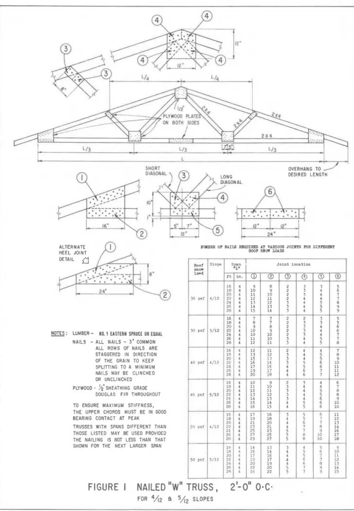
New Nailed "W" Roof Truss Designs Offer Small Builders Advantages
Ser
NA7110
~ 2 1 h 8
no.
12
c .
2
NATIONAL RESEARCH COUNCIL
CANADA
DIVISION OF BUILDING RESEARCH
HOUSING NOTE NO. 12
M E MAILED "W" ROOF TRUSS DIESAGMS
OFFER SMALL BUILDERS ADYAMTAMS
by
A. T.
HANSEN
REPRINTED FROM
CANADIAN BUILDER, VOL. XIII, NO. 8
AUGUST 1963, P. 44
OTTAWA, AUGUST 1963
Mew unaiilled
'
'
roof truss designs
offer srna!! builders advantages
For several years the Division of Building Research, National Research Council, and the Forest Products
P Re'search Branch of the Department
r
of Forestry have carried out an ex-'
tensive truss testing program to de- These standard nailed truss designs velop standard roof truss designs for have a number of important advant- use in house construction.
ages, especially for smaller volume builders. Among them:
1-The designs have been proof test- ed either at Forest Products Lab- oratories or at the Division of Building Research in Ottawa. They conform to the requirements of the Housing Standards. This means that a builder can use the trusses without the expense of further proof tests or engineering if they are used in an area where the National Building Code (1960) is enforced.
2-These designs are cconomical in that a typical truss, spaced 2 ft. O.C. with 2 x 4 members, requires only slightly more than half the lumber required for typical joist and rafter roof framing using 2 x
6 members 16 in. O.C. The amount of labor will naturally vary with the amount of nailing required. For a typical truss with 26-ft. span and 5/12 slope, to be used in a 50-psf snow load area, observa- tions made during fabrication at
DRR indicated that about 53 min- utes are required for one man to cut, assemble and nail all the members for the design shown in Figure 1.
3-Nailed truss designs are particular- ly suitable for small builders who wish to make their own trusses in that no special pneumatic or hy- draulic equipment is necessary to assemble the trusses. The trusses can be built either in a shop or on the site using the subfloor as an assembly area.
The first part of this work led to the publication of a number of nailed truss designs intended for use in areas with roof snow loads not exceeding 50 Ib/sq ft (at 24-in. spacing). The designs were accepted by Central Mortgage and Housing Corporation for use in houses built under the Na- tional Housing Act. These designs for 24- to 28-ft spans and 4/ 12 and 5 / 12 roof slopes, were reproduced by Central Mortgage and Housing Cor- poration in Builders' Bulletin No. 94 2nd with slight revisions in Builders' Bulletin No. 109.
Subseqr~ent to the publication of these designs, further testing was car- ried out to develop designs for 30- and 40-lb snow load areas. In addition, designs were developed to include 3/ 12 slope trusses as well as 4/ 12 and
Method for assei
A simple method of providing a jig for accurate assembly of the truss members is to first draw the full size truss with chalk lines on the assembly bench or subfloor and mark the po- sitions of the gusset plates. Wood cleats, usually about 2 in. thick and a foot or so long are then nailed on either side of where the truss mem- bers will lie, in sufficient numbers to hold the members in the correct rela- tive positions while the truss is being assembled.
5/12 slopes, and the range of spa extended to include trusses of 16 32 f t in length (in 2-ft incremenl
This last series of truss designs w also accepted by Central Mortgage a Housing Corporation for use in how built under the National Housing A and were recently reproduced CMHC in ~ u i l d e r s ' ~ u l i e t i n No. 1~ This bulletin is available free charge and may be obtained eitk from CMHC or the Division of Bui, ing Research.
Figures 1 and 2 show some of t designs available in this bulletin. 1
of these designs meet the perfor] ance requirements in Housing Star ards, Canada, 1963 which forms St plement No. 5 to the National Bui ing Code. These requirements st; that the trusses must be able to w i ~ stand the ceiling load plus twice t design snow load for a 24-hour I riod and must not deflect more th 1/360 of the span when loaded w the ceiling load plus the design snc load for a period of one hour.
T
I
ensures that the trusses in general w be at least as strong as well-built jo and rafter roofs.nbling trusses
pieces which may be used for mar ing out the members for the remai ing trusses.
Degree of Precision Necessary The trusses are designed so tk precision cutting of most members not essential. In fact, most membt may be square cut. It is importa~ however, that the top chord membc be accurately cut where they meet the peak and that these members in good contact before the gusz plates are installed. This may be s
The pieces for the first truss should
complished by nailing the top me1 then be measured against the truss as bers together at the peak before t indicated by the chalk lines and ac-
OVERHANG TO DESIRED LENGTH
ALTERNATE B U ~ ~ E R OF BAIIS R B P ~ R E D AT VARIOUS JOI~ITS POR DIFFBREIIT HEEL JOINT ROOF SBOW LOADS
DETAIL
NOTES : LGMBER
-
NO. 1 EASTERN SPRUCE OR EDUAL-
NAILS
-
ALL NAILS-
3' COMMON ALL ROWS OF NAILS ARE STAGGERED IN DIRECTION OF THE GRAIN TO KEEP SPLITTING TO A MINIMUM NAILS MAY BE CLINCHED OR UNCLINCHED PLYWOOD -9;
SHEATHING GRADEDOUGLAS F I R THROUGHOUT TO ENSURE MAXIMUM STIFFNESS. THE UPPER CHORDS MUST BE IN GOOD BEARING CONTACT AT PEAK
TRUSSES WITH SPANS DIFFERENT THAN THOSE LISTED MAY BE USED PROVIDED THE NAILING IS NOT LESS THAN THAT SHOWN FOR THE NEXT LARGER SPAN
FIGURE I
NAILED
"w"
TRUSS,
2'0"
0.C.
.
3 O p s f
40 psi
ROO^ Slope span J o i n t l o c a t i o n anow "L" l o r d i t i n . @ @ @ @ @ @
I : : ~ ~
I a 5/12 4/12--
24 4 1 7 16 4 5 6 26 4 1 9 17 4 6 7 28 4 20 18 4 6 I 1 6 4 1 0 9 2 3 4 1 8 4 1 1 1 0 3 4 4 2 0 4 1 2 1 1 3 4 5 40 psf 5/12 22 4 1 3 12 3 4 5 2 4 4 1 4 1 3 3 4 6 26 4 15 14 4 5 6 28 4 16 1 5 4 5 6 1 5 4 1 7 16 3 5 6 1 8 4 1 9 1 8 4 5 7 20 4 21 20 4 6 I 50 p s i 4/12 22 4 23 21 4 7 8 24 4 25 23 5 I 9 26 4 21 25 5 8 10 2U 4 29 2 1 5 8 10 1 0 4 14 1 3 3 4 5 1 8 4 16 1 4 4 5 6 20 1 17 16 4 5 I 50 psf 5/12 22 4 1 9 1 7 d 6 7 24 4 20 1 9 4 6 8 26 4 22 I 9 7 9 22 11 11 12 6 I 8 8 9 10 10 1 1 1 2 1 3 14 16 1 7 1 8 9 1 0 1 1 12 1 3 14 15 4 1 6 4 1 2 I 1 0 2 4 4 1 0 1 0 2 6 4 1 1 1 0 2 0 4 1 2 1 1 1 0 4 1 3 1 2 9 11;:
4 8 1 2 3 3 5 2 0 4 9 8 2 3 4 6 2 2 3 3 2 3 3 3 3 4 4 4 4 4 3 5 6 1 0 4 4 5 5 4 5 5 6 7 I 8 I 8 9not tightly fitted. It is essential, how- New nailed "W"
roof
ever, that the size and number oftruss
designs nails used at each joint be not less than as shown on the drawings since (Continued from page 2)the nailing largely determines truss performance. The nails should also be staggered in the direction of the grain gusset plates are nailed in place. The
to limit the amount of splitting that fit at the other joints is not critical
since the stiffness or strength of the may Occur. The used in making trusses will be relatively unaffected if the trusses shown in Figures I and 2 the members at the other joints are do not have to be clinched.
for load
TABLE 1
Truss spacing Allowable roof snow load (Ib/sq.ft)
24 in. O.C.
. . .
30 psf trusses.
. .
40 psf trusses. .
.
50 psf trusses20 in. 0.c.
. . .
36 psf trusses.
. .
48 psf trusses. . .
60 psf trusses16 in. O.C.
.
.
. 45 psf trusses. . .
60 psf trusses.
.
.
75 psf trusses 12 in. O.C.. .
. 60 psf trusses.
.
.
80 psf trusses. . .
100 psf trussesThe snow loads shown in Figures 1 and 2, for the various designs are based on truss spacings of 2 ft. If this spacing is reduced the trusses may be used in snow load areas greater than those shown. Table I shows how the allowable snow load may be altered by changing the truss spacing.
A an illustration of how this Table may be used, suppose the trusses are to be used in a 60-psf snow load area. One could use a truss originally designed for 30-psf snow load and 24-in. spacing by reducing the spac- ing to 12 in.; or one could use a 40- psf truss at 16 in. o.c.; or a 50-psf
truss at 20 in. O.C.
In general, the most economical ar- rangement as far as framing costs are concerned will be to use the widest spacing possible (up to 24 in.). It may be desirable in some cases, however, to select an arrangement that will give
a lesser spacing. A 16-in. spacing may be found to be preferable to a 20-in. spacing, for,example, if plywood roof sheathing or gypsum board ceilings are to be used, or if one wishes to use 16-in. wide insulation batts.
All of these things should be con- sidered in selecting the most economi- cal arrangement for a particular snow load area.