HAL Id: hal-00559434
https://hal.archives-ouvertes.fr/hal-00559434
Submitted on 25 Jan 2011
HAL is a multi-disciplinary open access
archive for the deposit and dissemination of sci-entific research documents, whether they are pub-lished or not. The documents may come from teaching and research institutions in France or abroad, or from public or private research centers.
L’archive ouverte pluridisciplinaire HAL, est destinée au dépôt et à la diffusion de documents scientifiques de niveau recherche, publiés ou non, émanant des établissements d’enseignement et de recherche français ou étrangers, des laboratoires publics ou privés.
Experiments of a twenty cell PEFC operating under
fault conditions with diode by-pass circuit for
uninterrupted power delivery
A. de Bernardinis, Denis Candusso, Fabien Harel, Gérard Coquery, X.
Francois
To cite this version:
A. de Bernardinis, Denis Candusso, Fabien Harel, Gérard Coquery, X. Francois. Experiments of a twenty cell PEFC operating under fault conditions with diode by-pass circuit for uninter-rupted power delivery. Energy Conversion and Management, Elsevier, 2010, vol.51 (n.5), pp1044-54. �10.1016/j.enconman.2009.12.008�. �hal-00559434�
Experiments of a twenty cell PEFC operating under fault conditions with
diode by-pass circuit for uninterrupted power delivery
Alexandre De Bernardinis a,*, Denis Candusso a,c, Fabien Harel b,c,
Xavier François d, Gérard Coquery a
a
The French National Institute for Transport and Safety Research (INRETS), Laboratory of New Technologies (LTN), 25, allée des Marronniers, 78000 Versailles Satory, France.
b
The French National Institute for Transport and Safety Research (INRETS), Transport and Environment Laboratory (LTE), 25, avenue François Mitterrand, Case n° 24, 69675 Bron Cedex, France.
c
FC LAB Institute, rue Ernest Thierry Mieg, 90010 Belfort Cedex, France.
d
FCLAB / University of Technology Belfort Montbéliard (UTBM), rue Ernest Thierry Mieg, 90010 Belfort Cedex, France.
E-mail:
alexandre.de-bernardinis@inrets.fr
*
Corresponding author. Tel: +33 (0)1 30 84 39 75; Fax: +33 (0)1 30 84 40 01
denis.candusso@inrets.fr fabien.harel@inrets.fr xavier.francois@utbm.fr gerard.coquery@inrets.fr
Energy Conversion and Management, Vol51, n5, pp1044-1054 Ed. Elsevier
Abstract
The work presents the results of experiments related to the electrical and dynamical behaviour of a 500W, twenty cell Polymer Electrolyte Fuel Cell (PEFC) stack operated under fault condition and connected to an anti-parallel diode acting as a by-pass. The stack is placed in an experimental set-up that reproduces the electrical coupling in series of two fuel cells. The results allow the evaluation of the by-pass diode solution in the case of specific degraded working modes such as the break of the gas reactant feeding. The experiments presented in this article constitute an extrapolation and a complementary investigation of the preliminary results already achieved on a two cell PEFC stack and which had demonstrated the capability of the reverse diode to electrically isolate a fuel cell stack under fault. The proposed experiments focus on the dynamic behaviour of the stack under degraded working modes and point out the key-role of the fuel cell stack impedance in the triggering of the anti-parallel diode switching.
Keywords: Polymer Electrolyte Fuel Cell; Multi-stack Fuel Cell; Fault tolerance; Degraded working modes; By-pass diode
1. Introduction
Today for many energy conversion systems involving fuel cells (FCs) for stationary, transportation or even auxiliary power units (APU) applications, it becomes crucial and
unavoidable to ensure a continuation of operation in case of a fault. It is essential to develop some technical concepts which permit degraded working modes and come to a fault tolerant fuel cell (FC) generator. Strengthen reliability, high power availability and power delivery continuation are fundamental for a vehicle (to reach the next station in case of a public transport) but also for
stand-alone applications which need uninterrupted power delivery (hospitals, APU for emergency…) [1,2]. Moreover the isolation of a FC stack under fault is important in order to protect its internal components which are very sensitive to degraded working situations. In the case of a Polymer Electrolyte Fuel Cell (PEFC) technology, the Membrane Electrode Assembly (MEA) can be subjected to different failures: membrane break, internal gas leakage, cell flooding or drying, poisoning of the catalysts areas...Redundancy and continuation of power delivery can be achieved through a multi-stack FC association when one FC stack remains out-of-work after a faulty operation [3,4,5]. A single stack (or group of cells) can be affected by several degradations during its operation, particularly when the power varies and consequently the amount of gas reactant. Some inhomogeneous gas distributions and induced local sub-stoichiometries (starvation phenomena) may also occur more frequently in larger stacks fed by fast gas flow changes. In some cases involving fast load variations, the coupling of FCs with additional buffer energy storage elements (super-capacitors, power batteries) is also required [6,7]. A hybrid FC system is often considered for transportation applications in order to adapt the dynamical response of the FC generator to transient load phases and for energy saving during the braking phases of the vehicle [6-8].
As an example of possible operating problem, let us consider the case of cells suffering from fuel starvation, which means that the cells are not fed with sufficient amounts of reactive gases. Then, the cell voltages will drop down below a low threshold, which can be critical for the cell operation and performances and for their lifetime as well. In order to isolate and protect the stack one solution consists in monitoring the cell voltages and shutting down an affected stack if a critical low voltage is detected. Another complementary solution should consist in the use of reverse by-pass diodes electrically connected in anti-parallel to each FC stack or groups of cells. These diodes can isolate the defective cells (or even an entire stack) and authorize the
ensure the continuation of power delivery by hydrogen / oxygen FC stacks in a sub-marine [9]. Some diodes can also be employed in order to protect either each individual cell or a group of cells within a stack. With the diodes allowing the deviation of the stack current, the cells are prevented against the possible adverse effect of low or reverse voltages. In the patents [4,5,9,10], the authors describe some FC systems comprising a plurality of stack assemblies having their integrated diodes.
The solution of by-pass diodes used in case of a faulty stack has already been evaluated at the FC LAB laboratory in Belfort. Preliminary works have been conducted on a two cell PEFC stack [11,12]. This first study is now extrapolated to a twenty cell PEFC stack. Experiments and test analyses through modelling are proposed in this article.
The article is organised as follow: First the problematic of power delivery continuation for multi-stack FCs using by-pass diodes is reminded. Secondly, a modelling and simulation
approach permit to describe the behaviour of the FC stack under a specific degraded conditions. The switching capability of the anti-parallel diode and the key-role of the FC internal resistance in the triggering of the diode conduction are pointed out. Then, experimental tests have been performed and the various results analysed. The twenty cell PEFC under test with its anti-parallel diode is respectively connected in series to a constant and adjustable DC voltage source (0-20V) which emulates a second FC. As a second experiment, the PEFC is connected in series to a 12V lead-acid battery to represent a hybrid power source. Some specific degraded working modes will be imposed to the FC stack alike the sudden interruption of the gas reactant feeding to the FC. The aim is to observe and understand the behaviour of the PEFC stack under these degraded situations and to validate experimentally the role of the anti-parallel diode as a by-pass to the faulty stack. Current and power regulations are applied to the load during the tests. Let us remind that the work should be especially useful for electrical engineers and easily understandable by
them since the models, simulations and tests presented in the paper are electrical engineering oriented.
2. Isolation of a FC stack under fault using a diode by-pass
As already mentioned in the introduction, an association of hydrogen / oxygen PEFC modules equipped with anti-parallel diodes has already been used in the case of an air
independent propulsion system for submarine application [9]. In the Submarine Class 212 from German Navy, eight 30-50kW PEFC modules are connected in series. If one of the FC modules fails, it is switched off, while the others continue to operate. Depending on the series connection of the FC modules, a diode connected between the electrical plugs of each module is necessary to ensure the current flow while one or more FC module(s) are out of operation. This principle of FC by-pass could be implemented in vehicles like electric buses, light rail vehicles (trams) taking into account the possible degraded working modes of the stacks linked to the constraints of the transportation environment.
The US patent publication [5] presents a switching system and control method implemented with a multi-stack FC system. The switching system enables FC stacks to be connected in series for providing power to load while removing the particular disadvantages of a series circuit. In the case of a stack fault, the faulty stack may be bypassed, whereby the remaining stacks provide power to the power user at a reduced capacity. The stack under fault is continuously monitored and is reintroduced to the series circuit if the fault clears. If the fault reoccurs once again “a predetermined number of times” after the stack has been reintroduced, a “reduced capacity” mode is initiated. Additionally, in the event of a reduced or an increased current demand, FC stacks are selectively switched in and out of the series connection, for limiting the overall operation voltage range of the FC stack system.
For the power supply of a DC network for on-board applications a possible solution should consist in using a power generator composed of n PEFC stacks connected in series (Fig. 1). This solution leads to an increase of the global input voltage and thus the voltage constraints on the load power converter are reduced as well as the current amplitude constraints for a given transmitted power. The FC multi-stack power generator is connected to a DC-DC power converter, which adapts the input voltage to the DC-Link voltage of the on-board electrical network. A battery imposes the DC bus potential and is also used for transient load power phases. For simplification, each FC stack is represented in Fig. 1 as an ideal voltage source with a static resistance in series.
Fig. 1. Possible simplified scheme for multi stack FC association equipped with anti-parallel by-pass diodes used for on-board systems.
Such an approach dealing with reliable operation involving protection by-pass diodes is also employed in photovoltaic (PV) generation systems. Some groups of ten to twenty PV cells connected in series to produce a reasonably high output voltage have an anti-parallel diode to ensure power delivery continuation in case of fault (mainly for partial lighting deficiency, a
by-pass diode serves to decrease the effect of shadowing in the photovoltaic system while
minimizing the power drops under shady conditions). The concerned references are mentioned in [13-18].
3. Approach by simulation for a twenty cell PEFC stack
The simulation represents the electrical coupling of a twenty cell PEFC stack with its anti-parallel diode (Diode AP) with a DC voltage source in order to simulate a twin-stack FC coupling. A contactor placed in series with the FC remains closed during the simulation. It is mainly used as a cut-off circuit for the stack protection or even is used to force a sudden circuit opening. Figure 2 shows the electrical circuit topology which was considered respectively for the simulation and following experiments described in section 4.
FC +
-On/Off switch Contactor UFC FC +
-Contactor UFC 0-20V DC supply LEM1 current sensor
20 cell PEFC voltage Electronic
load Electronic load LEM2 current sensor Diode S2 Diode AP Diode AP On/Off switch Contactor Contactor of the LOAD
Fig. 2. Electrical circuit topology showing the PEFC, the Diode AP and all the devices used for simulation and experiments.
The simulations are performed for two situations: first without and then with two additional diodes connected in series (Diode S2) with the FC stack under test. The addition of diode S2 will have a positive impact over the “switching on” behaviour of the anti-parallel Diode AP. It forces the triggering of the Diode AP conduction by imposing a sufficient voltage drop to enable the Diode AP conduction. Such a solution is necessary when the tested FC stack has some voltage and series resistance values that are too low to polarise the anti-parallel diode and to let it by-pass the FC current. The electrical source connected in series with the investigated stack is a 20V constant voltage source and the load current is imposed using a constant current source element. The model adopted for the FC is basically composed of an electrical voltage source E [V] in
series with a pure resistance Rm [Ω], which represents the high frequency impedance of the FC
corresponding to the resistance of the membranes. Such an (E, Rm) simplified model is sufficient
to analyse the “switching on” behaviour of the anti-parallel diode. Since the value of the
membrane resistance is always lower than the total polarization resistance, the (E, Rm) model can
be considered as the “worst-case” for the triggering of the anti-parallel diode conduction. The
value of the global twenty cell stack resistance (Rm) is 36 [mΩ]. The simulations are done with
the E [V] voltage decreasing from 20V to 0V as a ramp in order to simulate a progressive break
in the reactive gas feeding. Simulations are based on MATLAB/Simulink® software [19].
The currents involved in the circuit are linked by Eq. (1) and the FC voltage is given by Eq. (2):
DiodeAP FC Load I I I (1) FC m FC E R I U (2)
The Diode AP technology is a Fast Recovery Epitaxial Diode (FRED). The conduction threshold
of the Diode AP is VF = 2.2V (high voltage threshold for FRED diodes given at 25°C compared
to other conventional diodes technologies).
3.1. Diode AP switching condition without the addition of Diode S2 in series with the FC
If the internal resistance of the contactor placed in series with the FC stack is neglected, the
following relation Eq. (3) between the Diode AP voltage (VD_AK) and the FC voltage (VFC) is
obtained: FC m FC AK D U E R I V _ (3)
When E equals zero or reaches values close to zero (during the starvation phase in particular), the
FC behaves like a pure resistance (Rm) and the current in the FC stack is dependent both on the
resistance Rm and on the conducting threshold of the Diode AP (VF [V] diode forward voltage).
The current IFClim through the stack is limited by Eq. (4):
m F lim
FC V R
I (4)
Then, the following relations corresponding to two different states can be considered:
ILoad ≤ IFClim: Diode AP is blocked; IFC = I Load and IDiode AP= 0
ILoad > IFClim: Diode AP is conducting; IFC= IFClim and IDiode AP= ILoad - IFClim
3.2. With the addition of Diode S2 in series with the FC
2 _ 2 _ _AK FC D S m FC D S D U V E R I V V (5)
When the FC potential equals zero (E=0), taking into account the conduction threshold of Diode
S2 (VFS2) and neglecting its series resistance in conduction, the FC current is limited by:
m FS2 F
FClim (V V ) R
I (6)
If the value of the series resistance of Diode S2 (RFS2) is not considered as negligible regarding
the resistance value of the FC (Rm), then the FC current is limited by:
) R (R ) V V ( IFClim F FS2 m FS2 (7)
If the value of Diode S2 conduction threshold (VFS2 [V]) is equal to VF or higher, no current is
passing through the FC electrical branch. The conduction thresholds of both diodes (Diode AP and Diode S2) impose the current amplitude in the FC branch during the switching.
Figures 3a and 3b show simulation results performed for a 10A load current amplitude. In the first case (Fig. 3a) without the addition of Diode S2, the Diode AP does not conduct. The
conduction threshold (VF) of the Diode AP is not reached. For the second simulation (Fig. 3b)
with additional Diode S2 connected in series with the FC stack, the same 10A load current
amplitude is applied and the Diode AP is switched-on forced by the created voltage drop. The FC current is given by Eq. (7).
a 0 50 100 150 200 250 300 -20 -15 -10 -5 0 5 10 15 20 Time [s] V o lt s , A m p s FC current FC voltage Diode AP current Diode AP voltage b 0 50 100 150 200 250 300 -20 -15 -10 -5 0 5 10 15 20 Time [s] V o lt s , A m p s Diode AP voltage FC current Diode AP current FC voltage
Fig. 3. Simulation results for a 10A load current. (a) Diode AP blocked without additional Diode S2; (b) Diode AP switches-on with additional Diode S2.
The presented simulations demonstrate that the results can be very different depending on the FC stack resistance and load current. It should be noted that the conduction threshold of the Diode AP can be adjusted, either by choosing a suitable technology for the Diode AP (Schottky diodes having low threshold conduction, fast switching diodes…) or by associating more than one diode in series or in parallel. These simulation results will obviously be validated by a series of experiments but the first results provided in this section already show that the modelling tools developed can be very helpful to design elementary electrical topologies in order to better understand the diode switching phenomena and dynamic behaviour of the PEFC.
4. Experimental investigations on a twenty cell PEFC stack
The FC degraded working modes may have two main origins. The first cause is a possible inadequacy in the gas reactant supply to the stack or even a breakdown of the stack feeding in hydrogen and/or air. Thus, the voltages of the cells decrease dangerously and can lead to the starvation of several cells or to the starvation of the complete FC module [20,21]. The second
possible origin of a degraded working mode can be related with an electrical phenomenon such as a contactor switch-off or a short-circuit occurring in the power electronic interface.
Indeed, the shutting-down of a stack can occur following to one fault detection in the system. In both cases, the role of the anti-parallel diode is essential to ensure the current derivation and the electrical isolation of the faulty stack. In order to evaluate and characterise the electrical
behaviour of the FC equipped with an anti-parallel diode, some degraded working modes have been imposed to a PEFC stack under test. Various experiments have been performed by the means of a specific set-up representing the coupling in series of two FC stacks (Fig. 2). The first FC is a twenty cell PEFC stack delivering a DC output voltage (UFC) which is the sum of the twenty single cell voltages. A variable 0-20V DC voltage source connected in series to the first stack simulates the second FC generator in operating condition. Another experiment will be conducted with the connection of an electrochemical lead-acid battery in series with the FC stack. All the experiments have been carried out in order to characterise and evaluate precisely the “switching-on” of the by-pass diode (Diode AP) and simultaneously the dynamic behaviour of the PEFC stack to these transient fault operating situations. The experimental testing protocol for each experiment is described in the following subsections.
The experiments are realised using a 1kW in-house test bench developed in the FC Laboratory (FCLAB) in Belfort [22,23]. The architecture of the test bench is specifically dedicated to the work on PEFC system integration aspects. The electrical and fluidic topologies of the test bench have been specially designed to study new concepts of flexible and modular structures for embedded FC systems. In comparison with a FC test stand allowing accurate FC stack characterisations, the test bench functionalities are simplified and the number of sensors is reduced. However, the main physical parameters of the FC stack can be measured and they can be controlled in order to manage the FC operating conditions efficiently and with sufficient accuracy to operate the FC properly. The load current can be imposed using an electronic load
(TDI Dynaload, RBL 100-300-2000 series). The stack voltage and the individual cell voltages are monitored. The stack temperature can be mastered using a dedicated temperature control circuit filled with deionised water. In all the following experiments, the investigated 500W twenty cell stack (BZ500 series from the ZSW - UBzM Company [24]) is fed by compressed air and dry hydrogen. The air flow is regulated through the variable speed of a compressor. It is possible to humidify the air stream using a humidification system based on the enthalpy wheel technology. However during the experiments described in this paper, only low air Humidity Rates (HR = 25% at 22°C) were needed to operate the investigated PEFC. Hydrogen is stored in high pressure cylinders (at 200 bar) located outside of the test room. The FC is operated in dead-end mode at the anode side. Hydrogen flushes can be realised either at regular time-spaced intervals or set when a low cell voltage threshold is reached. The complete control and data acquisition processes are based on National Instruments systems (PXI – SCXI set and LabVIEW software). A flow chart of the bench module supporting the twenty cells PEFC is shown in Fig. 4.
Fig. 4. Scheme of the FC test module used to investigate the behaviour of the twenty cell stack. T and P correspond respectively to the temperature and pressure sensors.
The electrical schematic set-up to perform the tests is reproduced in Fig. 5. FC + -Electronic load LEM1 current sensor Diode AP On/Off switch Contactor UFC = (20 cell stack voltage) On/Off switch Contactor of the load LEM2 current sensor DiodeS2 Other DC source:
- 1st experiment 20V power supply emulating a FC stack - 2nd experiment 12V battery
Fig. 5. Electrical set-up reproducing the series coupling of two electrochemical power devices. One FC stack with its by-pass diode is connected in series with a DC source (either a 20V power source emulating another FC stack or a 12V lead-acid electrochemical battery).
4.1. First experiment: PEFC connected in series with a constant DC voltage supply
Let’s refer to Fig.5. The diode by-pass function (Diode AP) acts as a derivation circuit for the FC current. The electronic load imposes the load current amplitude. The Diode AP is an IXYS DSEI 2x61-10B (2x60A) Fast Recovery Epitaxial Diode (FRED) [25] connected in anti-parallel to the PEFC stack under test. The package contains two independent diodes which are connected in parallel to constitute the anti-parallel Diode AP. FRED diodes have been selected because they have very short recovery times and offer low switching losses. They are often used as
diodes from a Semikron half bridge (IGBT/Diode module) SKM 75GB123D (1200V - 75A) [26] are connected in series with the PEFC; they constitute the Diode S2 used to impose a sufficient voltage drop which allows the switching of Diode AP for low voltages and current amplitudes which is the case in our tests. An on/off switch contactor is placed in series with the FC. A
second one is positioned on the load circuit branch. Two sensors measure respectively the current in the two branches: LEM1 (current transducer type LA 50-S) is used for the FC current and LEM2 (type LA205-S) for the load current. The current passing through the Diode AP is deduced from both previous current measurements. The second FC in series is emulated by a Nemic-Lambda PWS (750-20) DC power supply which voltage ranges from 0 to 20V (in the same voltage range as the studied FC).
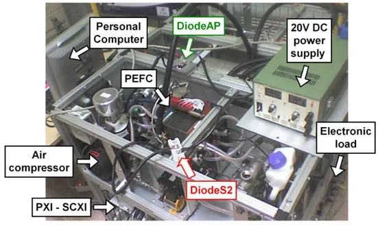
The picture in Fig. 6 shows the experimental test bench with the 500W twenty cell PEFC stack under test integrated in its experimental environment, the reverse Diode AP, the packaging with two diodes in series (Diode S2) with the PEFC and the DC power supply.
4.1.1. Test 1: 5A load current and sudden opening of the contactor in series with the FC
To perform this first test, the diodes in series with the FC (Diode S2) are disconnected. The PEFC operates at 22°C (ambient temperature); the water temperature at the stack outlet gives a good picture of the temperature inside the PEFC assembly. The FC is supplied by dry hydrogen in dead-end mode with flushes at a pressure of 200 [bar rel.] and low humidified compressed air. The water temperature at stack inlet for the cooling of the PEFC is 17°C. The use of such a low temperature level permits to reach a steady-state operation in a very short moment and thus to save time in the experiments. In this first test, the load current reference is set to 5A. However, a current offset (0.3A) is measured by the sensors (LEM1 and LEM2) linked with the FC current and load current due to a low amplitude leakage current flowing in the circuit. During the
steady-state phase, the FC voltage is UFC =15.5V (Fig. 7c) and the FC current IFC =5.3A. The FC power
reaches 82W. The air compressor speed is 400 rpm, and the air flow estimated value of 15
Nl.min-1.
The contactor in series with the FC is switched-off (open) and the Diode AP switches instantaneously into conduction in order to ensure the current continuation to the load. The FC current falls to zero and the Diode AP relieves the load current (green dotted line in Fig. 7b). Then, the electrical contactor is switched-on (closed) once again and the FC delivers the load current. The Diode AP is automatically switched-off.
The temperature of the stack reaches acceptable values. At the end of the test, the FC temperature is close to 21°C. Temperatures are maintained at a nearly constant value during the test. The minimal and maximal FC cell voltages reach acceptable values (minimum 0.6V) also during the transition phases (Fig. 7d).
a b 0 1 2 3 4 5 0 50 100 150 200 250 Time [min] Pres sures at inlet s of FC [m bar r el.] P H2 in P Air in 0 1 2 3 4 5 -1 0 1 2 3 4 5 6 Time [min] Curre nt [A] FC current
Load = current in DC source or battery Current in DiodeAP
Load current reference
c d 0 1 2 3 4 5 15 15.5 16 16.5 17 17.5 18 18.5 19 19.5 Time [min] Volta ge [V ] Voltage of FC 0 1 2 3 4 5 0.55 0.6 0.65 0.7 0.75 0.8 0.85 0.9 0.95 1 Time [min] Cell voltag es of FC [V]
Min cell voltage Max cell voltage
Fig. 7. Diode AP switching for 5A load current and sudden opening of the contactor in series with the FC. (a) Hydrogen and air rel. pressures at inlets; (b) measured currents; (c) measured FC voltage; (d) FC minimal and maximal cell voltages.
4.1.2. Test 2: Break in the air flow feeding the cathode and progressive switching of the Diode AP for a 10A load current amplitude
A preliminary experiment has been initiated using only one of the two diodes (Diode S2) in series with the FC stack, but no conduction of the Diode AP was observed. Thus, the two diodes present in the packaging are connected in series to increase the voltage gap and allow the
The PEFC stack still operates in dead-end mode with purges. The load current is imposed at 10A level and controlled. The air compressor speed is 600 rpm, which corresponds to an air flow
of 25 Nlmin-1. The contactor in series with the FC stack remains closed during the experiment.
The air gas flow is voluntarily stopped by imposing a zero reference on the compressor (acting as an air flow regulator) so that the air pressure at stack inlet falls down to zero (Fig. 8a).
Simultaneously the load current continues to pass through the FC and the stack operates in abnormal condition with insufficient gas supply. The FC voltage decreases consequently to values close to zero Volts and when the Diode AP conduction threshold is reached, the Diode AP switches-on progressively. The dynamic response time of the Diode AP is within a couple of seconds (Fig. 8b). During the next constant phase, the FC power is 154W (15V; 10.3A) (Fig. 8b and 8c). a b 0 1 2 3 4 5 6 7 0 50 100 150 200 250 Time [min] Pres sures at inlet s of FC [m bar r el.] P H2 in P Air in 0 1 2 3 4 5 6 7 -2 0 2 4 6 8 10 12 Time [min] Curre nt [A] FC current
Load = current in DC source or battery Current in DiodeAP
Load current reference
0 1 2 3 4 5 6 7 0 5 10 15 20 Time [min] Volta ge [V ] Voltage of FC 0 1 2 3 4 5 6 7 -0.2 0 0.2 0.4 0.6 0.8 1 1.2 Time [min] Cell voltag es of FC [V]
Min cell voltage Max cell voltage
Fig. 8. Break in the air flow supply; Diode AP switching observed for 10A load current
amplitude. (a) Hydrogen and air rel. pressures at inlets; (b) measured currents; (c) measured FC voltage; (d) FC minimal and maximal cell voltages.
The cell voltages decrease to low values related with starvation phenomenon (Fig. 8d). To avoid such situation and any irreversible damage for the stack, the FC is fed again with air so that its global voltage increases rapidly. Another current switching between the PEFC and Diode AP is realised adopting the same test protocol: stop of the air gas flow by imposing a zero speed reference on the compressor. The air pressure at stack inlet falls to zero [mbar] and the Diode AP switching is achieved successfully.
4.1.3. Test 3: With a 15V DC voltage source and 25A load current amplitude
The voltage of the DC source is now set to constant 15V voltage amplitude. Test 3 is performed for a 25A load current amplitude. In this test the FC power reaches 320W (12.8V, 25A) during the steady-state phase. The power delivered by the DC voltage is 375W (15V, 25A) (Fig. 9b to Fig. 9d). The same operating mode is adopted. The Diode AP switches-on into conduction for a while. The current is shared between the Diode AP and the FC. The Diode AP current reaches around 22A, whereas the FC current reaches 3A during the commutation phase,
taking into account the voltage drop caused by Diode S2. Then the load current reference is decreased to 15A. a b 0 2 4 6 8 0 50 100 150 200 250 Time [min] Pres sures at inlet s of FC [m bar r el.] P H2 in P Air in 0 2 4 6 8 -5 0 5 10 15 20 25 30 Time [min] Curre nt [A] FC current
Load = current in DC source or battery Current in DiodeAP
Load current reference
c d 0 2 4 6 8 -5 0 5 10 15 20 Time [min] Volta ge [V ] Voltage of FC
Voltage of DC source or battery
0 2 4 6 8 -50 0 50 100 150 200 250 300 350 400 Time [min] Electrical power [W] FC power
Power of DC source or battery
e f 0 2 4 6 8 15 20 25 30 35 40 45 Time [min] Temper ature s in FC [° C] T H2 in T Air in T water T ambient 0 2 4 6 8 -0.2 0 0.2 0.4 0.6 0.8 1 1.2 Time [min] Cell voltag es of FC [V]
Min cell voltage Max cell voltage
Fig. 9. Diode AP switching for a 25A load current amplitude and 15V DC voltage supply. (a) Hydrogen and air rel. pressures at inlets; (b) measured currents; (c) measured FC and DC supply voltages; (d) FC and DC supply power; (e) measured temperatures; (f) FC minimal and maximal cell voltages.
The graphics in (Fig. 9e) and (Fig. 9f) show the evolution of the temperatures in the stack as well as minimal and maximal cell voltages during the test. The FC water temperature reaches a peak of 41°C before fault occurrence. At the end of Test 3, the FC impedance is measured at no-load using the Agilent 4338B milliohm meter [27]. The measurement is realised after feeding the anode and cathode respectively with dry hydrogen and low humidified air in order to dry the membranes. The no-load voltage of the stack is 19V. The impedance of the twenty PEFC stack is in the range of 36 to 38mΩ at about 1.5 kHz. This value can be correlated with the resistance
value (Rm) of the stack used for the simulation. Then the PEFC stack is fed normally with gas
reactants and a current reference is imposed to the stack.
4.2. Second experiment: with a 12V Lead-acid battery connected in series with the PEFC
Nowadays, many studies dealing with the topic of electrical coupling between FCs and batteries and with power management strategies between the two devices are carried out [28]. In our study, the set made of the two electro-chemical sources can be considered as a low power twin-source hybrid system. Experimental results will be presented in the following section illustrating the electrical coupling of the 20 cell PEFC with a 12V electrochemical lead-acid battery connected in series.
The battery is a 12V / 4Ah valve regulated lead-acid battery (Yuasa NP4-12). The battery replaces the constant voltage supply used in the previous experiments. The internal resistance of the battery is equal to 40mΩ at 1 kHz. To simplify the scheme of the experimental set-up, the
battery is represented in as an ideal 12V voltage source (Fig. 5.). At the beginning of the tests, the battery is fully charged to 12.4V.
4.2.1. Test 4: PEFC / 12V battery coupling and applying load current regulation
After a gradual step-up, the load current remains controlled at a 5A reference (Fig. 10b). Like for the previous experiments, the air flow is stopped to induce a break in the gas reactant feeding.
The FC voltage decreases and when the conduction threshold (VF) of the Diode AP is reached,
the progressive switching of the reverse diode can be observed. During the experiment the battery is discharged from 12.4V to 11V (Fig. 10c). The power delivered by the battery is around 60W (Fig. 10d). a b 0 1 2 3 4 5 0 50 100 150 200 250 Time [min] Pres sures at inlet s of FC [m bar r el.] P H2 in P Air in 0 1 2 3 4 5 -1 0 1 2 3 4 5 6 Time [min] Curre nt [A] FC current
Load = current in DC source or battery Current in DiodeAP
Load current reference
c d 0 1 2 3 4 5 0 5 10 15 20 Time [min] Volta ge [V ] Voltage of FC
Voltage of DC source or battery
0 1 2 3 4 5 -20 0 20 40 60 80 100 Time [min] Electrical power [W] FC power
Fig. 10. Test with one 12V battery in series with the FC and imposing load current regulation. (a) Hydrogen and air rel. pressures at inlets; (b) measured currents; (c) measured FC and battery voltages; (d) FC and battery delivered power.
4.2.2. Test 5: Power regulation strategy with the coupling PEFC and battery
In this test, the control strategy is modified and the load power is regulated. The power is established by successive power steps (Fig. 11d) until the value of 70W (reaching 30W on the battery and 40W on the PEFC). Then, the air gas flow is stopped and the switching of the Diode AP is progressively achieved (Fig. 11b).
a b 0 1 2 3 4 5 0 50 100 150 200 250 Time [min] Pres sures at inlet s of FC [m bar r el.] P H2 in P Air in 0 1 2 3 4 5 -1 0 1 2 3 4 5 6 7 8 Time [min] Curre nt [A] FC current
Load = current in DC source or battery Current in DiodeAP c d 0 1 2 3 4 5 0 2 4 6 8 10 12 14 16 18 Time [min] Volta ge [V ] Voltage of FC
Voltage of DC source or battery
0 1 2 3 4 5 -10 0 10 20 30 40 50 60 70 80 Time [min] Electrical power [W] FC power
Fig. 11. Test with 12V battery in series with the PEFC and imposing power regulation strategy. (a) Hydrogen and air rel. pressures at inlets; (b) measured currents; (c) measured FC and battery voltages; (d) FC and battery delivered power.
4.2.3. Test 6: Power regulation and opening of the contactor in series with the FC
This test constitutes an identical approach but with the sudden opening of the contactor in series with the FC (Fig. 12a to 12d). During this test, the battery reacts to the transient step and ensures the current continuation. The FC power falls to zero while the battery provides the power to the load. The Diode AP by-pass is automatically achieved.
a b 0 0.5 1 1.5 2 0 50 100 150 200 250 Time [min] Pres sures at inlet s of FC [m bar r el.] P H2 in P Air in 0 0.5 1 1.5 2 -1 0 1 2 3 4 5 6 7 8 Time [min] Curre nt [A] FC current
Load = current in DC source or battery Current in DiodeAP c d 0 0.5 1 1.5 2 10 11 12 13 14 15 16 17 18 19 Time [min] Volta ge [V ] Voltage of FC
Voltage of DC source or battery
0 0.5 1 1.5 2 -10 0 10 20 30 40 50 60 70 80 Time [min] Electrical power [W] FC power
Fig. 12. PEFC / 12V battery coupling, power regulation and contactor opening. (a) Hydrogen and air rel. pressures at inlets; (b) measured currents; (c) measured FC and battery voltages; (d) FC and battery delivered power.
This last test illustrates the dynamic behaviours of both the PEFC and the lead-acid battery in response to a sudden load step. Both sources demonstrate their capabilities to react
complementary to the current perturbation induced.
5. Conclusions
Several experimental tests have been performed in order to analyze the behaviour of a 500W twenty cell PEFC associated with an anti-parallel (reverse) diode (Diode AP) acting as a by-pass to the stack under fault. This technique has already been adopted by industrials for power
applications involving multi-stack FCs. In a first approach, simulations have been performed on a twenty cell PEFC in order to better understand the switching mechanisms and dynamic behaviour of the twenty cell PEFC / Diode AP assembly. Then, various experimental tests were conducted. The PEFC was firstly placed in a series electrical assembly connected to a DC voltage supply, which could emulate a second stack for instance and secondly with a lead-acid battery in order to simulate a hybrid twin-source coupling. The faults which were voluntarily caused on the PEFC stack were a sudden opening of the contactor in series with the FC stack and a break in the gas reactant feeding with a fast decrease of the FC voltage consequently. All the different tests have illustrated the possibility of stack isolation by the anti-parallel diode. However, the switching of the diode is not instantaneous; it depends on both the value of the internal impedance of the FC stack and the load current amplitude. In the experiments, it was therefore necessary to add diodes in series with the FC in order to increase the voltage threshold which leads to the conduction of the anti-parallel diode. The value of the internal resistance of the FC (high frequency resistance of
the membrane) plays a key-role in the triggering of the diode conduction. Anyway the connection of an anti-parallel diode on the plugs of a FC has demonstrated to be a solution which allows operating the FC under degraded working modes and ensures a power delivery continuation in case of a faulty working of the FC.
References
[1] P. Corbo, F. Migliardini, O. Veneri, Experimental analysis and management issues of a hydrogen fuel cell system for stationary and mobile application, Energy Conversion and Management. 48(8) (2007) 2365-2374.
[2] J. Van Mierlo, G. Maggetto, Ph. Lataire, Which energy source for road transport in the future? A comparison of battery, hybrid and fuel cell vehicles, Energy Conversion and Management. 47(17) (2006) 2748-2760.
[3] B. Ozpineci, Z. Du , Leon M. Tolbert, Donald J. Adams, Donald Collins, Integrating multiple Solid Oxide Fuel Cell Modules. In: IEEE IECON Industrial Electronics Conference, 2-6
November 2003, Roanoke, Virginia, pp. 1568-1573.
[4] Knights, Shanna D, De Vaal, Jacob W, Lauritzen, Michael V, Wilkinson, David P,
Electrochemical fuel cell stack having a plurality of integrated voltage reversal protection diodes, US Patent 7235315 issued on June 26, 2007.
[5] Victor W. Logan, James W. Dandalides, System stack contingency and efficiency switching, (US 2004/0202901 A1) Publication date: 14 October 2004.
[6] V. Paladini, T. Donateo, A. De Risi, D. Laforgia, Super-capacitors fuel-cell hybrid electric vehicle optimization and control strategy development, Energy Conversion and Management. 48(11) (2007) 3001-3008.
[7] M. Uzunoglu, MS. Alam, Dynamic modeling, design and simulation of a PEM fuel cell/ultra-capacitor hybrid system for vehicular applications, Energy Conversion and Management. 48(5) (2007) 1544-1553.
[8] MJ. Kim, H. Peng, Power management and design optimization of fuel cell/battery hybrid vehicles, Journal of Power Sources. 165 (2007) 819-832.
[9] Strasser K. PEM Fuel Cell module for an air independent propulsion system in a submarine,
Handbook of Fuel Cells – Chapter 88 H2/02 – PEM. J. Wiley&Sons; 2003, pp 1202-1214.
[10] Lersch Josef, Mattejat Arno. Patents of SIEMENS AG: WO0245197 and DE10059392, Direct-current power supply device comprising a number of series-connected fuel cell blocks; 2002.
[11] D. Candusso, A. De Bernardinis, M-C. Péra, F. Harel, X. François, D. Hissel, G. Coquery, J.M. Kauffmann, Fuel cell operation under degraded working modes and study of a diode by-pass circuit dedicated to multi-stack association, Energy Conversion and Management. 49(4) (2008) 880-895.
[12] P. Coddet, M-C. Péra, D. Candusso, D. Hissel, Study of Proton Exchange Membrane Fuel Cell safety procedures in case of emergency shutdown, In: IEEE ISIE 2007, Vigo, Spain, pp. 725-730.
[13] Engin Karatepe, Takashi Hiyama, Mutlu Boztepe, Metin Çolak, Voltage based power compensation system for photovoltaic generation system under partially shaded insolation conditions, Energy Conversion and Management. 49(8) (2008) 2307-2316.
[14] Lasich, John, Beavis. Bypass diode for photovoltaic cells, Patent Pub. No. WO/2004/102678, publication date: 25 November 2004.
[15] Balasubramanian S, Berke H, Coakley K, Scharber M. Photovoltaic cells integrated with bypass diode, Patent Pub. No.: WO/2007/028036, Publication Date: 08 March 2007.
[16] R. Messenger, J. Ventre, Photovoltaic Systems Engineering, CRC Press, 1999.
[17] B. Multon, Photovoltaic Generation, Lecture at ENS Cachan, 2005, ISBN: 2-909968-69-3. [18] Yoshioka H, Nishikawa S, Nakajima S, Asai M, Takeoka S, Matsutani T, Suzuki A. Non hot-spot PV module using solar cells with bypass diode function. Photovoltaic
Specialists Conference 1996. Conference Record of the Twenty Fifth IEEE, 13-17 May 1996, pp. 1271 – 1274.
[19] MATLABTM Software, The MathWorksTM, Inc. 2007, <http://www.mathworks.com/>
[20] Taniguchi Akira, Akita Tomoki, Yasuda Kazuaki, Miyazaki Yoshinori, Analysis of electrocatalyst degradation in PEMFC caused by cell reversal during fuel starvation, Journal of Power Sources. 130 (2004) 42-49.
[21] Liu Zhixiang, Yang Lizhai, Mao Zongqiang, Zhuge Weilin, Zhang Yangjun, Wang Lisheng, Behavior of PEMFC in starvation, Journal of Power Sources. 157(1) (2006) 166-176.
[22] Garnier James, Association en parallèle de générateurs pile à combustible PEMFC (Parallel association of PEM fuel cells generators), Thèse de doctorat (Ph.D thesis), in French, University of Technology Belfort Montbéliard (UTBM) / University of Franche Comté (UFC) – Belfort France, 20 June 2006.
[23] Harel Fabien, Expérimentations de piles à combustible en approche système embarqué (Experiments on fuel cells in embedded system approach), INRETS LTE Internal Report Nr. 0802, in French, Belfort, France, edited in January 2008.
[24] ZSW-UBzM Company website: <http://www.zsw-bw.de/index.html/>, 2009.
[25] Data-sheet Fast Recovery Epitaxial Diode (FRED) DSEI 2x 61. IXYS, 2000, website: <http://www.ixyspower.com/>.
[26] Data-sheet power IGBT/Diode module - SKM 75GB123D. SEMIKRON, 11-09-2006, website: <http://www.semikron.com/>.
[27] Agilent 4338B MilliohmMeter Technical Overview, Agilent Technologies Inc., Printed in USA, April 10, 2008, website: <http://www.agilent.com/find/lcrmeters/>.
[28] A. Jossen, J. Garche, H. Doering, M. Goetz, W. Knaupp, L. Joerissen, Hybrid systems with lead–acid battery and proton-exchange membrane fuel cell, Journal of Power Sources. 144(2) (2005) 395-401.