HAL Id: hal-02997481
https://hal.archives-ouvertes.fr/hal-02997481
Submitted on 23 Nov 2020
HAL is a multi-disciplinary open access
archive for the deposit and dissemination of
sci-entific research documents, whether they are
pub-lished or not. The documents may come from
teaching and research institutions in France or
abroad, or from public or private research centers.
L’archive ouverte pluridisciplinaire HAL, est
destinée au dépôt et à la diffusion de documents
scientifiques de niveau recherche, publiés ou non,
émanant des établissements d’enseignement et de
recherche français ou étrangers, des laboratoires
publics ou privés.
Optomechanical resonating probe for very high
frequency sensing of atomic forces
Pierre Etienne Allain, Lucien Schwab, Colin Mismer, Marc Gely, Estelle
Mairiaux, Maxime Hermouet, Benjamin Walter, Giuseppe Leo, Sébastien
Hentz, Marc Faucher, et al.
To cite this version:
Pierre Etienne Allain, Lucien Schwab, Colin Mismer, Marc Gely, Estelle Mairiaux, et al..
Optome-chanical resonating probe for very high frequency sensing of atomic forces. Nanoscale, Royal Society
of Chemistry, 2020, 12 (5), pp.2939-2945. �10.1039/c9nr09690f�. �hal-02997481�
Optomechanical Resonating Probe for Very High Frequency Sensing of
Atomic Forces
Pierre Etienne Allain
a, Lucien Schwab
b, Colin Mismer
c, Marc Gely
d, Estelle Mairiaux
e, Maxime Hermouet
d,
Benjamin Walter
e, Giuseppe Leo
a, Sébastien Hentz
d, Marc Faucher
c, Guillaume Jourdan
d, Bernard
Legrand
b, and Ivan Favero
a†Atomic force spectroscopy and microscopy are invaluable tools to characterize nanostructures and biological systems. State-of-the-art experiments use resonant driving of mechanical probes, whose frequency reaches the MHz in the fastest commercial instruments where cantilevers are driven at nanometer amplitude. Stiffer probes oscillating at tens of picometers provide a better access to short-range interactions, yielding images of molecular bonds, but they are little amenable to high-speed operation. Next-generation investigations demand combining very high frequency (>100MHz) with deep sub-nanometer oscillation amplitude, in order to access faster (below microsecond) phenomena with molecular resolution.Here we introduce a resonating optomechanical atomic force probe operated fully optically at a frequency of 117 MHz, two decades the above cantilevers, with a Brownian motion amplitude four orders below. Based on a Silicon-On-Insulator technology, the very high frequency probe demonstrates single-pixel sensing of contact and non-contact interactions with sub-picometer amplitude, breaking open current locks for faster and finer force spectroscopy.
1. Introduction
The possibility to measure and investigate physical forces at the nanoscale and below has been a turning point in the evolution of science and technology. Atomic Force spectroscopy and Microscopy (AFM) have regularly gained in functionality, precision and speed, impacting at large soft and condensed matter science, chemistry and biology1-10.In recently developed and commercialized high-speed
AFMs (HS-AFMs), the dimensions of a vibrating cantilever are reduced until they reach the diffraction limit of the optical detection spot. At that point, the lever’s flexural frequency reaches the MHz range, hence time resolution down to the microsecond, while video-rate scanning force imaging is achieved4,8. In order to ensure large
signal-to-noise in force detection, these probes are resonantly driven at around a nanometer of amplitude, well above their Brownian motion but also well above interatomic distances, hindering the optimal investigation of short-range interactions1,2,4,8. In contrast,
stiffer probes e.g. based on quartz resonators can resonantly operate at oscillation amplitude of tens of picometers. They hence favour the contribution of short-range atomic forces and yield sufficient resolution to image molecular bonds3,9,10. However, as the probe
stiffens and the oscillation amplitude decreases, more efficient transduction and actuation of mechanical motion are required, and
in consequence functional stiff probes for atomic forces have not been applicable to high-speed sensing11,12, be it on a single-pixel
without surface scanning. In summary, current oscillating probes for atomic force spectroscopy and microscopy do not access physical phenomena below the microsecond, while the few that approach this time-scale cannot resolve molecular scale interactions. The difficulty in bringing together temporal and spatial resolutions limits the investigation of fast phenomena at the microscopic level. Probes that would combine a much faster oscillation (100 MHz and beyond) with deep sub-nanometer amplitude might open a new avenue for resonant force sensing, be it single-pixel spectroscopy or imaging. They would indeed broaden experimental access to physical dimensions and timescales routinely amenable to molecular dynamic simulations13 (micro to nanosecond), hence enlarging our
understanding of chemical and biological reactions at the molecular level.
Here, we show that a convergence of optimized photonics, optomechanics and MEMS/NEMS technologies, based on a silicon platform, meets the above requirements. We demonstrate a very high-frequency (100MHz<f<300MHz) oscillating ring-shaped probe that senses local forces exerted on its nanoscale apex. Fully optically actuated and detected thanks to a strong tailored optomechanical coupling, the probe uses a very high-frequency stiff contour mechanical mode, reaching a frequency 2 decades above cantilevers of the fastest commercial AFM instruments, with a Brownian motion amplitude 4 orders below. We demonstrate the operability of the probe by performing single-pixel sensing of both contact and non-contact forces in the resonantly driven oscillating mode. We show that dissipative like non-dissipative interactions can be measured at ultra-low amplitude of motion, and that the bandwidth of the force measurement is merely set by the mechanical response of the probe. Our results indicate that the approach could be expanded to the GHz frequency range.
a.Matériaux et Phénomènes Quantiques, Université de Paris, CNRS UMR 7162,
Paris, France.
b.Laboratoire d’Analyse et d’Architecture des Systèmes, CNRS UPR 8001, Université
de Toulouse, Toulouse, France.
c. Institut d'Electronique, de Microélectronique et de Nanotechnologie, Université
de Lille, CNRS UMR 8520, Lille, France.
d.Université Grenoble Alpes, CEA, LETI, Minatec Campus, Grenoble, France. e.Vmicro SAS, Avenue Poincaré, Villeneuve d'Ascq, France.
2
2. Results and discussion
Operating principle and implementation
In the oscillating mode, where noise rejection is optimal, both speed and amplitude are impacted by a same chief parameter: the resonant frequency f of the mechanical probe. The force signal is obtained by tracking f, which can be done within a bandwidth between f/Q (with Q the probe’s quality factor) and f 14,15. At the
same time, f directly connects to the amplitude of Brownian motion, which decreases as the probe stiffens. Very high frequency mechanical probes (>100 MHz), much smaller and/or stiffer than standard probes and nanowires16-20, would hence be a solution to
combine speed and spatial resolution beyond current limitations. They are however difficult to control with standard techniques, like integrated electromechanical transduction21,22 or optical spot
detection, and a larger coupling between mechanical motion and transducer/actuator would be required to achieve this goal. Optomechanical transduction was recently implemented for AFM cantilevers23,24, but with a moderate coupling that limited force
experiments to MHz probes. Direct actuation and detection in the resonant oscillating mode still constitutes a challenge for much higher frequency probes. These problems are solved in the sensing device introduced here.
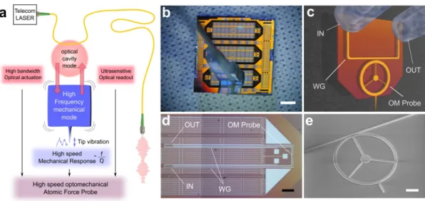
The working principle of our optomechanical atomic force probe is illustrated in Figure 1a. The probe resonator vibrates along a very high frequency and stiff extensional (bulk) mechanical mode, which sets an apex into a quasi-1D oscillation. The vibration is actuated through forces generated by the optical field stored in a laser-driven high-Q cavity, which is optomechanically coupled to the probe. The apex-to-surface elastic and dissipative interactions modulate the mechanical vibration, which is in turn transduced to the optical cavity mode. This all-optical operation of the probe allows a large-bandwidth actuation and readout of motion, as well as the use of low-noise lasers and optical amplifiers that result in advantageous noise management. In what follows, these assets translate into the capability to drive the very high-frequency (>100 MHz) probe with sub-picometer motion amplitude, with a detection merely limited by thermomechanical noise. To facilitate device applications, chips hosting the probes are fabricated on a Silicon-On-Insulator (SOI) platform using a very large scale integration (VLSI) process derived from silicon photonics (Figure 1b), completed by an under-etching of the sacrificial oxide. Input and output light is injected and collected through grating-couplers into an on-chip optical waveguide evanescently coupled to the optomechanical probe (Figure 1c-d)25,26.
The probe itself takes the form of a silicon ring suspended on a central post through spokes, which enables intense optomechanical coupling between light travelling within the ring and the extensional modes of the structure27,28. The nano-machined probe apex sensing
forces is diametrically opposed to the evanescent coupling region. The apex protrudes away from the silicon ring (Figure 1c, 1e), allowing near-field physical interactions with objects under test. Figure 1 Introduction of the very high speed optomechanical atomic force probe. a, A high-Q optical cavity mode resonating in the telecom
range is coupled to a very high frequency extensional mechanical mode. The latter is optically actuated and read-out, and has fast response to forces exerted onto the apex. b, VLSI-fabricated boat-shaped probe devices positioned in parallel on a chip, and detachable by back-etching. All devices are identical and embed one probe and its optical operation circuitry. Scale bar: 2 mm. c, Simplified 3D rendering of the structure highlighting the protruding apex of the optomechanical (OM) probe, the waveguide (WG) and the fiber grating couplers (IN and OUT). d, Zoomed optical image of a fabricated boat-shaped device. Scale bar: 300 µm. e, SEM micrograph of the optomechanical probe characterized in this letter. Scale bar: 2 µm.
3
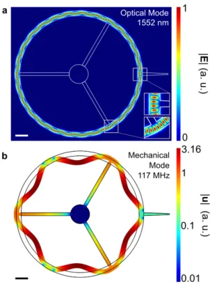
The detailed design of the optomechanical ring is shown in Figure S1 of the Supplementary Information (ESI). We choose a large enough ring radius (10 µm) to facilitate back etching of the underlying substrate and eventually allow the probe apex to protrude from the device, while we choose a ring thickness compatible with photonics standards (220 nm). The selected ring structure supports localized optical and mechanical modes (Figure 2), which optomechanically couple via radiation pressure at a rate
g0~72 kHz29,30, as well as via photothermal effects31,32. The high-Q
optical mode deviates from a standard whispering gallery mode and has instead a serpentine trajectory in the azimuthal direction (Figure 2a). This specific structure allows positioning the bases of the apex and spokes in areas where the electromagnetic energy is minimized, greatly mitigating scattering optical losses in the functional design (Insets in Figure 2a). This positioning is well-controlled and reproducible thanks to a ~10 nm fabrication precision, smaller than the optical and mechanical wavelengths. The optical mode is engineered to resonate in the telecom C-band, with a wavelength around 1550 nm. Finite element simulations predict a radiative optical Q0 of a few 105, while experiments reveal an upper limit of
Q0~105 with our current technology. For narrow enough apex and
spokes, the optical losses are likely due to residual surface imperfections, while for wider ones (wapex>500 nm, wspk>500 nm), geometrical scattering losses contribute to a degradation of Q0 below 105. The resonating wavelength and loaded quality factor of the
mode employed hereafter are λ0=1552 nm and Qloaded~7´104.
The mechanical mode is designed to maximize optomechanical coupling, as well as to reach very high frequency and thermomechanical motion well below the picometer. The radial breathing (contour) mode of the ring qualifies for these three criteria. Like the optical mode, it possesses an azimuthal modulation as a consequence of the anchoring by the spokes (Figure 2b). Its measured frequency is f~117 MHz, consistent with numerical simulations, while the quality factor is measured to amount to
Q~2790 in vacuum. To explore the versatility of our probe design,
smaller probes with a mechanical frequency of 262 MHz, as well as probes of smaller stiffness, have been characterized and are discussed in Figure S2 of the Supplementary Information.
All-optical control of the resonating probe
To optically actuate the probe vibration, the light injected into the resonator is amplitude-modulated at a frequency fd close to f by means of an electro-optical modulator (EOM) driven with an RF-voltage of amplitude Vd. The light exiting the resonator, which conveys information about the mechanical motion, is detected by a fast photodetector and amplified before being fed to a lock-in amplifier (LIA). The corresponding block-diagram is detailed in Figure S3 of the Supplementary Information. The magnitude R1 of the signal vector, which is proportional to the mechanical motion amplitude, is recorded while sweeping fd around f for several values of Vd (Figure 3a). At Vd = 0 V, the Brownian motion of the probe is detected more than 10 dB above the displacement noise floor at a few 10-17 m/√Hz
(not shown), which indicates that residual noise in the resonant oscillating mode is dominantly thermo-mechanical in nature. In the driven mode (Vd ≠ 0 V), the resonant vibration amplitude of the probe apex ranges from 0.1 fm to near 1 pm for the selected mechanical mode at 117 MHz, and scales linearly with the driving voltage Vd (Figure 3b). Those small amplitudes, much smaller than interatomic distances, are a key to non-perturbative probe-matter interactions, and result from the large effective spring constant at the selected apex location. A calibration factor of 2.5 mV/pm converting the probe motion amplitude to the voltage output by the LIA was deduced by using the observed linearity of the measurement chain and fitting the Brownian motion noise power spectrum of the mode with known parameters: temperature T=300 K and effective spring constant k~2.6x10⁶ N/m. The measured dynamic range between the
Brownian and the maximally driven motion amounts to 75 dB. In a driven operation mode near resonance fd~f and under vacuum (10-5 mbar), we characterize the performances of the probe by
monitoring during 200 s the normalized shift of mechanical frequency Δf/f = (f-f0)/f0, with f0 the unperturbed mechanical frequency (see Methods). The Allan deviation of Δf/f is showed in Figure 3c. For integration times below 10s, its time-dependence is consistent with the dominance of thermo-mechanical noise. At 10 s integration time, a relative deviation Δf/f~10-7 is routinely reached.
After 10 s, experimental drifts increase the frequency noise. Figure 2: Optical and mechanical modes of the optomechanical probe.
a, Map of the normalized modulus of the electric field showing the spatial
distribution of the optical cavity mode (λ0=1552 nm, Q0~105). Insets:
spokes and probe apex are anchored to the ring at low field density areas, thereby minimizing scattering optical losses. b, Modulus of the displacement of the mechanical mode employed in this study (f =117 MHz). The probe apex is displaced along its longitudinal axis, as the result of the mode’s symmetry. Scale bars: 2 µm.
4
Sensing of contact and non-contact forcesNext we perform a benchmark approach-retract cycle (Figure 4a), in a “single-pixel” configuration (no surface scanning), where the probe apex is approached to the tip of a separate µm-sized commercial cantilever while the probe frequency variations Δf=(f-f0) are
monitored in a phase locked loop configuration (close-loop mode, see Supplementary Information and Figure S3). Note that in such configuration the force gradient is measured in place of the force. If needed, the latter is obtained by spatial integration of the former, up to a constant. The resulting force (gradient) curve is reported in Figure 4b, as function of the motion of the piezo holding the lever. A typical hysteresis cycle is evidenced33. In this proof-of-principle
experiment the probe is voluntarily brought close enough that its apex snaps in and out of the cantilever tip as it is approached and retracted, revealing large adhesion forces between the apex and the gold-coated cantilever, where a water meniscus is probably forming. As the probe snaps in, the normalized frequency abruptly varies by 150 ppm over a distance smaller than 0.1 nm. With the normalized Allan deviation of 0.1 ppm measured in Fig. 3, this implies a potential resolution of displacement below 0.1 pm. As the probe snaps-out, the frequency correctly comes back to the starting value at the beginning of the cycle. The mechanical mode frequency response has been acquired independently under contact and non-contact conditions (Figure 4b inset), showing a frequency shift that corresponds to that measured during the approach-retract cycle. While in contact, the mechanical Q-factor experiences a 4-fold decrease compared to non-contact, which indicates that dissipative contact interactions can also be sensed.
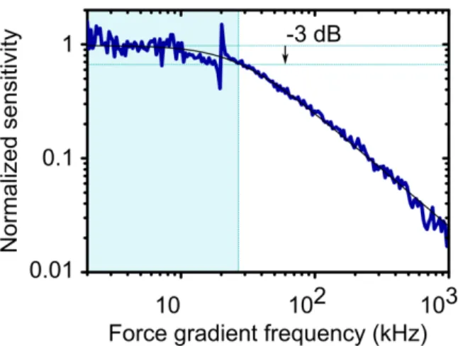
To finally demonstrate the bandwidth of the optomechanical force probe, a time-modulated electrostatic force, inducing a
time-modulated force gradient, is generated between the probe apex and the cantilever tip by applying a modulated voltage at frequency fForce between them. The tip is positioned a few nanometers before contact and while the modulation frequency is scanned from 2 kHz to 1 MHz, we measure the probe vibration amplitude in response to this stimulation. The frequency response of the probe is shown in Figure 5. The response is flat up to a cut-off frequency of 26 kHz, of order Γ, the invert of the relaxation time corresponding to the measured mechanical Q~2790 (Γ= 2πf/Q). This demonstrates that the bandwidth is merely limited by the mechanical response of the device. With the here employed measurement protocol, the bandwidth of the force measurement is indeed expected close to f/Q, but in other protocols it can in principle approach f14,15.
In recent work, we demonstrated that disk-shaped optomechanical resonators similar to the here reported probes are efficiently operated in liquids with a Q below of a few units to ten 34,35. With the here-employed force sensing protocol, this
implies a measurement bandwidth already beyond 10 MHz. While Q can be controlled by tuning the size of the pedestal36,37,
by implementing a feedback control, or by operating in a liquid34,35, it is really the probe frequency that eventually sets
the perspective in terms of force bandwidth. Our results show that it can be pushed to the very high frequency range (>100 MHz) with the here-reported optomechanical approach, indicating that GHz is within reach.
Figure 4. Optomechanical probe driving and characterization. a, Optomechanical probe apex vibration amplitude measured from the Brownian motion regime (plotted with a thicker line, BW=1 Hz) to larger driven amplitudes, with an EOM driving voltage
Vd evolving between 1.5 and 750 mV. b, Resonant amplitude of the vibration of the
apex versus drive voltage Vd showing linearity along the dynamical range. c,
Normalized Allan deviation of the mechanical frequency Δf/f as a function of the analysis time t (open loop).
Figure 3. Approach-retract experiment. a, Optical photography of the commercial cantilever tip approaching the optomechanical (OM) probe (left panel). The experiment is performed under vacuum. Scale bar: 20 µm. Schematic of the experiment where the cantilever tip is in contact (middle panel) and non-contact (right panel), WG: optical waveguide. b, Normalized mechanical frequency shift versus the motion of the piezo holding the tip, in an approach-retract cycle. A blue zone is indicated that corresponds to non-contact conditions. Inset: difference of frequency and mechanical Q-factor in contact (red) and non-contact (blue).
5
DiscussionIn summary, we have developed a new mechanical atomic force probe that operates in sub-picometer oscillating mode at frequencies above 100 MHz, decades above probes employed in state-of-the-art commercial HS-AFM instruments. The strong optomechanical coupling enables all-optical operation of the probe, both in vibration actuation and detection. This permits low-noise force acquisition in the mechanically oscillating mode, which is of utmost importance for high-resolution experiments thanks to rejection of out-of-resonance noise sources. The strong coupling also translates into an advantageous optical transduction, with displacement sensitivity down to 10-17m/√Hz, giving room for a large
dynamic range merely limited by thermomechanical noise.
With this resonating probe and its nanoscale tip-shaped apex, we have demonstrated “single-pixel” sensing of contact forces as well as of fast electrostatic interactions. Our results validate the optomechanical approach for tip force sensing but also indicate that the frequency, and hence optimally the force bandwidth, could be pushed up to the GHz with optimized versions of the probe27,28, a range that has remained out of
reach of mechanical sensing at small scale. An application would be AFM imaging at higher speed. Indeed the concept demonstrated here on a single-pixel already unlocks limitations associated to current cantilevers, even if more rapid positioners and feedback electronics will be required to fully explore a scanning application with close-to-GHz probes. At the single pixel level, many investigations already become accessible with such very high frequency probes and their potential bandwidth. This spans condensed matter, where the dynamics of domains in glass-forming bodies and of vortices in superconductors could be tracked; and biology, where local motions of complexes in ligand binding or protein folding13 could be
resolved at time-scales shorter than the microsecond. At the molecular level, the ultra-fast spectroscopy of dissipation may also better elucidate relations between conformation and function.
Conflicts of interest
“There are no conflicts to declare”.
Acknowledgements
The authors thank Eduardo Gil-Santos and Denis Lagrange for discussions. The authors acknowledge support from the French Agence Nationale de la Recherche through the Olympia ANR-14-CE26 0019 and QuaSeRT ANR-18-QUAN-0006 projects, and from the French DGA. P. E. Allain and I. Favero were supported by the European Research Council through the GANOMS n°306664 and NOMLI n°770933 projects, and by the FET program through the VIRUSCAN project n°731868.
Author Contributions
S. H, M. F, G. J, B. L and I. F launched the project. P. E. A. and L. S. carried systematic sensing measurements. P. E. A, G. L, S. H, M. F, G. J, B. L and I. F led the design of the probe. P. E. A, C. M, M.G, E. M, M. H, B. W, M. F and G. J carried the lithography and probes fabrication, together with intermediate characterization steps. P. E. A., L. S., S. H, M. F, G. J, B. L and I. F discussed the data. All authors contributed to the manuscript, under the guidance of P. E. A., L. S., B. L and I. F.
Notes and references
Device Fabrication. The optomechanical resonators and waveguides were
patterned from a SOI wafer with e-beam lithography followed by an inductively coupled plasma reactive ion etching (ICP-RIE) step. Electron dosage was fine-tuned to compensate proximity effects. For some devices, the die was cleaved at a distance of 1 mm from the resonator to terminate the waveguides and provide optical coupling conditions at the cleaved facets. Finally, the resonators were released by HF vapor etching of the buried silicon oxide layer. Images of devices fabricated using the VLSI technology can be found in Figure S4 of the Supplementary Information. The fabrication process is compatible with the future implementation of a sharp probe apex compatible with atomic resolution of forces38.
Design. For simplicity, the apex has been diametrically opposed to the spokes
but it can be positioned differently if willing to increase its displacement while reducing its stiffness (see Supplementary Information). In Figure 2a’s design, the simulated spring constant of the resonator taken at the apex reduction point is k~2.6x10⁶ N/m. If the spokes are rotated 30o anticlockwise, the spring
constant is k~4 kN/m while the high optical quality factor is preserved.
Optical driving of the probe. Electro-Optical Modulators were operated to
have a sinusoidal response to the applied voltage. A maximal driving voltage of 750 mV was chosen to remain in the linear regime and hinder harmonics generation. The transmission of such modulator being sensible to temperature, the latter was regulated. In order to actuate effectively the mechanical motion, the optical wavelength was set practically at resonance to the optical mode.
Measurement of the frequency shift deviation. See Figure S3 of the
Supplementary Information for definitions. To estimate the frequency shift Δf without locking, the phase ϴ1 between the drive signal and the resonator
response, extracted from the signal vector exiting the LIA, was converted to the frequency knowing in advance the slope of the phase rotation versus drive frequency: α = 4.42 10-4 °/Hz. The measured frequency shift was thus Δf/f =
(ϴ1 - ϴ1_initial)×α/f0.The driving voltage was set to 200 mV and the LIA filter BW
was set to 100 kHz. As expected from white noise limited experiment, the deviation scaled as τ-1/2 in the region τ < 10 s.
Figure 5. Normalized frequency response of the probe amplitude to a modulated electrostatic force gradient. The measurement shows a low-pass filter behaviour with cut-off at 26 kHz.
6
Force Curve experiment. Gold was sputtered on the cantilever tip and the
gold layer was wire-bonded to remotely set its electrical potential. In phase-locked loop configuration, the measured frequency shift is Δf/f = (f- f0)/f0 with
f = fd.
Frequency response to an external force gradient. A modulated (from 2 kHz
to 1 MHz) electric potential was applied to the golden tip. For the whole experiment, the probe was driven at its maximum amplitude (Vd =750 mV @
117 MHz). To ensure that the response of the probe amplitude was purely electrostatic and not interfered by other electrical or opto-electrical phenomena, the demodulated signal R2eiϴ2 (see Figure S3) was acquired in
two configurations: I) R2_IN eiϴ2_IN: on the flank of the mechanical mode
amplitude of maximum slope with fd = f0 – (Γ/2π)/2; II) R2_OUT eiϴ2_OUT: far from
the mechanical resonance with fd = f0 – 65´ Γ. Finally the normalized transfer
function H_LPF of the demodulation low pass filter of Lock-in 1 (BW= 500 kHz)
was acquired. The low pass filter compensated probe amplitude was then |(R2_IN eiϴ2_IN - R2_OUT eiϴ2_OUT)/H_LPF|. We checked that the measurement chain
bandwidth (cables, photodetector) was much higher than 1 MHz. The “Fano-like” peak at 20 kHz is interpreted as a mechanical mode of the cantilever.
Supplementary Information
The Supplementary Information contains 4 figures and 1 table. Figure S1 details the probe design. Figure S2 reports on a higher frequency device at 263 MHz. Figure S3 details the experimental set-up, while Figure S4 details the probe fabrication. Table S1 is a reader’s guide to Figure S3.
1 F. J. Giessibl, Atomic Resolution of the Silicon (111)-(7x7)
Surface by Atomic Force Microscopy, Science, 1995, 267, 68–71.
2 R. Garcia, C. J. Gómez, N. F. Martinez, S. Patil, C. Dietz and
R. Magerle, Identification of Nanoscale Dissipation Processes by Dynamic Atomic Force Microscopy, Phys.
Rev. Lett., 2006, 97, 016103.
3 L. Gross, F. Mohn, N. Moll, P. Liljeroth and G. Meyer, The
Chemical Structure of a Molecule Resolved by Atomic Force Microscopy, Science, 2009, 325, 1110–1114.
4 N. Kodera, D. Yamamoto, R. Ishikawa and T. Ando, Video
imaging of walking myosin V by high-speed atomic force microscopy, Nature, 2010, 468, 72–76.
5 T. Uchihashi, Y. Watanabe, Y. Nakazaki, T. Yamasaki, H. Watanabe, T. Maruno, K. Ishii, S. Uchiyama, C. Song, K. Murata, R. Iino and T. Ando, Dynamic structural states of ClpB involved in its disaggregation function, Nat.
Commun., 2018, 9, 1, 2147.
6 D. Martin-Jimenez, E. Chacon, P. Tarazona and R. Garcia,
Atomically resolved three-dimensional structures of electrolyte aqueous solutions near a solid surface, Nat.
Commun., 2016, 7, 12164.
7 B. W. Hoogenboom, in Encyclopedia of Nanotechnology
(Springer) 83–89 (2012).
8 T. Uchihashi, N. Kodera and T. Ando, Guide to video
recording of structure dynamics and dynamic processes of proteins by high-speed atomic force microscopy, Nat.
Protoc, 2012, 7, 1193–1206.
9 S. Hembacher, F. J. Giessibl, J. Mannhart and C. F. Quate,
Local Spectroscopy and Atomic Imaging of Tunneling Current, Forces, and Dissipation on Graphite, Phys. Rev.
Lett., 2005, 94, 056101.
10 D. S. Wastl, A. J. Weymouth and F. J. Giessibl, Optimizing
atomic resolution of force microscopy in ambient conditions, Phys. Rev. B, 2013, 87, 245415.
11 J. P. Froning, D. Xia, S. Zhang, E. Lægsgaard, F.
Besenbacher, and M. Dong, Piezoelectric oscillation sensor based noncontact atomic force microscope for imaging in both ambient and liquid environments, J. Vac. Sci.
Technol., 2015, B 33, 021801.
12 T. An, T. Eguchi, K. Akiyama and Y. Hasegawa,
Atomically-resolved imaging by frequency-modulation atomic force microscopy using a quartz length-extension resonator,
Applied Physics Letters, 2005, 87, 13, 133114.
13 K. Henzler-Wildman and D. Kern, Dynamic personalities of
proteins, Nature, 2007, 450, 964–972.
14 E. Rubiola, Phase noise and frequency stability in
oscillators, Cambridge University Press (2008).
15 T. R. Albrecht, P. Grütter, D. Horne and D. Rugar,
Frequency modulation detection using high-Q cantilevers for enhanced force microscope sensitivity, Journal of
Applied Physics, 1991, 69, 2, 668-673.
16 I. Favero, S. Stapfner, D. Hunger, P. Paulitschke, J. Reichel, H. Lorenz, E. M. Weig and K. Karrai, Fluctuating nanomechanical systems in a high finesse optical microcavity, Opt. Exp., 2009, 15, 12813.
17 A. Gloppe, P. Verlot, E. Dupont-Ferrier, A. Siria, P. Poncharal, G. Bachelier, P. Vincent and O. Arcizet, Bi-dimensional nano-optomechanics and topological back-action in a non-conservative radiation force field, Nat.
Nanotechnol., 2014, 9, 920.
18 N. Rossi, F. R. Braakman, D. Cadeddu, D. Vasyukov, G. Tütüncüoglu, A. Fontcuberta i Morral and M. Poggio, Nat.
Nanotechnol., 2017, 12, 150.
19 C. Belacel, Y. Todorov, S. Barbieri, D. Gacemi, I. Favero and C. Sirtori, Optomechanical THz detection with a single
meta-atom resonator, Nat. Commun., 2017,8, 1578.
20 F. R. Braakman and M. Poggio, Force sensing with nanowire cantilevers, Nanotechnology, 2019, 30, 332001.
21 K. Ekinci, Electromechanical Transducers at the Nanoscale:
Actuation and Sensing of Motion in
Nanoelectromechanical Systems (NEMS), Small, 2005, 1, 786–797.
22 B. Legrand, D. Ducatteau, D. Théron, B. Walter and H.
Tanbakuchi, Detecting response of
microelectromechanical resonators by microwave reflectometry, Appl. Phys. Lett., 2013, 103, 53124.
23 K. Srinivasan, H. Miao, M. T. Rakher, M. Davanço and V.
Aksyuk, Optomechanical Transduction of an Integrated Silicon Cantilever Probe Using a Microdisk Resonator,
Nano Lett., 2011, 11, 791–797.
24 J. Chae, S. An, G. Ramer, V. Stavila, G. Holland, Y. Yoon, A.
A. Talin, M. Allendorf, V. Aksyuk, A. Centrone, Nanophotonic Atomic Force Microscope Transducers Enable Chemical Composition and Thermal Conductivity Measurements at the Nanoscale, Nano Lett., 2017, 17, 5587–5594.
25 G. S. Wiederhecker, L. Chen, A. Gondarenko and M. Lipson.
Controlling photonic structures using optical forces.
Nature, 2009, 462, 633–636.
26 C. Baker, C. Belacel, A. Andronico, P. Senellart, A. Lemaître, E. Galopin, S. Ducci, G. Leo and I. Favero, Critical optical coupling between a GaAs disk and a nanowaveguide suspended on the chip, Appl. Phys. Lett., 2011, 99, 151117. 27 L. Ding, C. Baker, P. Senellart, A. Lemaître, S. Ducci, G. Leo
and I. Favero, Wavelength-sized GaAs optomechanical resonators with gigahertz frequency, Appl. Phys. Lett.,
2011, 98, 113108.
28 X. Sun, X. Zhang and H. X. Tang, High-Q silicon
optomechanical microdisk resonators at gigahertz frequencies, Appl. Phys. Lett., 2012, 100, 173116.
29 I. Favero and K. Karrai, Optomechanics of deformable
optical cavities, Nat. Phot., 2009, 3(4), 2001.
30 M. Aspelmeyer, T. J. Kippenberg and F. Marquardt, Cavity
optomechanics, Rev. Mod. Phys., 2014, 86, 1391-1452.
31 C. H. Metzger and K. Karrai, Cavity cooling of a microlever,
7
32 C. Metzger, M. Ludwig, C. Neuenhahn, A. Ortlieb, I. Favero,
K. Karrai and F. Marquardt, Self-Induced Oscillations in an Optomechanical System Driven by Bolometric Backaction,
Phys. Rev. Lett., 2008, 101, 13, 133903.
33 B. Legrand, J. P. Salvetat, B. Walter, M. Faucher, D. Théron
and J. P. Aimé, Multi-MHz micro-electro-mechanical sensors for atomic force microscopy, Ultramicroscopy,
2017, 175, 46–57.
34 E. Gil-Santos, C. Baker, D. T. Nguyen, W. Hease, C. Gomez,
A. Lemaître, S. Ducci, G. Leo and I. Favero, High-frequency nano-optomechanical disk resonators in liquids, Nat.
Nanotechnol., 2015, 10, 810–816.
35 E. Gil-Santos, C. Baker, D. T. Nguyen, W. Hease, C. Gomez,
A. Lemaître, S. Ducci, G. Leo and I. Favero, Nano-optomechanical disk resonators operating in liquids for sensing applications, Proceedings of IEEE MEMS, 2016.
36 D. T. Nguyen, C. Baker, W. Hease, S. Sejil, P. Senellart, A.
Lemaître, S. Ducci, G. Leo et I. Favero, Ultrahigh Q-Frequency product for optomechanical disk resonators with a mechanical shield, Appl. Phys. Lett., 2013, 103, 241112.
37 D. T. Nguyen, W. Hease, C. Baker, E. Gil-Santos, P.
Senellart, A. Lemaître, S. Ducci, G. Leo, and I. Favero, Improved optomechanical disk resonator sitting on a pedestal mechanical shield, New Journal of Physics, 2015,
17, 023016.
38 R. P. Ried, H. Jonathon Mamin, B. D. Terris, L.-S. Fan, and
D. Rugar, 6-mhz 2-n/m piezoresistive atomic-force
microscope cantilevers with incisive tips, J.