Publisher’s version / Version de l'éditeur:
Vous avez des questions? Nous pouvons vous aider. Pour communiquer directement avec un auteur, consultez la première page de la revue dans laquelle son article a été publié afin de trouver ses coordonnées. Si vous n’arrivez pas à les repérer, communiquez avec nous à PublicationsArchive-ArchivesPublications@nrc-cnrc.gc.ca. Questions? Contact the NRC Publications Archive team at
PublicationsArchive-ArchivesPublications@nrc-cnrc.gc.ca. If you wish to email the authors directly, please see the first page of the publication for their contact information.
https://publications-cnrc.canada.ca/fra/droits
L’accès à ce site Web et l’utilisation de son contenu sont assujettis aux conditions présentées dans le site LISEZ CES CONDITIONS ATTENTIVEMENT AVANT D’UTILISER CE SITE WEB.
Frontiers in Physics, 8, pp. 1-10, 2020-10-30
READ THESE TERMS AND CONDITIONS CAREFULLY BEFORE USING THIS WEBSITE. https://nrc-publications.canada.ca/eng/copyright
NRC Publications Archive Record / Notice des Archives des publications du CNRC :
https://nrc-publications.canada.ca/eng/view/object/?id=8eb849b0-d6c9-439e-9556-416974981b6b
https://publications-cnrc.canada.ca/fra/voir/objet/?id=8eb849b0-d6c9-439e-9556-416974981b6b
Archives des publications du CNRC
This publication could be one of several versions: author’s original, accepted manuscript or the publisher’s version. / La version de cette publication peut être l’une des suivantes : la version prépublication de l’auteur, la version acceptée du manuscrit ou la version de l’éditeur.
For the publisher’s version, please access the DOI link below./ Pour consulter la version de l’éditeur, utilisez le lien DOI ci-dessous.
https://doi.org/10.3389/fphy.2020.567340
Access and use of this website and the material on it are subject to the Terms and Conditions set forth at
Calorimeter for real-time dosimetry of pulsed ultra-high dose rate
electron beams
Bourgouin, Alexandra; Schüller, Andreas; Hackel, Thomas; Kranzer,
Rafael; Poppinga, Daniela; Kapsch, Ralf-Peter; McEwen, Malcolm
ORIGINAL RESEARCH published: 30 October 2020 doi: 10.3389/fphy.2020.567340
Edited by: Yolanda Prezado, INSERM U1021 Signalisation Normale et Pathologique de L’embryon Aux Thérapies Innovantes des Cancers, France Reviewed by: Hugo Palmans, National Physical Laboratory, United Kingdom; MedAustron Ion Therapy Center, Austria Kristoffer Petersson, University of Oxford, United Kingdom *Correspondence: Alexandra Bourgouin alexandra.bourgouin@ptb.de
Specialty section: This article was submitted to Medical Physics and Imaging, a section of the journal Frontiers in Physics Received: 29 May 2020 Accepted: 17 August 2020 Published: 30 October 2020 Citation: Bourgouin A, Schüller A, Hackel T, Kranzer R, Poppinga D, Kapsch R-P and McEwen M (2020) Calorimeter for Real-Time Dosimetry of Pulsed Ultra-High Dose Rate Electron Beams. Front. Phys. 8:567340. doi: 10.3389/fphy.2020.567340
Calorimeter for Real-Time Dosimetry
of Pulsed Ultra-High Dose Rate
Electron Beams
Alexandra Bourgouin1,2,3*, Andreas Schüller3, Thomas Hackel3, Rafael Kranzer4,5,
Daniela Poppinga5, Ralf-Peter Kapsch3and Malcolm McEwen1
1Ionizing Radiation Standards, National Research Council of Canada, Ottawa, ON, Canada,2Department of Physics,
Carleton University, Ottawa, ON, Canada,3Physikalisch-Technische Bundesanstalt (PTB), Braunschweig, Germany,4Medical
Campus Pius Hospital, University Clinic for Medical Radiation Physics, Carl von Ossietzky University Oldenburg, Oldenburg, Germany,5Physikalisch-Technische Werkstätten-Freibug, Freiburg, Germany
An aluminum calorimeter was investigated as a possible real-time dosimeter for electron beams with an ultra-high dose per pulse (DPP), as used in FLASH radiation therapy (a few Gy/pulse). Ionization chambers, the most widely used active dosimeter type in conventional external beam radiation therapy, suffer from large ion recombination losses at these conditions. Passive dosimeters, such as alanine, are independent of dose rate but do not provide real-time read-out. In this work it is shown that the response of alanine is independent of the DPP in the investigated ultra-high DPP range (up to 2.3 Gy/pulse). Alanine dose measurements were then used to determine the ion recombination correction for an Advanced Markus plane-parallel ionization chamber at ultra-high DPP. Ion collection losses larger than 50% were observed. Therefore, ionization chambers are not considered suitable for accurate dosimetry in FLASH radiation therapy. As an alternative, in a second (independent) experiment an aluminum open-to-atmosphere calorimeter, operated in the quasi-adiabatic mode was investigated at ultra-high DPP electron radiation. The beam pulse charge, and thus the DPP, was varied to evaluate the linearity of the calorimeter response in the DPP range between 0.3 and 1.8 Gy/pulse. On average, the standard deviation of the calorimeter response was 0.1%. The response was proportional to the DPP in the investigated range. The average deviation of the linear fit of the calorimeter dose as a function of the beam pulse charge was <0.5%. This preliminary investigation suggests that a simplified calorimeter design is suitable as a dosimeter with real-time read-out for clinical FLASH radiation therapy beams.
Keywords: FLASH, dosimetry, ultra-high dose per pulse, calorimeter, alanine, ionization chamber, ion recombination
INTRODUCTION
FLASH radiation therapy is a promising new cancer therapy modality in the early stages of development. The total prescribed radiation dose is delivered with an ultra-high dose rate in less than a second instead of one or more delivery fractions with a few minutes duration at conventional dose rates. A number of studies support the hypothesis that this novel treatment modality could significantly reduce the adverse side effects of radiation therapy on the healthy tissue exposed to
radiation for equal dose delivery [1–6], this is the so-called FLASH effect. For details see a review by Wilson et al. [6] and the references therein. As the adverse side effects are reduced, the prescribed dose could be increased resulting in improved tumor control [5].
Most of the pre-clinical studies investigating the FLASH effect have been done so far with electron radiation fields generated by dedicated linear accelerators [7, 8] or modified clinical linear accelerators [9, 10] using radiation pulses of an ultra-high dose per pulse (DPP). The FLASH effect has also been observed with photon radiation from a synchrotron light source [2]. A compact apparatus for implementing FLASH photon radiation is currently under development [11]. Most recently, a clinical apparatus able to deliver FLASH proton radiation therapy was used to carry out the first clear proton FLASH radiation therapy which mediated normal tissue radioprotection [12]. In 2019, the successful treatment of the first human patient with FLASH radiation therapy was reported [4]. The patient received radiation with electrons in one fraction of 90 ms with 10 pulses of 1.5 Gy/pulse, corresponding to a mean dose rate of ∼167 Gy/s.
To date, FLASH radiation therapy research has focused on finding pragmatic solutions that allow for the use of ultra-high dose rate beams in the research setting, but there has been limited focus on reference dosimetry under such conditions. There are limited data on the functionality of existing standard dosimeters when they are used to measure beams for FLASH irradiation [7, 8, 13, 14]. It is important to establish if these dosimeters are appropriate when used for ultra-high dose rate application [3]. Without a clear understanding of the fundamental dosimetry issues, there is potential for significant dosimetric errors, as was seen with the development of small-field photon beam dosimetry [15]. If an error is made in dosimetry, then the difference in tissue response between conventional and ultra-high dose rate irradiation at a seemingly equal total dose may be due to this error and not due to the FLASH effect. It is a crucial point in particular because the intra-pulse dose rate, the mean dose rate, and the irradiation time of conventional and FLASH radiation therapy differs by orders of magnitude (for electrons, e.g., 102 vs. 106 Gy/s, 0.05 Gy/s vs. > 40 Gy/s, or 4 min vs. < 100 ms, respectively). Researchers have used passive, integrating dosimeters such as radiochromic films, thermoluminescent dosimeters (TLDs), and alanine dosimeters for the dosimetry of FLASH radiation therapy beams [16–18]. Passive dosimeters, however, have the disadvantage that they cannot be read out in real time -determining an accurate dose with these methods can take hours or even days. Even with a recently developed method optimized for fast measurements, it still takes ∼8 min to read out a dose from an alanine sample [18]. As this is a new delivery regime, there has been little testing of these passive detectors at ultra-high DPP values, and one therefore cannot rule out non-linear behavior. Alanine is known to be independent of dose rate [19–21], which has been used for radiation processing dosimetry at mean dose rates of several kGy/min for decades [20]. However, this dosimeter requires specialized read-out using EPR spectrometry, and therefore tends to be limited to a small number of laboratories worldwide.
Ionization chambers are the gold standard for reference dosimetry in external beam radiation therapy: they are precise, stable, well-understood, relatively easy to use, and they provide a real-time read-out. The disadvantage of using ionization chambers is that the obtained reading, which is measured in terms of the charge collected in the sensitive volume of the chamber, requires the use of corrections and a conversion factor to determine the equivalent absorbed dose to water Dw, the
required quantity in radiation therapy. One of the correction factors specifically of concern for dosimetry for FLASH radiation therapy is ion recombination which is, in the case of a pulsed beam, dependent on the amount of charge created in the sensitive volume per pulse. Thus, the ion recombination correction factor kS increases with increasing DPP [22]. In the DPP range for
standard clinical linear accelerators (0.1–3 mGy per pulse), the ion recombination correction is in the order of a few tenths of a percent (up to a maximum of around 3%) [22].
The clinical use of high DPP electron beams generated by mobile linear accelerators dedicated for intraoperative radiation therapy (IORT) has increased, which has resulted in extensive work to investigate the ion recombination effects of ionization chambers in high DPP beams with 20 - 120 mGy/pulse [23–27]. This is ∼10–40 times larger than for conventional radiation therapy accelerators. Ion recombination correction factors kS for these beams can be in the range of 1.15–2.34
[23], i.e., ion collection losses of 13–57%. This is far beyond the recommendations of international dosimetry protocols [28–30] for the accurate application of ionization chambers for reference dosimetry.
Furthermore, at high DPP, the effect of free electrons produced in the chamber’s cavity, which can be directly collected by the anode without forming negative ions, contribute to the ion collection efficiency [24,31]. Laitano et al. [24] pointed out that the determination of the correction factor for ion recombination based on the Jaffe plots, which is traditionally recommended in the dosimetry protocols, leads to considerably inaccurate values (up to 40%). This is even true of approaches taking into account that free electrons are associated with large uncertainty (2% instead of 0.2%).
However, the ultra-high DPP range used for FLASH radiotherapy with hundreds of mGy/pulse up to some Gy/pulse [3, 4, 13] is even one or two orders of magnitude larger than the high DPP range of IORT devices. Ionization chambers can show ion collection losses of 50–90% in ultra-high DPP beams [13,32]. The measurement uncertainty would therefore be dominated by the uncertainty of the kS factor and thus
an accurate determination of the dose with slight uncertainty comparable to those reached at conventional radiation therapy is not possible in this way. Therefore, ionization chambers used for dosimetry in conventional radiation therapy are not considered suitable for accurate dosimetry in FLASH radiotherapy.
One detector type with real-time read-out that has not been considered for dosimetry for clinical FLASH radiation therapy beams so far, primarily because it is not found in clinical research settings, is the absorbed dose calorimeter. Only very recently McManus et al. [32] used a graphite calorimeter as a dose reference for the determination of the collection efficiency of a
Bourgouin et al. Calorimeter for Real-Time FLASH Dosimetry
Roos ionization chamber in ultra-high pulse dose rate electron beams up to 5 Gy/pulse. A calorimeter has the potential to realize absorbed dose D in terms of its definition (the quotient of the energy absorbed, E, and the volume of matter with mass, m, in which it is absorbed). The calorimetry dose equation is given by
D = 1T · c · kht·kp·kdd·kHD, (1)
where, 1T is the radiation-induced temperature rise, c is the specific heat capacity of the absorbing material, kht is the heat
loss correction factor, and kp and kdd are correction factors
for the radiation field perturbation from the heterogeneous composition of the calorimeter and beam non-uniformity, respectively (volume averaging of the absorber component of the calorimeter). kHD is a correction factor that takes
account of any radiochemical interactions, which would break the proportionality between the energy absorbed and the temperature rise. As shown in Equation 1, there is no parameter directly dependent on the dose rate or DPP and, therefore, a calorimeter should respond linearly with dose over a wide range of DPP values, including the range used for FLASH radiation therapy. The heat loss correction factor can introduce a dependence on the DPP value, but for this to be the case, the time constant for heat loss must be of the order of the irradiation time. However, calorimeter thermal time constants are in the range 30–600 s, at least an order of magnitude greater than the anticipated irradiation time for FLASH. A calorimeter is inherently a real-time dosimeter, otherwise it is not possible to determine the radiation-induced temperature rise. The temperature rise can be determined immediately and automatically; it does not require either a calibration or any post-irradiation processing.
In this work, the performance of an aluminum calorimeter was investigated in high-energy, ultra-high DPP electron beams. For comparison, a plane-parallel ionization chamber and an alanine dosimetry system were also investigated in another independent experiment.
MATERIALS AND METHODS
Accelerator
The experiments were carried out at the Metrological Electron Accelerator Facility (MELAF) [33] of the German National Metrology Institute, PTB. The facility provides a research linear accelerator (commissioned in 2012) for research in dosimetry for radiation therapy which features increased intensity for ultra-high DPP and considerably larger energy ranges (0.5–50 MeV) than conventional medical accelerators (typically 4 to 22 MeV). The accelerator provides a pulsed beam with about 2.5 µs pulse width. All irradiations reported in this work were carried out with 5 Hz pulse repetition frequency.
The research electron accelerator works on the same principle as medical accelerators but is equipped with beam line instrumentations for a precise characterization of the beam parameters. For the accurate determination of the energy, a magnetic spectrometer is used. As a non-destructive beam current monitor an Integrating Current Transformer (ICT) from
FIGURE 1 | Water phantom in front of the beamline of PTB’s research linear accelerator. Inside the water phantom is an ionization chamber mounted on a 3D positioning system.
Bergoz (in-flange version, windings ratio 50:1) is integrated in the beamline. The beam pulse charge can be typically varied in a range from 1 to 150 nC. The precision for the measurement of the charge of a single beam pulse is +/- 0.015 nC (k = 1) [34], i.e., for pulses > 10 nC that were mainly used in this work, the contribution to the uncertainty of the measured pulse charge is <0.15%. The profile of a typical beam in the beam line has a Gaussian shape with a FWHM of about 4 mm [34]. At the end of the beam line the electrons pass through a vacuum window consisting of a 0.1 mm thick Cu foil which scatters the beam. The diameter of this beam exit window is much larger (diameter > 3 cm) than the width of the beam, thus all electrons detected by the ICT contribute to the radiation field.
Ionization Chamber
The ion collection efficiency of a plane-parallel Advanced Markus ionization chamber (PTW, type 34045, s/n: 1279) in an ultra-high DPP beam of up to 2.5 Gy/pulse was investigated. The chamber was placed in a 30 × 30 × 30 cm water phantom with 2 cm thick poly-methyl methacrylate (PMMA) walls and a 0.3 cm thick PMMA entrance window, positioned 70 cm in front of the beam exit window (see Figure 1). The chamber was mounted on a precise motorized 3D positioning system which allowed for controlled longitudinal movement of the ionization chamber along the central beam axis for depth dose measurements and controlled lateral movement to determine a cross-sectional dose distribution of the radiation field.
A 24 MeV electron beam was used. The chosen energy is not important for the comparison of the dosimeters. However, with higher energies higher DPP values can be achieved. In addition, the depth dose curve has a flatter slope with larger penetration depth, so the measurement position is less critical.
For the read-out of the ionization chamber, an analog electrometer (Keithley 616) was used in the current mode. The reading, M, of the electrometer returned via an output voltage
was recorded by means of a 16-bit analog-to-digital converter and analyzed by in-house-developed software. A calibrated current source (Keithley 6430) was used to calibrate the electrometer with its read-out system. The Advanced Markus chamber was calibrated at PTB’s 60Co reference field in terms of absorbed dose to water traceable to the PTB’s primary standard water calorimeter [35]. The conversion of the ionization chamber signal to absorbed dose to water followed the German protocol DIN 6800-2 [30]:
Dw=NCo60, Dw′ ·(M − M0) · kE·kS·kpol·kTP, (2)
where N′Co60, Dw is the calibration factor of the detector with respect to 60Co radiation, M is the reading of the dosimeter
corrected for the reading without irradiation M0, kEis the quality
correction factor accounting for the difference in the detector’s response between 60Co radiation and high-energy electron radiation, and kSis the correction factor for ion recombination.
The factors kpoland kTPtake into account the polarity effect and
effects associated with the ambient conditions, respectively. The radiation quality correction factor kEcan be determined
with lowest uncertainty at the reference depth zref. Thus, the
chamber was positioned there. The reference depth depends on the radiation quality index R50which was determined according
to DIN 6800-2 [30] from the measured depth dose distribution. For the current setup end energy, zref was found to be 5.5 cm.
Air pressure and temperature as well as the polarity effect were measured for kTPand kpol. The response of the chamber without
taking into account any ion recombination correction factor Dw/kS was determined applying Equation 2 without kS. The
DPP reference value was determined from the charge per beam pulse measured by means of the ICT, calibrated using alanine dosimeters positioned at the same position (zref) as the chamber.
Alanine Dosimetry System
Reference dose measurements were performed using cylindrical alanine pellets with a diameter of 5 mm and a height of 3 mm. The alanine pellets were irradiated to an approximate dose of 14 Gy at different charge per beam pulse values. The charge of each beam pulse was recorded by means of the ICT. For the highest used pulse charge (∼120 nC) only 6 pulses were irradiated, for the lowest (∼2 nC) 463 pulses were irradiated.
For each different charge per pulse setting, a stack of eight alanine pellets were irradiated simultaneously in a PMMA tube positioned in the water phantom at zrefinstead of the ionization
chamber (see Figure 1) with the rotational axis of the stack perpendicular to the beam central axis. The dose response of alanine is known to depend on the temperature during irradiation (0.19%/◦C) [36]. Thus, enough time (∼10 min) was
allowed for the alanine pellets to achieve temperature equilibrium in the water phantom. The temperature T of the water phantom was close to the reference temperature T0 = 293.15 K. It was
measured during irradiation using a Pt100 platinum resistance temperature sensor.
Ionizing radiation produces stable free radicals in alanine, which can be detected via electron spin resonance (ESR). The irradiated alanine pellets were read out using a Bruker
EMX 1327 electron spin resonance (ESR) spectrometer at PTB. The alanine/ESR dosimetry system was calibrated at the60Co reference of the PTB. Thus, the alanine dose measurement is traceable to PTB’s primary standard water calorimeter [35]. Uncertainties of 0.4–0.6% (k = 1) were reached for 60Co radiation in the range of 5–25 Gy [36]. The methodology at PTB’s alanine/ESR dosimetry system is standardized and extensively tested. Further details of the methodology can be found elsewhere [36–38]. A correction factor kT = 1 – cT · (T – T0) for
the temperature during the irradiation was applied, where the temperature coefficient cT= (1.9 ± 0.2) 10−3 K. The relative
uncertainty of kT is 0.04%. A beam quality correction factor
kAlanineE =1.012 (the equivalent of kEfor an ionization chamber)
was applied for the used 24 MeV electron beam [38]. This factor does not depend on energy in the range of 6–22 MeV and is thus assumed to be valid for 24 MeV as well [39]. The relative uncertainty of kAlanine
E is 1%. The absorbed dose to water
determined from the alanine measurements was then used to cross-calibrate the ICT in terms of a dose per beam pulse charge in order to have a reference at the investigation of the ionization chambers response.
Calorimeter
The majority of primary standard absorbed dose calorimeters have been optimized for operation at standard therapy dose rates, to measure a dose of around 2–4 Gy delivered over a period of 1– 2 min. The radiation-induced temperature for such a delivered dose is of the order of mK and therefore complex calorimeter systems have been developed. The most common absorbing mediums are water and graphite and for either medium, thermal isolation (and hence long thermal time constants) is very desirable to minimize the corrections required for conductive heat loss. For a review of absorbed dose calorimetry see Renaud et al. [40].
FLASH delivery is very different from the irradiation conditions that these calorimetric standards have been designed for, and this means that a more flexible design is required, not tailored to a specific beam output (calorimeters should be applicable to electron, proton, and photon beams with ultra-high dose rates). Also, the ultra-high DPP (and hence high total dose delivered in a short time) means that thermal isolation is not such a constraint and a simpler design can be employed.
Calorimeters have been used for high dose rate measurements for the dosimetry of radiation processing beams [41] but there has been little investigation of few-pulse irradiations to date.
The calorimeter used in this investigation is an open-to-atmosphere aluminum calorimeter, whose design can be traced back to a graphite calorimeter developed at the NPL for industrial processing dose measurement [42]. In contrast to the more common graphite calorimeters used in a number of primary standards laboratories, the specific calorimeter employed here uses aluminum as an absorber material, which was chosen because a number of previous investigations had indicated that the granular nature of bulk graphite leads to inhomogeneities and impurities that can be difficult to quantify. Aluminum, in contrast, is obtainable in a very pure, highly homogenous form.
Bourgouin et al. Calorimeter for Real-Time FLASH Dosimetry
FIGURE 2 | Schematic of calorimeter (without insulating material). The thermistors are not shown.
The calorimeter design is shown in Figure 2. The main features of the calorimeter are: a core of 21.7 mm diameter and 2.01 mm thickness of 99.999% aluminum; thermal isolation provided by a 1 mm air gap on all sides; the absorber is kept in position by a space constructed of a silica-based aerogel (Airloy X103M, Aerogel Technologies, LLC), which is only inR
contact with the absorber at the edges of the aluminum disc. A pair of thermistors in series, combined with an AC bridge, are used to determine the radiation-induced temperature rise [43], for details see Bourgouin et al. [44] which used the same measurement system with an earlier calorimeter design. The outer parts of the calorimeter are constructed of 6061 aluminum alloy for ease of machining and reduced cost, only the core and the jacket are pure aluminum. The entire aluminum assembly is enclosed in expanded polystyrene foam (density 0.028 g/cm3) to provide thermal isolation from the environment.
Equation 1 also shows that the absorbed dose determined by a calorimeter is dependent on the medium used to absorb the energy and therefore a correction is required to convert it from the absorbed dose to the calorimeter medium to the equivalent absorbed dose to water value. This correction is independent of DPP and is usually calculated using Monte Carlo techniques (see e.g., [45]). In this initial investigation an approximated conversion factor from aluminum to water was used for presentation purposes, determined by averaging the mass restricted collisional stopping power ratio over the calculated energy spectrum yielding the relation Dw=1.23 DAl.
The specific heat capacity c in Equation 1 is independent of the dose rate and is assumed to be constant during the measurement as the temperature rise is of the order of a few mK. Both radiation field perturbation and beam non-uniformity correction factors are calculated here using Monte Carlo radiation transport techniques. These correction factors are dependent on the radiation beam energy and field size/shape. The heat loss correction factor is calculated here using finite element methods (FEM) using an energy map derived from a 2-D or 3-D dose distribution obtained from a Monte Carlo simulation. The heat loss correction factor is dependent on the radiation time [44] but independent of the dose rate. It was assumed that aluminum exhibits no heat defect (i.e., any radiochemical reactions have no significant impact on the radiation-induced temperature rise).
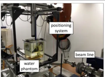
The calorimeter was positioned at a distance of 0.9 m from the beam exit window of the accelerator (Figure 3). The pencil electron beam was broadened by a double scattering foil system consisting of the copper foil of the vacuum exit window and a 1 mm thick disk of aluminum positioned 3.5 cm away on the beam central axis. A 10 × 10 cm standard clinical electron applicator from an Elekta Precise linear accelerator was used in order to generate a square radiation field with an approximately parabolic radial profile within the center portion. The radiation field was shaped to be similar to that from a previous experiment with this calorimeter [44], so that the existing simulations for field perturbation and beam non-uniformity correction factors were suitable.
FIGURE 3 | Calorimeter in front of the beamline of PTB’s research linear accelerator. The calorimeter is on the left, enclosed in blue polystyrene, the end of the beam line is on the right.
The electron energy used for the investigation of the response of the calorimeter was 50 MeV. The choice of energy is somewhat arbitrary for the investigation where the focus is varying the DPP, but a very high energy provides a flatter depth-dose curve and therefore a more uniform temperature environment for the calorimeter core. For the measurements in the ultra-high DPP range 10 beam pulses were delivered within 2 s to the calorimeter while the charge of each beam pulse was measured simultaneously with the ICT. The pulse charge, and thus the DPP, was varied between 5 and 45 nC per pulse (0.3–1.8 Gy per pulse). The measurement was repeated five times for each pulse charge setting.
RESULTS
Dose Per Beam Pulse Charge From
Alanine Measurements
The radiation field from the research accelerator is not flat, as is typical for a clinical linear accelerator, and without any electron dual scattering foil systems [46,47] for electron beam flattening (as used in the second experiment with the calorimeter) the radiation field shows a Gaussian shape (Figure 4). There is good agreement between the relative lateral ionization measurement with the Advanced Markus ionization chamber and the alanine measurements at different DPP. Both detectors average over a comparable range of the dose gradient (alanine 3 mm, ionization chamber 5 mm). For the determination of the absolute dose at the central beam axis (the position of the ionization chamber during the kSdetermination) a 2nd order polynomial function was fitted
to the alanine datapoints and the maximum at lateral position 0 was taken.
Figure 5 shows the dose per beam pulse (gray squares)
determined this way as a function of the charge per beam pulse measured simultaneously by means of the ICT. The linear fit of the alanine data is used as the calibration function for the determination of the actual DPP at the position of the sensitive
FIGURE 4 | Absolute absorbed dose (right y-axis) as measured by stacks of eight alanine pellets for different beam pulse charges and thus different DPP. The corresponding lines are best fits of a 2nd order polynomial function. Also shown is a relative ionization measurement (only left y-axis) with the ionization chamber at low DPP in the same water depth with a Gaussian fit.
FIGURE 5 | Dose per pulse Dref
w,pulsedetermined by means of PTB’s alanine
dosimetry system (gray squares) as a function of the measured charge per beam pulse. Also shown are measurements with an Advanced Markus ionization chamber at a 300 V operating voltage without taking into account any ion recombination correction factor kSat the same position and conditions
as the alanine (blue dots). The dashed line represents the fit function to measurements by Petersson et al. [13].
volume of the Advanced Markus ionization chamber from the measured beam pulse charge.
Ion Recombination Correction for the
Advanced Markus Chamber
The blue dots in Figure 5 show the dose per beam pulse measured with the Advanced Markus ionization chamber at a 300 V operating voltage without taking into account any ion recombination correction factor DICw,pulse/kSas a function of the
Bourgouin et al. Calorimeter for Real-Time FLASH Dosimetry
FIGURE 6 | Typical calorimeter temperature-time trace from 10 radiation pulses of about 1 Gy/pulse. The data acquisition rate is 1 Hz.
reference Drefw,pulsemeasured by means of the ICT calibrated with alanine increases with the increasing charge per pulse/increasing dose per pulse. The blue dashed line represents the fit function given in Ref. [13] by Petersson et al. for experimentally determined kS values for the Advanced Markus chamber at
300 V from, among others, comparison with radiochromic film measurements. This function is kS=(1 + (Drefw,pulse/300)
2.5
)0.144, where Drefw,pulseis expressed in mGy.
At 1.5 Gy/pulse (as applied for the first treatment of a human with FLASH radiotherapy) the ion recombination correction amounts to 79%. The measurement uncertainty is therefore dominated by the uncertainty of the kS factor and thus an
uncertainty of the dose measurement comparable to those reached at conventional radiation therapy (< 2%), seems not possible with this ionization chamber type.
Calorimeter Measurements
A typical calorimeter temperature-trace recorded in this work is shown in Figure 6. The radiation-induced temperature rise, 1T, is obtained by linearly extrapolating the pre- and post-irradiation traces to the center of the irradiation time as illustrated. The difference in the gradient of the pre- and post-irradiation traces is due to the relatively poor thermal isolation of the calorimeter, but this does not have a large effect on the accuracy of the results since the irradiation time is relative short compared to the heat transfer time constant. The good signal-to-noise ratio indicates that the calorimeter is sensitive enough to also measure a single pulse at ultra-high DPP. For a series of irradiations, the standard deviation of the temperature rise, normalized to the delivered beam charge, was typically 0.1%, comparable with primary standard calorimeters in electron beams (e.g., [48]).
There are variations in the post-irradiation gradient. These are random with respect to the DPP and therefore likely due to external environmental factors. The heat loss is significantly
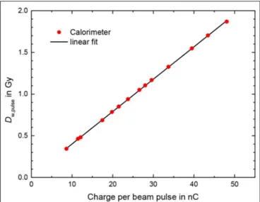
FIGURE 7 | Dose per pulse from calorimeter measurements Dcalo w,pulse
according to Equation 1 using an conversion factor from dose to aluminum in dose to water of 1.23 as a function of the charge per beam pulse measured by the ICT. Line: linear fit.
larger than for a water calorimeter, primarily due to the high thermal conductivity of the aluminum and the simple thermal isolation of the calorimeter core. However, the time constant for the heat loss is an order of magnitude larger than the irradiation time and therefore the calorimeter can be considered to be operating in a quasi-adiabatic mode. The heat loss correction, kht, is therefore small (< 0.5%) and does not impact the overall
uncertainty in the calorimeter dose determination.
The results for the calorimeter measurements (Figure 7), for measurements carried out on two different days, show that there is good repeatability between the two sets of measurements and that there is a linear relationship between the calorimeter dose and beam pulse.
The deviation of the calorimeter response from the linear fit function shown in Figure 7 was generally smaller than 0.5% (Figure 8). The bars in Figure 8 for the calorimeter represent only type A standard uncertainty for a sequence of 5 measurements in close succession with the same conditions and are therefore a measure of the short-term repeatability, not the actual uncertainty. The mean charge of the 10 delivered pulses are measured with absolute uncertainty of +/-0.005 nC, thus for the used pulse charges of more than 10 nC the uncertainty contribution is smaller than 0.05%. The uncertainty of the charge measurement is therefore probably not the main reason for the fluctuation of the values.
The deviations of the alanine dose measurements from the ICT calibration function shown in Figure 5, used as reference for the experiment with the ionization chamber, reveals a good linearity as well (squares in Figure 8). The corresponding bars in Figure 8 represent the statistical uncertainty contributions (k = 1) due to the variation in the homogeneity and mass as well as in the measured ESR signal of the alanine test pellets resulting in a relative uncertainty of 0.2% of the total dose measured with
FIGURE 8 | Deviation of the calorimeter response from the linear fit function shown in Figure 7 as a function of the dose per pulse. The bars represent only type A standard uncertainty for a sequence of 5 measurements and do not represent the actual uncertainty. Also shown is the deviations of the alanine dose measurements from the ICT calibration function show in Figure 5. The bars represent the statistical uncertainty contributions (k = 1, see text).
eight pellets. The absolute uncertainties for the delivered total doses (about 14 Gy) are ∼30 mGy. The absolute uncertainty of the DPP increases with the DPP, since at low DPP about 500 beam pulses are needed to deliver 14 Gy while at the highest DPP only 6 pulses were irradiated to reach the same dose level. In the studied DPP range the deviation from the linear behavior is smaller than 0.5%. Good linearity was expected since the ICT signal was found to be linear with the pulse charge [34], the dose is proportional to the number of irradiated electrons and alanine is known to be independent of dose rate [19]. The data in Figure 8 indicate that the linearity of the calorimeter is comparable with the alanine dosimetry system.
DISCUSSION
There is very good agreement between the ion recombination correction kS of the Advanced Markus chamber determined
by Petersson et al. [13] and in this work (Figure 5). However, Petersson et al. had examined three different specimens of an Advanced Markus chamber and observed a noticeable spread in the kSvalues between the specimens (e.g., up to 3.2% deviation
from the mean value at 2.5 Gy/pulse). Therefore, the remarkably good agreement of the specimen examined here with the mean value of the three specimens examined by Petersson et al. does not allow for a conclusion about the universality of the kSfunction for
all specimens of this chamber type.
The initial measurements with the calorimeter described above suggest that such a calorimeter could be a suitable real-time detector for the accurate dosimetry of ultra-high DPP beams. The simple aluminum calorimeter used provides sufficient precision for clinical radiation dosimetry measurements and approaches
that of primary standard electron beam calorimeters [48, 49]. The simplicity of the calorimeter design means that it could potentially be used in a clinical setting to directly determine the absorbed dose to water. However, for such an application there are three additional requirements, the first being the determination of the conversion factor from aluminum to water. This has been done for graphite using Monte Carlo radiation transport simulations (e.g., [44]) and therefore should be straightforward for this similar design. An achievable overall standard uncertainty in the determination of absorbed dose to water using this calorimeter design is 0.5%. The second requirement is that the thermal isolation is sufficient for a clinical setting. The irradiation area at PTB’s research linear accelerator is carefully temperature controlled, to provide a stable background against which the radiation-induced temperature rise can be measured, but this might not be the case for a radiation therapy linac bunker. It may be that some form of additional temperature control will be required and then a design such as that developed by McEwen and Duane [50] could be used. The third requirement is a full validation of the calorimeter as an absorbed dose standard. This would include long-term stability testing, confirmation of the absence of an accumulated-dose dependence, measurements in a range of electron beams, and a comparison with existing dosimetry standards.
The very short irradiation times of FLASH radiotherapy, which makes this calorimeter design very suitable, also means that other operating modes of ionizing radiation calorimeters cannot be used. For example, the isothermal mode extensively used by the Laboratoire National Henri Becquerel (LNHB) [51] uses electrical heating to maintain a constant (elevated) temperature of the calorimeter and adjusts the electrical power dissipation to compensate for the energy deposited by the radiation beam. It has been shown that this mode can provide lower Type A uncertainties (< 0.1%) but the time constant of the isothermal control systems is not fast enough to work within such short irradiation times.
The aluminum calorimeter used here can be optimized further. The current geometry is suitable for standard large fields (10 × 10 cm) but a smaller core or cylindrical, rather than plane-parallel geometry, may be better. A design such as that developed by Renaud et al. [52] would be worth investigating as this could be used in small IMRT fields (3 × 3 cm or smaller) for both photon and electron beams. Aluminum may not be suitable for all beam modalities (e.g., kV x-rays, protons, heavy ions) but even in these situations, the linearity of the calorimeter is unaffected, and it could therefore still be useful as a transfer detector for another dosimeter. In addition to geometric modifications, there is the potential to simplify the data acquisition system, given the high signal-to-noise obtained for these high DPP values. Replacing the multi-component AC-bridge read-out with a high-accuracy digital multimeter should still yield a suitable signal and offer a more routine operation in a clinical setting. As shown in Figure 8, one can argue that the calorimeter out-performs alanine, in terms of precision, linearity, and immediacy and therefore an optimized calorimeter design could be the default detector for clinical FLASH beams, rather than being used to validate other detector systems.
Bourgouin et al. Calorimeter for Real-Time FLASH Dosimetry
CONCLUSION
Three detector systems were investigated for the accurate dosimetry of electron beams with ultra-high DPP. Measurements were carried out in high-energy electron beams of a research linear accelerator, in a DPP range of at least 0.3–1.8 Gy/per pulse, i.e., around 1.5 Gy/pulse as applied for the treatment with FLASH radiotherapy. Passive alanine dosimeters were shown to have a linear response with the DPP up to at least 2.4 Gy/pulse, but there is no real-time read-out. The alanine system was used, however, as reference to determine the ion recombination correction for an Advanced Markus plane-parallel ionization chamber, studied as a possible real-time dose monitor at ultra-high DPP. The correction was found to be 79% at 1.5 Gy/pulse, consistent with previously reported results using radiochromic film as a reference. Therefore, ionization chambers used for dosimetry in conventional radiation therapy are not considered suitable for accurate dosimetry in FLASH radiation therapy. Finally, an aluminum open-to-atmosphere calorimeter, operating in the quasi-adiabatic mode, was investigated as an alternative real-time dosimeter for FLASH radiotherapy. The precision of the calorimeter was estimated to be < 0.2% and the response of the calorimeter was found to be proportional to the dose per pulse in the investigated range of 0.3 to 1.8 Gy/pulse with an average deviation from the linear fit compared to the pulse charge being < 0.5%. This linearity was consistent with that determined for alanine, confirming the suitability of a simplified calorimeter design that could be used for real-time dosimetry of clinical FLASH therapy radiation beams.
DATA AVAILABILITY STATEMENT
The raw data supporting the conclusions of this article will be made available by the authors, without undue reservation.
AUTHOR CONTRIBUTIONS
AB co-developed the calorimeter, performed, and evaluated the calorimeter measurements. AS carried out the irradiation of the calorimeter, the alanine probes, and the ionization chamber. TH performed and evaluated the alanine measurements. RK and DP performed and evaluated the measurements with the ionization chamber. MM and R-PK developed the research plan and oversaw the research. All authors contributed to the article and approved the submitted version.
FUNDING
This project has received funding from the EMPIR program co-financed by the Participating States and from the European Union’s Horizon 2020 research and innovation program.
ACKNOWLEDGMENTS
We thank Christoph Makowski for the operation of the electron accelerator. The assistance of Markus Meier in the preparation of the experiments is gratefully acknowledged.
REFERENCES
1. Favaudon V, Caplier L, Monceau V, Pouzoulet F, Sayarath M, Fouillade C, et al. Ultrahigh dose-rate FLASH irradiation increases the differential response between normal and tumor tissue in mice. Sci Trans Med. (2014) 6:245. doi: 10.1126/scitranslmed.3008973
2. Montay-Gruel P, Bouchet A, Jaccard M, Patin D, Serduc R, Aim W, et al. X-rays can trigger the FLASH effect: Ultra-high dose-rate synchrotron light source prevents normal brain injury after whole brain irradiation in mice. Radiother Oncol. (2018) 129:582–8. doi: 10.1016/j.radonc.2018.08.016 3. Montay-Gruel P, Acharya MM, Petersson K, Alikhani L, Yakkala C, Allen
BD, et al. Long-term neurocognitive benefits of FLASH radiotherapy driven by reduced reactive oxygen species. Proc Natl Acad Sci USA. (2019)
166:10943–51. doi: 10.1073/pnas.1901777116
4. Bourhis J, Sozzi WJ, Jorge PG, Gaide O, Bailat C, Duclos F, et al. Treatment of a first patient with FLASH-radiotherapy. Radiother Oncol. (2019) 139:18–22. doi: 10.1016/j.radonc.2019.06.019
5. Bourhis J, Montay-Gruel P, Gonçalves Jorge P, Bailat C, Petit B, Ollivier J, et al. Clinical translation of FLASH radiotherapy: Why and how? In Radiother Oncol. (2019) 139:11–7. doi: 10.1016/j.radonc.2019.04.008
6. Wilson JD, Hammond EM, Higgins GS, Petersson K. Ultra-High Dose Rate (FLASH) radiotherapy: silver bullet or fool’s gold? Front Oncol. (2020) 9:1563. doi: 10.3389/fonc.2019.01563
7. Jaccard M, Durán MT, Petersson K, Germond JF, Liger P, et al. High dose-per-pulse electron beam dosimetry: commissioning of the Oriatron eRT6 prototype linear accelerator for preclinical use. Med Phys. (2018)
45:863–74. doi: 10.1002/mp.12713
8. Favaudon V, Lentz JM, Heinrich S, Patriarca A, de Marzi L, Fouillade C, et al. Time-resolved dosimetry of pulsed electron beams in very high dose-rate, FLASH irradiation for radiotherapy preclinical studies. Nucl Instrum Methods Phys Res B. (2019) 944:162537. doi: 10.1016/j.nima.2019.162537
9. Schüler E, Trovati S, King G, Lartey F, Rafat M, Villegas M, et al. Experimental platform for ultra-high dose rate FLASH irradiation of small animals using a clinical linear Accelerator. Int J Rad Oncol Biol Phys. (2017) 97:195–203. doi: 10.1016/j.ijrobp.2016.09.018
10. Lempart M, Blad B, Adrian G, Bäck S, Knöös T, Ceberg C, et al. Modifying a clinical linear accelerator for delivery of ultra-high dose rate irradiation. Radiother Oncol. (2019) 139:40–5. doi: 10.1016/j.radonc.2019.01.031 11. Maxim PG, Tantawi SG, Loo BW. PHASER: a platform for clinical translation
of FLASH cancer radiotherapy. Radiother Oncol. (2019) 139:28–33. doi: 10.1016/j.radonc.2019.05.005
12. Diffenderfer ES, Verginadis II, Kim MM, Shoniyozov K, Velalopoulou A, Goia D, et al. Design, implementation, and in vivo validation of a novel proton FLASH radiation therapy system. Int J Rad Oncol Biol Phys. (2020) 106:440–8. doi: 10.1016/j.ijrobp.2019.10.049
13. Petersson K, Jaccard M, Germond, J.-F., Buchillier T, Bochud F, et al. High dose-per-pulse electron beam dosimetry - a model to correct for the ion recombination in the Advanced Markus ionization chamber. Med Phys. (2017) 44:1157–67. doi: 10.1002/mp.12111
14. Lansonneur P, Favaudon V, Heinrich S, Fouillade C, Verrelle P, De Marzi L. Simulation and experimental validation of a prototype electron beam linear accelerator for preclinical studies. Phys Med. (2019) 60:50–7. doi: 10.1016/j.ejmp.2019.03.016
15. Palmans H, Andreo P, Huq MS, Seuntjens J, Christaki KE, Meghzifene A. Dosimetry of small static fields used in external photon beam radiotherapy: Summary of TRS-483, the IAEA–AAPM international Code of Practice for reference and relative dose determination. Med Phys. (2018) 45:e1123–45. doi: 10.1002/mp.13208
16. Jaccard M, Petersson K, Buchillier T, Germond, JF, Durán MT, et al. High dose-per-pulse electron beam dosimetry: Usability and dose-rate independence of EBT3 Gafchromic films. Med Phys. (2017) 44:725–35. doi: 10.1002/mp. 12066
17. Jorge PG, Jaccard M, Petersson K, Gondré M, Durán MT, Desorgher L, et al. Dosimetric and preparation procedures for irradiating biological models with pulsed electron beam at ultra-high dose-rate. Radiother Oncol. (2019)
139:34–9. doi: 10.1016/j.radonc.2019.05.004
18. Gondré M, Jorge PG, Vozenin, M.-C., Bourhis J, Bochud F, et al. Optimization of alanine measurements for fast and accurate dosimetry in FLASH radiation therapy. Rad Res. (2020). doi: 10.1667/rr15568.1
19. ISO (2004). International Organization for Standardization. Practice for Use of the Alanine-EPR Dosimetry System. ISO/ASTM Standard 51607. (Geneva: ISO). Available online at: https://www.iso.org/standard/39026.html 20. Regulla DF, Deffner U. A system of transfer dosimetry in radiation processing.
Radiat Phys Chem. (1983) 22:305–9. doi: 10.1016/0146-5724(83)90034-1 21. Kudoh H, Celina M, Kaye RJ, Gillen KT, Clough RL. Response of alanine
dosimeters at very high dose rate. Appl Radiat Isot. (1997) 48:497–9. doi: 10.1016/S0969-8043(96)00281-3
22. Bruggmoser G, Saum R, Schmachtenberg A, Schmid F, Schüle E. Determination of the recombination correction factor kS for some specific plane-parallel and cylindrical ionization chambers in pulsed photon and electron beams. Phys Med Biol. (2007) 52:35–50. doi: 10.1088/0031-9155/52/2/N01
23. Di Martino F, Giannelli M, Traino AC, Lazzeri M. Ion recombination correction for very high dose-per-pulse high-energy electron beams. Med Phys. (2005) 32:2204–10. doi: 10.1118/1.1940167
24. Laitano RF, Guerra AS, Pimpinella M, Caporali C, Petrucci A. Charge collection efficiency in ionization chambers exposed to electron beams with high dose per pulse. Phys Med Biol. (2006) 51:6419–36. doi: 10.1088/0031-9155/51/24/009
25. Scalchi P, Ciccotelli A, Felici G, Petrucci A, Massafra R, Piazzi V, et al. Use of parallel-plate ionization chambers in reference dosimetry of NOVAC and LIAC R mobile electron linear accelerators for intraoperative radiotherapy: a multi-center survey. Med Phys. (2017) 44:321–32. doi: 10.1002/mp.12020 26. Pimpinella M, Andreoli S, De Angelis C, Della Monaca S, D’Arienzo M,
Menegotti L. Output factor measurement in high dose-per-pulse IORT electron beams. Phys Med. (2019) 61:94–102. doi: 10.1016/j.ejmp.2019.04.021 27. D’Arienzo M, Andreoli S, Pimpinella M. Evaluation of the uncertainty associated with the ion recombination correction in high dose-per-pulse electron beam dosimetry: an MC approach. Phys Med Biol. (2020) 65:09NT01. doi: 10.1088/1361-6560/ab79c2
28. Almond PR, Biggs PJ, Coursey BM, Hanson WF, Huq MS, Nath R, et al. AAPM’s TG-51 protocol for clinical reference dosimetry of high-energy photon and electron beams. Med Phys. (1999) 26:1847–70.
29. International Atomic Energy Agency. Absorbed Dose Determination in External Beam Radiotherapy: An International Code of Practice for Dosimetry Based on standards of Absorbed Dose to Water. Tech Rep TRS-398. Vienna: IAEA (2000).
30. DIN 6800-2:2008-03. Procedures of dosimetry with probe type detectors for photon and electron radiation - Part 2: Ionization chamber dosimetry of high energy photon and electron radiation. Acta Radiol Oncol. (1980) 19:55–79. doi: 10.31030/1409685
31. Boag JW, Hochhäuser E, Balk OA. The effect of free-electron collection on the recombination correction to ionization measurements of pulsed radiation. Phys Med Biol. (1996) 41:885–97. doi: 10.1088/0031-9155/41/5/005 32. McManus M, Romano F, Lee ND, Farabolini W, Gilardi A, Royle G,
et al. The challenge of ionisation chamber dosimetry in ultra-short pulsed high dose-rate very high energy electron beams. Sci Rep. (2020) 10:9089. doi: 10.1038/s41598-020-65819-y
33. Schüller A, Pojtinger S, Meier M, Makowski C, Kapsch RP. The metrological electron accelerator facility (MELAF) for research in dosimetry for radiotherapy. In: IFMBE Proceedings. Vol. 68.589–93 Springer Verlag (2019). doi: 10.1007/978-981-10-9023-3_109
34. Schüller A, Illemann J, Renner F, Makowski C, Kapsch RP. Traceable charge measurement of the pulses of a 27 MeV electron beam from a linear accelerator. J Instrum. (2017) 12:P03003. doi: 10.1088/1748-0221/12/03/P03003
35. Krauss A. The PTB water calorimeter for the absolute determination of absorbed dose to water in 60Co radiation. Metrologia. (2006) 43:259–72. doi: 10.1088/0026-1394/43/3/008
36. Anton M. Uncertainties in alanine/ESR dosimetry at the physikalisch-technische bundesanstalt. Phys Med Biol. (2006) 51:5419–40. doi: 10.1088/0031-9155/51/21/003
37. Anton M, Kapsch RP, Krauss A, Von Voigts-Rhetz P, Zink K, McEwen M. Difference in the relative response of the alanine dosimeter to megavoltage x-ray and electron beams. Phys Med Biol. (2013) 58:3259–82. doi: 10.1088/0031-9155/58/10/3259
38. Vörös S, Anton M, Boillat B. Relative response of alanine dosemeters for high-energy electrons determined using a fricke primary standard. Phys Med Biol. (2012) 57:1413–32. doi: 10.1088/0031-9155/57/5/1413
39. McEwen M, Miller A, Pazos I, Sharpe P. Determination of a consensus scaling factor to convert a Co-60-based alanine dose reading to yield the dose delivered in a high energy electron beam. Radiat Phys Chem. (2020)
171:108673. doi: 10.1016/j.radphyschem.2019.108673
40. Renaud J, Palmans H, Sarfehnia A, Seuntjens J. Absorbed dose calorimetry. Phys Med Biol. (2020) 65:05TR02. doi: 10.1088/1361-6560/ab4f29
41. Miller A, Kovas A. Application of calorimeters for routine and reference dosimetry at 4-10 MeV industrial electron accelerators. Int J Radiat Appl Instrumentation. (1990) 35:774–8. doi: 10.1016/1359-0197(90) 90314-8
42. Burns D T, McEwen M, Williams A J. An NPL absorbed dose calibration service for electron beam radiotherapy. In: SP Flitton, editor. Proc. Int. Symp. on Measurement Assurance in Dosimetry. Vienna: IAEA (1994). p. 61.
43. Ross CK, Seuntjens J, Klassen N, Shortt K. The NRC sealed water calorimeter: correction factors and performance. In: Proceedings of the Workshop on Recent Advances in Calorimetric Absorbed Dose Standards. Teddington: National Physical Laboratory (2000).
44. Bourgouin A, Cojocaru C, Ross C, McEwen M. Determination of Wair in high-energy electron beams using graphite detectors. Med Phys. (2019)
46:5195–208. doi: 10.1002/mp.13772
45. Nutbrown RF, Duane S, Shipley DR, Thomas RAS. Evaluation of factors to convert absorbed dose calibrations from graphite to water for the NPL high-energy photon calibration service. Phys Med Biol. (2002) 47:441–54. doi: 10.1088/0031-9155/47/3/306
46. Grusell E, Montelius A, Brahme A, Rikner G, Russell K. A general solution to charged particle beam flattening using an optimized dual-scattering-foil technique, with application to proton therapy beams. Phys Med Biol. (1994)
39:2201–16. doi: 10.1088/0031-9155/39/12/005
47. Carver RL, Hogstrom KR, Price MJ, LeBlanc JD, Pitcher GM. Real-time simulator for designing electron dual scattering foil systems. J Appl Clin Med Phys. (2014) 15:323–42. doi: 10.1120/jacmp.v15i6.4849
48. Krauss A, Kapsch RP. Direct determination of k Q factors for cylindrical and plane-parallel ionization chambers in high-energy electron beams from 6 MeV to 20 MeV. Phys Med Biol. (2018) 63:035041. doi: 10.1088/1361-6560/aaa71e
49. McEwen MR, DuSautoy AR, Williams AJ. The calibration of therapy level electron beam ionization chambers in terms of absorbed dose to water. Phys Med Biol. (1998) 43:2503–19.
50. McEwen MR, Duane S. A portable calorimeter for measuring absorbed dose in the radiotherapy clinic. Phys Med Biol. (2000) 45:3675–91. doi: 10.1088/0031-9155/45/12/312
51. Daures J, Ostrowsky A. New constant-temperature operating mode for graphite calorimeter at LNE-LNHB. Phys Med Biol. (2005) 50:4035–52. doi: 10.1088/0031-9155/50/17/008
52. Renaud J, Sarfehnia A, Bancheri J, Seuntjens J. Aerrow: a probe-format graphite calorimeter for absolute dosimetry of high-energy photon beams in the clinical environment. Med Phys. (2018) 45:414–28. doi: 10.1002/mp. 12669
Conflict of Interest:RK and DP are employees of PTW Freiburg.
The remaining authors declare that the research was conducted in the absence of any commercial or financial relationships that could be construed as a potential conflict of interest.
Copyright © 2020 Bourgouin, Schüller, Hackel, Kranzer, Poppinga, Kapsch and McEwen. This is an open-access article distributed under the terms of the Creative Commons Attribution License (CC BY). The use, distribution or reproduction in other forums is permitted, provided the original author(s) and the copyright owner(s) are credited and that the original publication in this journal is cited, in accordance with accepted academic practice. No use, distribution or reproduction is permitted which does not comply with these terms.