N x
/
An Analysis of Noise Reduction in Variable
Reluctance Motors Using
Pulse Position Randomization
byMelissa C. Smoot
B.S. Elec. Eng. and Comp. Sci., Princeton University (1982) Submitted to the Department of Ocean Engineering
and the Department of Electrical Engineering and Computer Science in partial fulfillment of the requirements for the degrees of
Naval Engineer
Master of Science in Electrical Engineering and Computer Science at the
MASSACHUSETTS INSTITUTE OF TECHNOLOGY
May, 1994 "he author hereby gants to MIT
penTsslOn to reproduce and to (Melissa C. Smoot, 1994. All rights reserved. dstribute publicly paper and
electronic copies of ts thesis
document in whole or In part.
Author . . ... .
Department of Ocean Engineering
/ X I / , May 13, 1994
Certified by
. . ..
.. ....-" / CJohn G. Kassakian
Professor of Electrical Engineering Thesis Supervisor
Certified by ....
...
c; -· - ~~~ ~~''''''A:A. Douglas Carmichael Professor of Power Engineering
r1~~
Amp-~
I~
~ Thesis Reader
Accepted
by
...
-vDouglas Carmlchael Chairman, Committee on Graduate Students
\
1, 1'1
j n. .--- ' ent of Ocean EngineeringAccepted
by
. r
... ...
-F. R. Morgenthaler
Chairman,
Committee on Graduate Students iffbi~tine'/it of Electrical Engineering and Computer ScienceAn Analysis of Noise Reduction in
Variable Reluctance Motors Using
Pulse Position Randomization
by
Melissa C. Smoot
Submitted to the Department of Ocean Engineering and the Department of Electrical
Engineering and Computer Science on May 13, 1994 in partial fulfillment of the
requirements for the Degrees of Naval Engineer and Master of Science in Electrical Engineering and Computer Science
Abstract
The design and implementation of a control system to introduce randomization into the control of a variable reluctance motor (VRM) is presented. The goal is to
reduce noise generated by radial vibrations of the stator. Motor phase commutation
angles are dithered by 1 or 2 mechanical degrees to investigate the effect of randomization on acoustic noise. VRM commutation points are varied using a
uniform probability density function and a 4 state Markov chain among other methods.
The theory of VRM and inverter operation and a derivation of the major source of
acoustic noise are developed.
The experimental results show the effects of randomization. Uniform dithering and Markov chain dithering both tend to spread the noise spectrum, reducing peak
noise components. No clear evidence is found to determine which is the optimum
randomization scheme. The benefit of commutation angle randomization in reducing
VRM loudness as perceived by humans is found to be questionable.
Thesis Supervisor: Dr. John G. Kassakian
ACKNOWLEDGEMENTS
I would first like to thank my thesis supervisor, Prof. John Kassakian, for his patience and support (and Tuesday night pizzas). His wonderful power electronics course motivated my interest in the field, and my work on this thesis with him served to heighten that interest.
This thesis would not have come to fruition without Dave Perreault, my
guardian angel throughout this work. He consistently provided the technical expertise I needed to get over the rough spots, voluntarily spending many hours helping me
troubleshoot when things looked grim at the eleventh hour. It was his suggestion to
pursue this topic in the first place.
Prof. Alex Stankovi6 of Northeastern Univ. was also invaluable. His Ph.D. provided the impetus for the randomization, and his knowledge of the subject and suggestions helped me design the control system.
Other LEES lab people contributed in smaller ways, including the Friday trips
to the 'Ear. Tracy Clark solved the circuit noise problems, and the motor finally
turned. Kamakshi Srinivasan consistently took the time to answer my endless stream of questions. Karen Walrath provided the data acquisition equipment. Many other
people in the lab helped me along the way: Mary Tolikas, Deron Jackson, Jeff
Chapman, Brian Eidson ... the list includes most people in the lab, because people
always seemed to have time to help.
Most of all I thank my parents, Bill and Jane Smoot, for their love, support and constant encouragement throughout my sojourn at MIT. A special thanks goes to my father for his insightful proofreading and editorial suggestions which made the final writing much smoother.
TABLE OF CONTENTS
INTRODUCTION
...
1.1 Background ... . . . 9
1.2 Thesis Outline .
VRM AND INVERTER OPERATION ... 2.1 VRM Construction ... 2.2 VRM Principles of Operation ... 2.2.1 VRM Dynamics ... 2.2.2 VRM Practical Considerations ... 2.3 VRM Inverter Operation ... 2.3.1 Normal Operation ... .. ... 2.3.2 Regenerative Operation ... 2.4 VRM Acoustic Noise ... 2.4.1 VRM Noise Sources ...
2.4.2 Inverter Drive Contributions to
. VRM
VRM
Acoustic. . . . .
Acoustic
Noise ...
CONTROLLER OPERATION ...3.1 Optical Shaft Encoder ...
3.2 Motorola 68332 Microcontroller Unit (MCU) 3.2.1 Time Processor Unit Operation .... 3.2.2 Software Development ... 9 12 14 14 16 16 19 21 22 23 25 25 27 32 33 36 36 39 . . .
...
...
...
3.3 Controller Hardware ... 3.3.1 MCU Interface Board ... 3.3.2 Inverter Controller Board ... 3.3.3 Inverter Board ... 3.4 Fault Tolerance ...
RANDOMIZATION SCHEMES ... 4.1 Commutation Points ...
4.1.1 Nominal Timing Between Phases ... 4.1.2 Nominal ON and OFF Points ... 4.2 Randomization Terminology ...
4.2.1 W aveform Description ... 4.2.2 Categories of Randomization ... 4.3 Experimental Randomization Schemes ... 4.3.1 Random Number Generation ...
4.3.2 Selection and Application of Randomization Schemes ... EXPERIMENTAL RESULTS ...
5.1 Experimental Setup ...
5.1.1 Acoustic Noise Measurement ... 5.1.2 Speed Measurements ... 5.1.3 Other Measurements ... 5.2 Comparing Randomization Schemes ... 5.3 The Experimental Randomization Schemes
5.3.1 Stationary Randomization Schemes
DITH6)
...
64 (DITH1, DITH2, DITH3, and
5.3.2 Non-Stationary Randomization Schemes (DITH4, DITH5) ... 5.4 Results ... 5.4.1 Trials ... 5.4.2 Spectral Plots ... 5.4.3 Experimental Limitations ....
CONCLUSIONS
...
64 65 65 67 68 76 77 40 40 40 42 43 45 45 45 47 49 49 51 53 54 55 58 58 59 61 62 63 . .. ....
...
...
...
...
...
...
...
6.1 Lessons Learned ... 78
6.2 Suggestions for Future Research ... 78
REFERENCES ... 80
APPENDIX A: Schematic Diagrams ... 83
LIST OF FIGURES
Figure 2.1 End view of the geometry of the 8/6 VRM. An example winding
is shown ... .... 15
Figure 2.2 Idealized variation of phase inductance with rotor position ... 19
Figure 2.3 Rotor position and inductance of the four phases ... 20
Figure 2.4 Simplified circuit for a single phase of the VRM inverter ... 21
Figure 2.5 2D and 3D view of closed surface for calculating forces on the stator . 25 Figure 2.6 Stator vibration modes. (a) Single ovalization of the stator. (b) Double 28 ovalization of the stator. (c) Breathing mode of the stator. Figure 2.7 (a) Plot of current vs. time (position) during the time a phase is ... 29
energized. (b) Plot of inductance vs. time during the same period. Figure 3.1 Block diagram of the VRM laboratory setup including inverter, ... 33
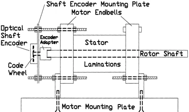
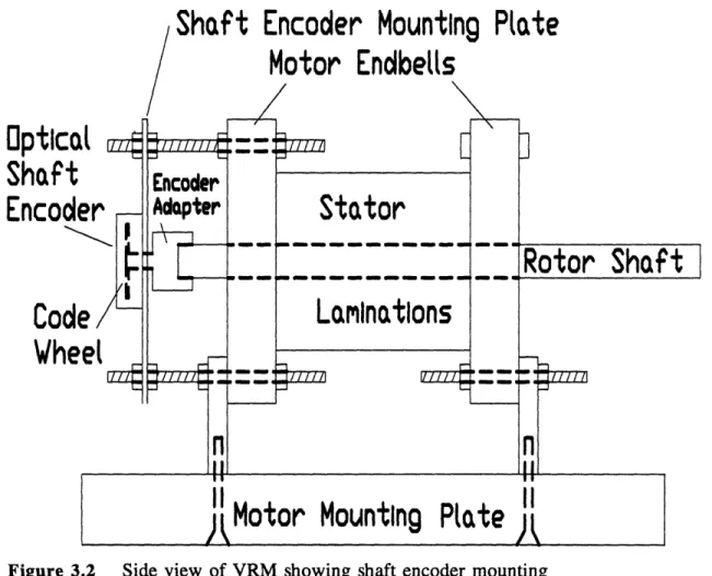
control system and user interface. Figure 3.2 Side view of VRM showing shaft encoder mounting ... 35
Figure 4.1 Nominal timing relationship between the control signals for the .... 46
four phases. Figure 4.2 Classification of basic random switching terminology ... 50
Figure 4.3 Four state Markov chain used in the experiments. Numbers ... 54 represent the assigned probabilities for all possible state
Figure 5.1 Block diagram of the laboratory setup, showing the VRM and ... 59 load, control system components, and measuring equipment.
Figure 5.2 Sound meter average output voltage correlation to sound ... 66 meter analog dB level.
Figure 5.3 Raw data and spectral analysis, equal angle trials, dc supply = 30V, 67
chop current = 1.96A, 2700 rpm, scheme DITHO no dither.
Figure 5.4 Raw data and spectral analysis, equal angle trials, dc supply = 30V, . 69
chop current = 1.96A, 2700 rpm, scheme DITHO no dither.
Figure 5.5 Comparison between equal angle trials, scheme DITH2 with 1 degree . 70 and 2 degrees of OFF dither.
Figure 5.6 Comparison between equal angle trials, scheme DITH4 with 1 degree . 71
and 2 degrees of OFF dither.
Figure 5.7 Comparison between equal angle trials, scheme DITH5 with 1 degree . 72 and 2 degrees of OFF dither.
Figure 5.8 Comparison between equal angle trials, scheme DITH6 with 1 degree . 73
and 2 degrees of OFF dither.
Figure 5.9 Comparison between initial trials without equal angles and before ... 74 optimizing, DITHO no dither and DITH1 with 1 degree of ON dither. Figure 5.10 Comparison between initial trials without equal angles and before ... 75
optimizing, DITHO no dither and DITH3 with 1 degree of ON/OFF dither.
Chapter
1
INTRODUCTION
The variable reluctance motor (VRM) is a versatile motor that has relatively
few applications today. Its major disadvantage is that it is acoustically noisy, to the
point where humans often require hearing protection in the vicinity of an operating VRM. This discomfort and potential for damage to an unprotected person's hearing
have severely limited the use of VRM's. This thesis explores the use of different
randomization schemes on VRM switching to reduce acoustic noise from VRM's. 1.1 Background
The VRM has many advantages over other types of motors. The most obvious advantage is its simpler construction, and thus lower cost. Dc motors and ac
synchronous motors require windings on the rotor, along with a commutator or slip rings. The induction motor has either windings or conducting bars on the rotor. The VRM rotor simply consists of iron laminations, without windings or bars. Thus, the VRM rotor is the most robust rotor available. In addition to the rotor, the stator of a
doubly salient VRM is relatively easy to construct, since the phase windings can be
have salient poles. This arrangement produces the highest torque per frame size in
VRM's.[1, 2]
The VRM has other advantages over induction motors (IM), the most widely used motors today. Moghbelli conducted an analysis of VRM and IM attributes, using 10 hp motors, and found that the VRM compared favorably[l]. The most notable VRM attribute was efficiency; VRM efficiency was found to be relatively constant for 75-100% of rated load, and generally higher than IM efficiency which varied with load. Thus, the VRM produced torque efficiently and economically at various speeds
and loads. In addition, the VRM can give constant power over a range of speeds,
which makes it very good for traction applications[3].
The major disadvantage of the VRM is acoustic noise. It is well documented that VRM's are noisy, but this writer could not find literature specifically directed at reducing the noise. Cameron determined that the vibrations that produce the most noise are radial vibrations of the stator induced by radial magnetic forces in the motor[4,5]. Another disadvantage of the motor is that it produces a pulsating torque compared to the smoother torque of other motors[l].
In addition to the actual motor, a power controller is required for proper operation of the VRM. The control circuitry must be complex enough to synchronize the power applied to the various phases with rotor position, to ensure a unidirectional torque. The controller must determine rotor position and provide power to the proper phase. The energy conversion takes place in the inverter circuitry. Other motors do not require such complex control systems for their power electronics.
Because the VRM requires a controller, the circuitry is already present to
introduce randomization into the switching pattern. The nominal switching waveform is rotor position dependent, and randomization involves varying the rotor positions where power is applied to the stator phases. Cameron demonstrated that random perturbations of these positions reduced acoustic noise[4,5]. These random
perturbations prevent coherent excitation of resonant frequencies of the stator at noisy motor speeds.
There has been some literature on reducing acoustic noise using power electronic inverters for motors other than VRMs. Handley demonstrated that a
dithered pulse width modulation (PWM) strategy with a PWM chopper-controlled DC motor replaced tonal noise emission with wideband noise[6]. He found that the PWM generated noise was the dominant acoustic noise source in a variable speed drive, overshadowing the contributions of bearing, fan and motor noise. The spectra of the PWM drive noise depended on the probability density function (pdf) of the dither signal, and he chose a uniform pdf to eliminate tonals. Habetler also attempted noise reduction in sinusoidal PWM by using a randomly modulated carrier[7]. His
randomization involved varying the slope of the triangle carrier used to generate the sinusoidal PWM. Again, the spectral content of the applied voltage was spread,
producing acoustic noise that was more pleasing to the ear.
Characterization of the randomization of a standard switching pattern was investigated by Stankovi6[8]. He used different pdfs in his randomization schemes while maintaining the same average duty cycle to maintain the same average power.
His work provides a unified spectral analysis of switching patterns that have a random component introduced. He also investigated the use of Markov chains to better shape
the power spectra. Applying randomization techniques to an inverter and associated
VRM has an effect on acoustic noise, as shown in [4], [6], and [7]. Stankovid's
techniques represent a new approach to motor and power electronic converter quieting,
and this thesis applies some of these techniques in an attempt to demonstrate an
acoustic noise reduction in VRM's.
1.2 Thesis Outline
This thesis presents the operation, hardware design, software control system and randomization techniques necessary to understand and implement StankoviC's theories. Chapter 2 describes the theory of operation and characteristics of VRMs in general, along with the specific characteristics of the experimental VRM used for this research. The equation for the major source of acoustic noise, radial vibrations is the stator, is derived using Maxwell stress tensor analysis.
Chapter 3 presents the control system. Hardware operation is described in basic terms, and the reader can refer to Appendix A for specific wiring. The major facets of the controller software are described, highlighting the features of the
Motorola 68332 Microcontroller Unit (MCU). Some aspects of controller design are taken from [9]. The chapter ends with a discussion of fault tolerance in VRM's and their associated control systems.
Chapter 4 introduces the terminology and theory necessary for understanding
randomization are described, with an extended description of the ergodic Markov chain used in the experiments. A discussion of the considerations involved in choosing control signal timing is presented.
Chapter 5 presents the experimental results. First, the laboratory setup and measurement techniques are described. Then, the data is presented, showing the effect of randomization. Randomization is especially effective at a mechanical resonance of
the VRM. Limitations of the research are also presented.
Chapter 6 draws conclusions about the benefits of randomization as applied to VRMs. The applicability of this research extends beyond VRMs, with applications to
Chapter 2
VRM AND INVERTER OPERATION
The basic elements necessary for VRM operation are the VRM itself, an
inverter, and a controller. This chapter begins by describing the construction of the VRM used in the laboratory experiments, followed by a discussion of VRM operation using lumped-parameter electromechanical energy principles. The inverter used to drive the VRM is then explained by describing a single inverter phase as a simple switching circuit with two modes of operation. Sources of acoustic noise in the VRM are described in the third section, with discussions of the mechanics of VRM
construction and the effect of the inverter drive on VRM noise generation. The
controller is described in Chapter 3.
2.1 VRM Construction
A VRM is constructed with a ferrous rotor that has salient poles with no
permanent magnets or electrical excitation. The sole source of excitation is windings on the stator. The stator can have either concentrated windings with salient poles or
Figure 2.1 End view of the geometry of the 8/6 VRM. An example winding is
shown.
distributed windings with no saliency, classifying a VRM as either doubly salient or
singly salient.
The experimental 0.5-hp VRM was donated (but not manufactured) by General Electric Corporation to MIT for experimental work done by Derrick Cameron in 1989[4,5]. The stator consists of iron laminations with eight salient poles. Each pole
subtends a 21° arc. The 240 of arc between poles contains the windings, with a space
factor of approximately 0.8. Each pole has a concentrated copper winding, connected in series with the diametrically opposite pole's winding to form a phase. The
connections are such that the fluxes are additive. The six rotor poles also consist of
iron laminations. Each rotor pole subtends a 230 arc, with 370 between poles. Figure
The depth of the lamination stacks on the stator and rotor is 2 inches. The
stator laminations are supported by two aluminum endbells. Holes bored in the endbells house precision thrust bearings at each end of the rotor, whose laminations
are mounted on a steel shaft. For all analysis, the construction is assumed to be
symmetric, with identical electrical and mechanical characteristics for each stator phase and for each rotor pole.
2.2 VRM Principles of Operation
Torque production in the VRM is the result of the tendency of rotor poles to align with stator poles to maximize the flux linkage () when a magnetomotive force (mmf) is applied to the stator. Torque is produced by the tangential components of the resulting forces. The radial components of the forces cause radial deflections of
the stator, which is the major source of acoustic noise in the experimental VRM[4,5].
The rest of this section describes the particulars of VRM torque production and
acoustic noise.
2.2.1 VRM Dynamics
The general operation of a VRM is described by three equations:
dA
= v, - Ri,, n = 1, (2.1)
dt P
d6 X (2.2)
Jd
L
=
- B,r, - f
I,
,
(2.3)
where , in, and v, are the flux linkage, current, and applied voltage of the nth phase winding, Rn is stator phase winding resistance, 0 is rotor position, 0, is rotor speed, J is
total rotor and load inertia, Np is the number of phases, tm is magnetic torque, Br and f
are coefficients of viscous and coulomb friction, and tl is load torque[4]. Flux linkage
of the nth phase, Xn, is related to the nth phase inductance Ln by
An. = L8(6)in (2.4)
There is no mutual inductance term in (2.4) because the low reluctance of the stator makes flux linkage with other windings negligible[2].
To determine m produced by a phase, an energy/coenergy analysis is used.
Conservation of power for a magnetic system is
dW .d dO
= t - tm (2.5)
dt dt dit
The energy conservation law gives
dW = i dA - ,m de (2.6)
where W is energy. Coenergy (W') is defined by the equation
Ai = W + W (2.7)
dW = Adi + mdO(
By holding i constant for the integration, the equation for torque becomes
dOi dO
Substituting (2.4) into (2.9) and integrating yields the equation for torque from a single VRM phase
=1 i dL(6) (2.10)
2 dO
Net torque of the VRM is just the sum of individual phase torques.
VRM torque depends on the magnitude of the current and the rate of change of inductance with position, and the VRM always tries to align the rotor to the position of maximum inductance. The sign of the rate of change of inductance determines the sign of the torque. To produce a unidirectional torque, the control system must ensure each stator phase is energized during the period of rising inductance, and de-energized during the period of falling inductance. This unidirectional torque can be produced in
either direction, depending on the order of phase excitation, as long as each phase is
energized during the period of rising inductance.
VRM torque depends on inductance, which is a function of angular position. From basic magnetics, the equation for inductance of a phase is
L
= _oNA_ (2.11)2g
L(
e
L ] Il Ic) I I I I C Cd(e)
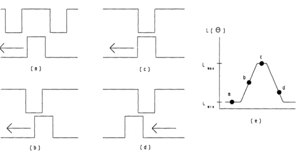
(b) (d)Figure 2.2 Idealized variation of phase inductance with rotor position. (a)
Minimum inductance. (b) Inductance increasing linearly. (c) Maximum inductance. (d) Inductance decreasing linearly. (e) Inductance vs. position (not to scale).
where po is the permeability of free space, N is the number of turns, A, is the cross
sectional area of overlap between the stator pole and rotor pole, and g is the air gap length. When a stator pole and rotor pole are completely unaligned, g increases to an effective gap between the stator pole and the side of the nearest rotor pole, giving a
small inductance. As the rotor turns, each phase's inductance can be in one of four
conditions: (1) minimum when the poles are unaligned (Lm), as shown in Fig. 2.2(a);
(2) increasing linearly when the poles' alignment is increasing, as shown in Fig. 2.2(b);
(3) maximum when the poles are aligned (La,) as in Fig. 2.2(c), and (4) decreasing
linearly when the poles' alignment is decreasing, illustrated in Fig. 2.2(d).
2.2.2 VRM Practical Considerations
A VRM will not operate properly if connected directly to an ac or dc power
tn
tn
-L(e
)
L(e
)
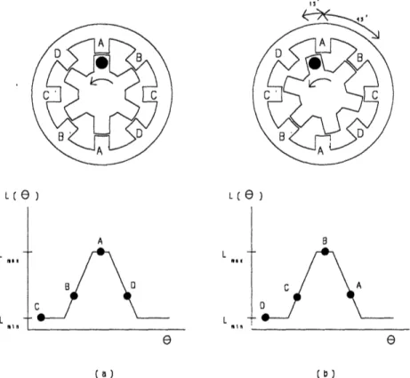
L -I -fin A L -IL _ __ a _ E e (a) (b)Figure 2.3 (a) Rotor position and inductance of the four phases with phase A
aligned. (b) Rotor position and inductances for phase B aligned. The stator flux wave shifted 450 CW; the rotor turned 15°CCW.
source. Proper operation of a VRM requires a continuously active controller which energizes and de-energizes the stator phases at the proper rotor positions. Thus, a VRM requires a closed loop control system with position feedback to apply the stator mmf to each phase at the appropriate rotor position.
The direction of rotation of the VRM rotor is opposite to the direction of rotation of the stator phase excitation. If the stator phases are excited in a clockwise
sequence, the rotor turns counterclockwise. Since the stator poles repeat every 45° and the rotor poles repeat every 60°, shifting from phase A to phase B forces the rotor to
V
supply
D1
2
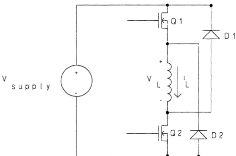
Figure 2.4 Simplified circuit for a single phase of the VRM inverter.
A aligned and then phase B aligned. For every complete revolution of the stator flux, the rotor turns only 1/3 revolution in the opposite direction.
2.3 VRM Inverter Operation
The VRM requires an inverter and control system to operate properly. VRM torque does not depend on current direction because of the i2 term in (2.10). This
allows the use of unidirectional current switches in the inverter. The basic inverter circuit for each phase consists of the phase winding, two field effect transistors (FET)
with gate signals supplied by the controller, and two freewheeling diodes. Figure 2.4
shows a simplified circuit for one phase. Appendix A contains the wiring diagram for
the inverter and all other circuitry. The inverter can be operated in two modes:
2.3.1 Normal Operation
The normal operating mode minimizes the amount of switching in the inverter. Switching accomplishes two functions: commutation between phases based on rotor position, and current chopping to maintain the desired phase current. The controller provides the current setpoint and on/off signals. The current setpoint defines a hysteresis band to maintain an average current at a user specified value. Refer to Fig. 2.4 for the following discussion of normal mode operation.
There are four possible states for the inverter:
State 1: Q1, Q2, D1, D2 off
State 2: Q1, Q2 on; D1, D2 off
State 3: Q2, D2 on; Q1, D1 off
State 4: D1, D2 on; Q1, Q2 off
Assume the initial condition is State 1 where all devices are off. At the proper position, the controller sends the ON signal, which forces State 2 by turning on Q1
and Q2. In State 2, VL = vsupp1y is applied across the phase winding, and iLramps up
with the relationship
diL = VL (2.12)
dt L
At some point, iL reaches the high current level defined by the hysteresis band. To prevent iL from increasing indefinitely, the controller turns Q1 off, forcing D2 on, and
the inverter enters State 3. The phase winding then begins discharging its magnetic
determined by (2.12), where the induced negative VL is just the short circuit voltage
drop across the two conducting devices, Q2 and D2. This small voltage drop allows current to ramp down slowly. When iL reaches the low current level defined by the
hysteresis band, the controller sends the inverter back to state 2 by turning on Q1.
This current chop cycle repeats until the rotor reaches the off position, where the controller turns off Qland Q2 and the inverter enters State 4. The phase winding discharges its magnetic energy by maintaining current flow, forcing D1 and D2 to turn on. The induced voltage across the phase winding is VL = -vsupply, which allows iL to
rapidly ramp down to zero, at which point D1 and D2 turn off and the inverter returns
to State 1.
The current chopping strategy used in the normal mode is called soft chopping,
since only one of two transistors is switched to maintain current level. Q1 and D2 are
called the "chop transistor" and "chop diode." Q2 and D1 are called the "commutation
transistor" and "commutation diode" because they change state during commutation
and not during current chopping. This distinction is arbitrary, because Q2 and D1
could do the chopping.
2.3.2 Regenerative Operation
The regenerative operating mode produces a higher switching frequency than the normal operating mode. Both FETs are switched together for chopping and
commutation. Refer to Fig. 2.4 for the following discussion of the regenerative mode. There are three expected states for the inverter:
State 2: Q1, Q2 on; D1, D2 off
State 3: D1, D2 on; Q1, Q2 off
Assume the initial condition is State 1 where all devices are off. As in the normal
mode, Q1 and Q2 are turned on by the controller at the proper position to produce torque, and the inverter enters State 2. At the high current level, current chopping is accomplished by turning both Q1 and Q2 off, forcing the inverter to State 3. The negative voltage -v,,,upp is across the phase winding, causing iL to rapidly ramp down by the relationship in (2.12). At the lower current level, the controller turns on both FETs and sends the inverter back to State 2. The two states where one FET is on and
the other is off are possible due to unequal circuit delays; these cases would cause a
temporary condition like State 3 of the normal mode where the phase winding discharges through one FET and one diode until the other FET responds to its gate control signal. At the turn off point, the inverter is sent to State 3 where it remains until the phase winding has discharged completely. When there is zero current
through the diodes, the inverter returns to State 1 to wait for the next ON signal from the controller.
The current chopping strategy used in the regenerative mode is called hard chopping. Chop frequency is higher than in the normal mode since i, ramps down faster during chopping. The mode is called regenerative because the phase winding returns energy to the dc supply's capacitor during chopping.
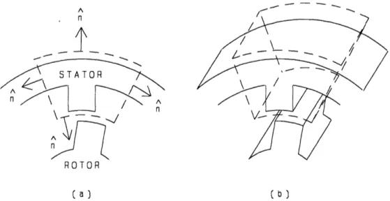
A
-n
_J
ROTOR
(a) (b)
Figure 2.5 (a) 2D view of closed surface for calculating forces on the stator. Normal directions shown in radial and tangential directions. (b) 3D view of closed
surface.
2.4 VRM Acoustic Noise
A VRM is a noisy motor[1,4,5,11]. Two basic factors contribute to this noise:
the doubly salient construction of the rotor and stator, and the frequency components
of the phase current.
2.4.1 VRM Noise Sources
A doubly salient VRM is noisy for a very simple reason: the strong pulsating
radial magnetic forces cause frame distortions which are transmitted to the
surroundings as acoustic noise. A singly salient VRM is less noisy, but also produces
less torque.
Cameron's experimental work showed that radial vibrations of the stator are the dominant noise source in the VRM[4,5]. Maxwell stress tensor analysis can be used
-to determine the equation for the radial forces on the sta-tor. Figure 2.5 shows the
surface used for the integration. The closed surface surrounds a stator pole, and is conveniently chosen so that its surfaces are perpendicular to the longitudinal, radial and tangential directions. Some reasonable assumptions simplify the derivation. The
flux in the air gap is radially directed, and uniform where the air gap is uniform. The
flux is negligible where the poles are not aligned. Fringing effects are ignored, and the permeability, p, of the stator and rotor is infinite compared to P. This leaves a
component of the magnetic field intensity H in the radial direction only, Hr.
The net force f on the surface in any direction m can be described by the
equation
fms = ffld, 1o(HmHn -
.2
Hf)
d
=
fffv
FjldV (2.13)where H is the magnetic field intensity, $ is the Kronecker delta, m is the unit vector
in the m direction, is the outward pointing normal, and Fm is the force density.
Given the above assumptions, the only nonzero force is in the radial direction, and
(2.13) simplifies to
f, V rLA , (2.14)
f
f flad
2
,Z
The normal vector points toward the center and the unit vector , points away from the center, so the dot product produces -1. The surface integral reduces to the surface between the rotor and stator pole, with the area dS equal to At(O) which is the cross sectional area of overlap between the stator and rotor poles.
The radial force can be related to circuit parameters by making the substitution
H Ni (2.15)
2g
where N is the total number of turns on the phase (including both poles), i is the
current through the phase winding, and g is the air gap length between a stator and
rotor pole. Substituting (2.15) into (2.14) yields the equation for the radial force on the stator pole
=o A,(o) N2i2 (2.16)
8g2
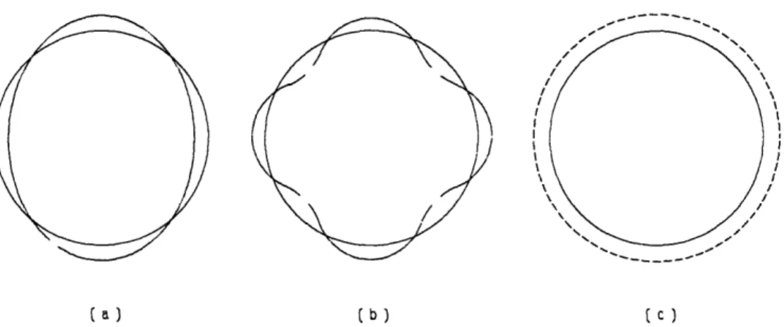
The result of (2.16) is that the stator poles are pulled toward the rotor when that phase is energized. Cameron's experimental results show that the net deflection is on the order of a micron for the experimental VRM used in this thesis. The modes of vibration also affect the acoustic noise. Three modes of mechanical resonance in the acoustic range exist for the experimental VRM: single ovalization at 2604 Hz, double ovalization at 9200 Hz, and a uniform expansion/contraction or breathing mode at
14200 Hz. Figure 2.6 shows the three modes.
2.4.2 Inverter Drive Contributions to VRM Acoustic Noise
The inverter control strategy used to drive the VRM also affects acoustic noise emissions. In broad terms, the frequency of the applied signal excites mechanical
frequencies of the stator to produce noise. From (2.16), i2 is a factor in determining
the magnitude of the radial vibrations of the stator. Current is supplied to the VRM
11 \
,
I;
' \/, ,,I~ /,,~~~~~I XN \\ ~~~~~~~~~/III \\ ~~~~~~~~// \\ ~~~~~~~// \\ ~~~~// (a) (b) tC)Figure 2.6 Stator vibration modes. Dashed lines show the deformations (not to
scale). (a) Single ovalization of the stator. (b) Double ovalization of the stator. (c)
Breathing mode of the stator.
acoustic noise. If the inverter coherently excites the stator's resonant frequency, the acoustic noise will be higher. The other variable is the sensitivity of the human ear; frequencies out of range of human hearing are not troublesome, while frequencies near the average ear's maximum sensitivity in the vicinity of 3kHz are of considerable concern.
The major contribution of the inverter drive to VRM acoustic noise comes from the current commutation frequency. For the 8/6 VRM, the fundamental frequency of
each phase is 6 times the rotor speed. Each phase commutates on and off for each
rotor pole passage, thus with 6 rotor poles a stator phase winding undergoes 6 current fundamental periods per revolution. The fundamental mechanical excitation of the VRM as a whole occurs at 24 times the rotor's rotational speed (6 poles x 4 phases). The use of unidirectional current switches gives double the excitation frequency of
L
(
e)
ON OFF time ON OFF time
or or
[(a ) [(b)
Figure 2.7 (a) Plot of current vs. time (position) during the time a phase is
energized. The scale is exaggerated for clarity to show the decrease in frequency as inductance increases. (b) Plot of inductance vs. time during the same period.
bidirectional current switches.
Experiments on an 8/6 VRM have shown that, although the predominant noise peak always occurred in the same frequency band regardless of speed or load, lower
levels of noise did occur at 24 times the speed. The predominant noise peak
corresponds to a mechanical resonance of the stator. Additional noise components were observed at integer multiples of the fundamental pulse frequency[ 10].
Another contribution of the inverter drive to VRM acoustic noise is the current chop frequency. This frequency is significantly higher than the commutation
frequency, with the regenerative mode producing a higher frequency than the normal mode. It must be noted that the current chop frequency is not a constant. From (2.12), the time derivative of iL is inversely proportional to phase inductance for a given VL. Since L is a function of position, and increases while the phase is energized
and pulling the rotor pole into alignment, the instantanteous chop frequency decreases as pole overlap increases. Figure 2.7 illustrates the changing chop frequency with increasing inductance. If the switching frequency of the inverter during current
chopping is in the audio range, as in the laboratory setup, then current chopping also
contributes somewhat to acoustic noise.
Some research has attempted to quantify the contribution of an inverter to motor noise. In general, non-sinusoidal voltages applied to a motor's phase winding produce higher acoustic noise than sinusoidal voltages produce[12,13]. These
non-sinusoidal voltages produce harmonics which excite different modes of stator
distortion. Much of the research comes to the same conclusion: when a harmonic of a non-sinusoidal phase voltage coincides with a spectrum component of the
electromagnetic noise produced by the motor at a natural frequency of the stator, a
high noise level results[12,13,14]. Based on this research, the inverter drive plays an important role in determining motor acoustic noise.
The work in this thesis investigates acoustic noise generated from commutation of the stator phases. This noise is in the range of human hearing. At a rotor speed of 5000 rpm the fundamental frequency of the VRM is 24 times higher at 2 kHz.
Several harmonics of the commutation frequency also fall within the range of human hearing. The contribution of current chopping and the inverter to acoustic noise is
also a consideration, even though it is at a lower dB level than the commutation noise.
Its frequency, which is a function of supply voltage, phase inductance, and chopping method, could possibly be more annoying to the human ear than commutation noise.
There is some evidence that soft chopping produces less acoustic noise than hard chopping. There is also some evidence that using voltage pulse width modulation (PWM) instead of current chopping produces quieter operation[1 1]. All experiments in this thesis were conducted using hard or soft current chopping.
There are many potential benefits of a reduction in a motor acoustic noise
through randomization, and there is more research to be done. If a VRM or any other
motor can operate quieter through changes in its control system, there is no need for
an expensive mechanical redesign. Another solution to noise problems in use today is
increasing inverter switching frequency, which increases switching power losses. This thesis demonstrates the effects of randomization of the commutation points on acoustic
Chapter 3
CONTROLLER OPERATION
The controller for the VRM laboratory setup incorporates hardware and software to send the appropriate signals to the VRM inverter. The main element of the control system is the Motorola 68332 Microcontroller Unit (MCU). It performs real-time calculations to implement randomization schemes based on user input. The MCU and controller hardware provide ON and OFF signals to inverter FET gate circuits, thus controlling VRM phase currents and torque.
The necessity of position feedback and current chopping for proper VRM
operation is described in Chapter 2. The control system for the VRM uses two
feedback loops to accomplish these functions. A digital outer loop provides the
commutation ON and OFF signals, while an analog inner loop regulates the phase
currrents for the active phases. In the outer loop, MCU software determines the ON and OFF points for each stator phase using position feedback from the VRM via an optical shaft encoder. An IBM XT personal computer provides a user interface to the MCU. Figure 3.1 shows a block diagram of the major components of the VRM
Dana+ eFrnP-rnr Mrriin+ln- P D 1 4-e
Figure 3.1 Block diagram of the VRM laboratory setup including inverter, control system and user interface.
laboratory setup. Appendix A contains circuit wiring diagrams. The rest of this chapter describes the elements that form the control system.
3.1 Optical Shaft Encoder
A Hewlett Packard'HEDS-5000 optical shaft encoder provides the position feedback necessary to determine rotor position. The stationary body of the encoder is
mounted on a plate which stands off 2 inches from one end of the VRM. A code wheel is mounted on the rotor shaft, and positioned inside the body of the shaft
encoder. Figure 3.2 shows the mounting of the shaft encoder. The shaft encoder uses three light emitting diodes (LEDs). Collimated light from the LEDs passes through
slots in the code wheel to photodiodes, which produce three output signals called
channels A, B, and I. The LEDs and photodiodes for Channel A are offset from those for Channel B, while sharing the same slots, to produce square wave outputs in
quadrature (phase difference of 90 degrees). Although it is possible to produce 800 pulses per revolution from the 200 mechanical slots in the code wheel by a logical
XOR of channels A and B, only 200 pulses per revolution are used, as explained in
Section 3.2.1.
The best angular resolution from the shaft encoder of 0.45 mechanical degrees
per revolution was considered too low to allow a variety of randomization schemes.'
Because the range of increasing inductance for each phase covers only 21 mechanical degrees, variations of ON and OFF points up to only 2 degrees were permitted.2 The best shaft encoder resolution would allow only five possible states for a 2 degree variation. Code wheels with more slots were available, but a better solution was to use MCU features which provided a much greater resolution. Section 3.2.1 describes how the MCU further divides the position count to achieve high resolution. An MCU limitation only allows the use of one channel for position count. Channel A is not used, and Channel B gives a position count resolution of 1.8 mechanical degrees from the shaft encoder.
Channel I, the third output channel from the shaft encoder, is an index signal which produces a pulse only once per revolution. It uses slots at a different radius
'360 deg/rev * 1 rev/800 slot
2Uniform variation of the ON point by only 2 degrees from the nominal ON point would
OpticO
Shaft
Encode
Codi
Whe
Figure 3.2 Side view of VRM showing shaft encoder mounting
than those for channels A and B. By resetting the cumulative pulse count from channel B to zero every time an index pulse is detected, correlation is achieved between rotor position and pulse count. The pulse counts corresponding to alignment of each rotor pole with each stator phase were determined using a separate circuit containing an up/down counter with a reset. The phases were energized one at a time, the rotor was moved to the six positions of maximum alignment for the phase, and the count recorded. The unaligned positions were determined from the aligned positions and motor geometry, because the unaligned positions are positions of unstable
equilibrium.
3.2 Motorola 68332 Microcontroller Unit (MCU)
The MCU used in the laboratory setup is part of a promotional evaluation system developed by Motorola, the Motorola 68332EVS. It sits on a platform board that contains the MCU, one parallel and two serial RS-232 compatible input/output (I/O) ports, 32k x 16 bit random access memory (RAM), 64k x 16 bit erasable programmable read only memory (EPROM), and convenient pinout logic analyzer connections that fit standard connectors. The assembler and In Circuit Debugger (ICD) used in controller development were provided by P&E Microcomputer Systems, Inc., of Woburn, Massachusetts.
The MCU contains separate stand-alone modules which provide functions that facilitated design of the control software. These modules operate independently, simultaneously with the Central Processor Unit (CPU). Most of the MCU's modules were not used in the final design. The Serial Control Interface (SCI) allows
communication between the MCU and IBM XT via an RS-232 connection using communication interface software contained in the ICD. The time-related requirement for randomizaton was fulfilled by using the Time Processor Unit (TPU). This module provides the phase commutation signals and is described in the next section.
References [15]-[17] are reference manuals for the MCU.
3.2.1 Time Processor Unit Operation
The TPU contains 9 separate timing functions for control of external devices. These functions can be programmed on any of the 16 available TPU channels. Two
uses an input signal derived from the shaft encoder, and operates in the Period Measurement with Missing Transition Detection mode (PMM). This function mode allows measurement of the pulse period between normal, regularly occurring input transitions. Pulses from the shaft encoder provide the single input signal, with channel B and channel I signals logically NANDed to produce a regular pulse train with a missing transition once per revolution. This missing transition allows the TPU to determine its position every revolution and at startup. The TPU module is designed for angle-based engine control, and with appropriate software can be used to
implement myriad randomization schemes.
The critical parameter for the TPU is the pulse period, which is 1/200th of a revolution. Each pulse period represents 1.8 mechanical degrees, with 199 pulse periods and one missing transition per revolution. The pulse period measurement is a 23 bit count of clock cycles between shaft encoder position pulses, stored in register TCR1. A separate register (TCR2) counts shaft encoder position pulses from 0 to 198, and resets whenever the missing transition is detected. The missing transition is
detected by a delay between input pulses, with the delay trigger set in software to 1.5 pulse periods. The previous pulse period is always used for calculations, allowing the MCU to respond accurately to speed changes and speed ripples.
Eight TPU channels are used to produce the ON and OFF signals for the four stator phases. Channels 1 through 8 operate in the Position-Synchronized Pulse
Generator (PSP) mode. Once initialized and synchronized to the input pulse sequence, the PSP function continually generates output pulses based on ANGLE and RATIO
parameters. For each PSP channel, ANGLE is the position count corresponding to
the ON (or OFF) point. The ANGLE register has only 8 bits, which makes 256 the
maximum allowed number of pulses per revolution. For this reason, only 200 of the 800 possible pulses per revolution from the shaft encoder were used for position count.
Each PSP timing function uses a fractional multiply to resolve position down to a precise angle. RATIO holds the value for calculating a fraction of a pulse period for ON and OFF point angle resolution. When the count in TCR2 matches the position
indicated by ANGLE, RATIO is used to determine when the channel should output a
control signal pulse. The 8 bits in RATIO divide two pulse periods into 256 positions, using the previous pulse period measurement from TCR1. This fractional multiply increases resolution to 1/128 of 1.8 mechanical degrees, which is sufficient to implement randomization schemes. The PSP output pulses are sent to a flip-flop whose output controls phase commutation. The duration of the control signal output pulse from a PSP channel is one pulse period, and the signal is used to PRESET or CLEAR a D flip-flop. The flip-flop stores the phase's commutation state.
Each phase of the VRM is turned on and off six times per rotor revolution, as discussed in chapter 2. Thus, ANGLE and RATIO parameters for each phase's ON and OFF points are updated six times per revolution. Nominal ON and OFF points are stored in a table in the controller software. Randomization schemes are
implemented on a real-time basis by adding to or subtracting from the nominal ON and OFF points for each phase, and placing the values in the ANGLE and RATIO
3.2.2 Software Development
The software used in the control system was developed using the ICD, which allows parallel communication between the MCU and IBM XT for downloading programs and debugging. A separate serial communications cable allows user interface with the MCU by using the IBM XT as a dumb terminal. Appendix B contains a program listing of all MCU software.
The hardware features of the MCU TPU described in section 3.2.1 minimize
the operations that the software has to perform. The MCU clock rate of 16.78 MHz is
high enough that the 24 sets of calculations required for randomization of the ON and OFF points for all phases each revolution can be accomplished in real-time.
Calculations for a phase's subsequent ON and OFF positions are conducted during the opposite phase's ON period. The calculations are initiated by TPU generated
interrupts. Phases A and C are opposite, as are phases B and D. Randomization
schemes and the timing sequence of the phases are described in chapter 4.
Software is used to allow user input to the MCU. In the initialization routine,
the MCU prompts the user to select which pre-programmed randomization scheme to use. Choices are described in Chapter 4. The control software is designed such that the laboratory setup is a general test bed for applying randomizations schemes. Additional randomization schemes can be inserted with minimal effort.
3.3 Controller Hardware
Controller hardware consists of two separate circuit boards, which combine to send signals to the FET gate drivers on the inverter board. The MCU interface board's sole purpose is to provide electrical isolation between the MCU and other hardware. The inverter controller board is a modification of the current-mode controller hardware developed by Cameron[4]. Phases A and C share much of the same controller
hardware, as do phases B and D, which reduces the amount of hardware required. This arrangement is possible since opposite phases are never on at the same time.
3.3.1 MCU Interface Board
The MCU interface board provides electrical isolation between the MCU and logic/analog circuitry on the Inverter Controller board. It uses Darlington
optocouplers, which have a relatively fast response time of 40 nsec.
Signals that could be defined in software were eliminated in the late stages of design to minimize the number of optocouplers. In the initial design, an eight bit digital to analog converter allowed setting the current chop level through the user interface to the MCU. Electrical isolation would have required eleven optocouplers, and was not cost effective. The eight TPU channel signals are coupled from the MCU
to the Inverter Controller, and the index signal and PMM signal are coupled from the
Inverter Controller to the MCU.
3.3.2 Inverter Controller Board
The inverter controller board contains the shaft encoder connection to the VRM, current chopping and commutation hardware. It produces the gate control
signals for the FET gate drivers. It uses a sampled hysteresis control scheme to control motor phase current. The feedback loop for current chopping is composed of analog hardware. Linear Hall effect sensors are used to detect motor phase currents.
Opposite phases share Hall effect sensors and current chopping circuitry. Each hall effect output is a voltage level, which represents current level feedback from the VRM. Inverter mode is set to normal or regenerative with a toggle switch. The current chop setpoint is determined by a potentiometer.
Eight outputs from the MCU TPU channels configured for the PSP function are sent to the MCU interface board. These signals either preset or clear the flip-flop for the proper phase. The four outputs from these flip-flops are the phase commutation
signals, where a logical 1 means ON and a logical 0 means OFF. These commutation
signals are combined with the current chopping signals to control the FET gate drivers. Current chopping is achieved by comparing the present current level to the setpoint. The output of the Hall effect sensor with zero current through it is nominally 6V. The current setpoint reference level is set to match the Hall effect sensor zero
current output voltage using a potentiometer. Current chop level is set with a second
potentiometer, with a voltage scale of 0.24 volts/amp to match the sensitivity of the Hall effect sensors. The current chop level is added to the current setpoint reference level to produce the voltage necessary to cause current chopping. Actual current level
and inverted current setpoint signals are summed and sent via buffer stages to a
flip-flop. At the current limit, the flip-flop input is pulled low, and the next inverter controller clock pulse places a logic 0 at the output to turn off the appropriate FETs.
As current falls, and Hall effect sensor voltage falls below the setpoint voltage, the Schmitt trigger output changes to set the flip-flop. The Schmitt trigger hysteresis band
represents 0.2 amps. Flip-flop clock frequency is set to 30 kHz. Flip-flop output is
logically combined with the mode and commutation signals to send the appropriate ON and OFF signals for each FET to the inverter board.
The Inverter Controller gives a FET an ON (OFF) signal when three conditions
are met: (1) the commutation signal from the microprocessor indicates the phase
should be on (off), (2) the current chop circuitry indicates the current is below (above) the setpoint, and (3) the mode control switch indicates the FET should be turned on (off).
3.3.3 Inverter Board
The inverter board contains the 4 phase inverter circuits described in section 2.3, gate drivers for the FETs, optocouplers for electrical isolation, and the Hall effect sensors. One IR2110 gate driver per phase provides gate signals to the low and high side FETs. Each gate driver has a floating power supply for the high side FET. The optocouplers between the Inverter Controller board and Inverter board give the VRM circuitry a third separate ground. Thus, power ground is separated from logic ground
which is separated from MCU ground.
The IR2110 is very sensitive to inductance in its output circuit. In the initial layout of the inverter board, leads between the IR21 Os and the FETs were too long and placed too much inductance in the gate signal path. When an IR2110 received an
This step change in voltage caused ringing, and the oscillation triggered an
undervoltage lockout in the IR2110 which reset the gate signal to zero and turned off
the FET. This problem was solved by four changes to the initial inverter design: 1)
The inverter board was rewired and the IR21 10s physically placed very close to the
FETs to minimize lead inductance. 2) Gate resistors were added to damp LC
oscillations during turn-on, with parallel diodes for quick turn-off. 3) Tantalum and
ceramic disk capacitors in parallel were placed across the low and high side IR2110
power supplies for better high frequency response. These capacitors were physically
placed very close to each IR2110. 4) Each high side voltage source was changed
from a bootstrap capacitor to a transformer with rectifier.
3.4 Fault Tolerance
The fault tolerance of the VRM and its associated controller is considered high compared to that of other motor drives for a couple of reasons[l 1,18]. First, the power electronics for each phase are completely independent from the power
electronics for all other phases. The VRM can still produce torque with a fault in one
or more phases if the rotor's inertia allows the rotor to rotate through the position
where the faulted phase or phases would be the only source of torque. Operation
would be degraded because of an increase in torque ripple.
Inverter design plays a role in VRM fault tolerance. In ac inverters used in
other motor drives, the high and low switches (FETs or some other device) are
switch also shorts the dc power supply when the other switch turns on. In the VRM's inverter, a shoot-through path does not exist with a switch failure because a stator phase lies between the switches. A short circuit fault in the high or low switch places dc supply voltage across the phase winding without affecting power to the other phases. Separate fuses for each phase ensure that the other phases can continue operation in the event of a short circuit fault in one phase, of one FET in the normal
mode or both FETs in the regenerative mode.
Another reason for the VRM's high fault tolerance is the lack of rotor
excitation. The rotor does not follow a rotating mmf that produces torque as in an ac motor. If there is a fault in one phase, the other phases continue to operate unaffected. Because the rotor has no field winding or permanent magnet, there is no generated
Chapter 4
RANDOMIZATION SCHEMES
The use of various randomized switching functions and their effects on power electronic converters and motor drives has been the topic of much recent
research[6,7,8,19]. This thesis quantifies the effect of several different randomization
schemes on the acoustic noise produced by an experimental VRM. A common
framework for applying randomization schemes is presented in this chapter.
Terminology and definitions provided in this chapter are used in Chapter 5 to describe the experimental results.
4.1 Commutation Points
The position feedback of the controller described in Chapter 3 provides the commutation signals at the ON and OFF points. When a phase is on, it produces unidirectional torque and its current is limited by the current chopping hardware. When a phase is off, it does not contribute to torque.
4.1.1 Nominal Timing Between Phases
/i~~i
L~~~~~I
~~D PhaseC Phase
B Phase
A Phase
time/positi( Figure 4.1 Nominal timing relationship between the control signals for the four
phases.
while the VRM is operating. Two phases are energized at the same time during an overlap period. Only one phase is energized 60% of a revolution, and two phases are energized for the other 40% of a revolution. Figure 4.1 shows the nominal timing relationships between the four phases.
Note that phases A and C are opposite; only one of them is energized at a
given time. Phases B and D are also opposite. Angular separation between the OFF
point of one phase and the ON point of its opposite phase is nominally 9 mechanical degrees. This separation allows randomization of both ON and OFF points without energizing opposite phases at the same time. If dc supply voltage is relatively low and the current setpoint is relatively high, the discharge rate of a phase at the OFF point
could be slow enough that opposite phases have non-zero current flow at the same time. This is undesirable for two reasons: 1) the phase turning off is producing
negative torque, and 2) the shared Hall effect sensor could cause the on phase's current to chop at less than the current chop setpoint because of the addition of the current from the phase turning off.
4.1.2 Nominal ON and OFF Points
A simplified description of VRM operation is presented in Section 2.2. In Fig.
2.7, the nominal ON point is shown at the transition between the unaligned position
and the region of increasing overlap of the stator and rotor poles. However, there are other considerations which give more desirable relative positions for the nominal ON and OFF points.
The nominal ON point has a significant effect on torque, but can have a small effect on acoustic noise. To understand this, suppose that phase A is off and all rotor poles are in the unaligned position with respect to phase A. Inductance for phase A
is minimum per the discussion in Section 2.2. The major source of acoustic noise, as
discussed in Section 2.4, is radial vibrations of the stator. The radial force which causes these vibrations, from (2.16), is inversely proportional to the square of the air
gap length (g2). Thus, when the phase A is not aligned with any rotor pole, energizing
it would not produce any significant radial force. Phase A could be energized at any point while it is unaligned without contributing any significant acoustic noise.
Continuing with the phase A example, if phase A is turned on while it is in the
(2.12). When a rotor pole begins overlapping phase A, current could already be chopping, which would allow maximum torque production per (2.10).
The case for the nominal OFF point is basically the opposite of the case for the ON point. Current through the phase when inductance is maximum (at the position of maximum alignment) does not contribute to torque. If current is still present when pole alignment starts decreasing from maximum, a negative torque is produced.
Additionally, the larger inductance at maximum alignment gives a longer time constant (L/R), which could also contributes to phase current being present when alignment starts decreasing. This was observed during initial experiments with low voltage (30V), high current (4A) and no mechanical load on the VRM at approximately 1500
rpm. When the current chop level was decreased, with no change to voltage or
controller operation, VRM speed increased.
Current through the phase at maximum alignment affects acoustic noise,
because the radial force on the stator is at its maximum value. When the phase is
turned off, the radial force decreases as current falls, which contributes to stator
vibration. There is experimental evidence to support the conclusion that the OFF point transient produces more acoustic noise than the ON point transient or current
chopping[20].
The optimum case for the ON point which gives maximum torque production
and minimum acoustic noise is to have the ON point during the unaligned position,
allowing current to begin chopping by the time inductance starts to rise as the poles
on acoustic noise because of the small radial forces. Randomizing the ON point over a range of increasing alignment decreases the power delivered by the phases.
The optimum case for the OFF point is to turn the phase off while the stator pole is completely overlapped by the rotor pole, and early enough that phase current
has enough time to decrease to zero before pole alignment starts to decrease.
Randomizing the OFF point varies the spectral content of the stator vibrations, and the
effects on acoustic noise are described in Chapter 5. For the reasons discussed above,
most of the randomization schemes involve dithering the OFF point. References [11]
and [21] further discuss these issues.
4.2 Randomization Terminology
A standard terminology is introduced here to allow comparisons between the
different randomization schemes. The terminology used is taken from [8], [22] and
[23]. All randomization schemes begin with the same information, the nominal ON
and OFF points for each phase. How these ON and OFF points are changed during randomization defines the type of randomization.
4.2.1 Waveform Description
All the randomization schemes used in the experiments are periodic, with the period for each phase equal to 1/6 of the time per revolution. If one makes the simplifying assumption that torque ripple is negligible, the period is equal to the time between successive nominal ON (or OFF) points. The start of each period is
I I I - t h c y c I e T | l I l I KC X > ti me e a
Figure 4.2 Classification of basic random switching terminology.
transition at the ON point and 1-0 transition at the OFF point are completed somewhere in the middle of the period.
Three parameters are necessary to describe the basic switching cycle. Figure 4.2 shows their temporal relationship during an arbitrary i-th cycle. Let Ti be the duration of the i-th cycle. The position of the ON point in the i-th cycle is given by
ei, and the on-time is given by a (the time between the ON and OFF points). This
gives a duty ratio di = aT,. These definitions are rigorous for the phase control signals, but are only an approximation of the current waveform. Each control signal transition defines a phase commutation ON or OFF point, but does not show the current chopping that occurs between the ON and OFF points. Chopping is influenced
by the hysteresis set in the controller hardware. Only the timing of the ON point and
OFF point are well-defined, because the rise and fall times of current during
1 I I I I I i i I I I i