Document oo!m,,Dg ROOM 36-412 Research Laooratory of Electronics
assachusetts Institute of Technology
e ouetIolD~QR~1 OY3-1
BOUNDS TO THE ENTROPY OF TELEVISION SIGNALS
JACK CAPON
TECHNICAL REPORT 296
MAY 25, 1955
RESEARCH LABORATORY OF ELECTRONICS
MASSACHUSETTS INSTITUTE OF TECHNOLOGY CAMBRIDGE, MASSACHUSETTS
*
~c9
The Research Laboratory of Electronics is an interdepartmental laboratory of the Department of Electrical Engineering and the Department of Physics.
The research reported in this document was made possible in part by support extended the Massachusetts Institute of Technology, Research Laboratory of Electronics, jointly by the Army (Signal Corps), the Navy (Office of Naval Research), and the Air Force (Office of Scientific Research, Air Research and Development Com-mand), under Signal Corps Contract DA36-039 sc-42607, Project 102B; Department of the Army Project 3-99-10-022.
MASSACHUSETTS INSTITUTE OF TECHNOLOGY RESEARCH LABORATORY OF ELECTRONICS
Technical Report 296 May 25, 1955
BOUNDS TO THE ENTROPY OF TELEVISION SIGNALS Jack Capon
This report is based on a thesis submitted to the Department of Electrical Engineering, M.I.T., 1955, in partial fulfillment of the
requirements for the degree of Master of Science.
Abstract
Statistics of pictures were measured, including the second-order probabilities of successive cells and the autocorrelation function. These quantities, obtained by independent methods, are used to compute an upper bound to the entropy per sample. The results are compared and used to estimate the amount by which the channel capacity required for television transmission might be reduced through exploitation
INTRODUCTION
This research is an application of statistical communication theory to television transmission. An upper bound to the entropy per symbol is obtained by two independent
methods. It is shown that this quantity not only provides an insight into the nature of pictures but furnishes a theoretical limit to the efficiency of picture-coding methods.
In Section I the basic concepts of information theory are introduced. The wasteful-ness of nonstatistical versus statistical coding is brought out in a general discussion of the coding problem.
Section II explains the scanning process and the standards used in commercial tele-vision transmission. The bandwidth requirement is shown to arise from the necessity of transmitting sharp changes in brightness such as those that appear at the edges of objects. It is shown that these changes occur in only a small portion of the picture.
Large parts of the picture exhibit very low gradients in brightness. This phenomenon and the similarity of successive frames cause the video signal to have a low information content; since a picture with a high information content would be a random pattern, the low information content is assumed to be essential to the nature of pictures.
Section III contains details of the measurement and calibration procedures. The effect of the noise on the probability measurement is discussed. An exact analysis for deriving the signal probabilities from those of the signal plus noise is given, but it is pointed out that this method is vulnerable to experimental errors. Upper and lower bounds to the entropy per symbol are obtained and compared with the upper bound obtained by autocorrelation function methods. This, a true upper bound, will be the actual bound only if the process is gaussian.
Results are presented in Section IV, along with experimental procedures and compu-tations. Various sources of error are discussed.
Section V contains an analysis of the results obtained. It is shown that the infor-mation content of pictures depends upon the amount of detail in the picture and the intensity range covered. To obtain a better estimate of the entropy per symbol from the autocorrelation function measurement, an entropy conditioned by three previous samples instead of one is computed. The entropy of the difference signal is also discussed.
The appendices contain derivations that could not properly be included in the main body of the paper.
Previous investigators have measured bounds to the entropy per symbol. W. F. Schreiber (4), of Harvard University, measured second-order probabilities of pictures and computed a bound to the entropy per symbol. E. R. Kretzmer (5), of Bell Telephone Laboratories, measured first-order probabilities and autocorrelation func-tions of pictures and computed a bound to the entropy per symbol; but their results were not obtained from the same set of pictures. This experiment is an extension of their
work but the second-order probabilities, autocorrelation functions, and the bounds to the entropy per symbol were derived from one set of pictures.
I. CODING AND INFORMATION THEORY
1. BASIC CONCEPTS
The theory of communication has taught engineers to examine the content of the messages that they are transmitting from a statistical viewpoint. In the light of this new theory, engineers think of messages in terms of probability of occurrence. It is intuitively obvious that the reception of a signal of small probability conveys much more information than the reception of a signal of great probability. Examples occur fre-quently in everyday life. For example, a report of snow in Boston in August conveys much more information than a report of fair and mild weather.
One of the basic contributions of information theory is the definition of a measure of information that conforms to one's intuitive feelings about information. The basic con-cepts used in our discussions are cited for convenient reference.
In accordance with our previous statement about probability of occurrence, we can say that the information conveyed by a message xi selected from a set X is (see ref. 1,
Chap. II, p. 10)
* I(xi) = -log P(xi)
where p(xi) is the probability of occurrence of message xi .
One sees that for p(xi) = 1, that is, certainty about xi, the information conveyed is
zero. This obeys our intuitive feelings about information, for if an event is known to be certain to occur, its occurrence does not communicate any useful knowledge. On the other hand, as p(xi) is made smaller and smaller, increasing the uncertainty about xi,
the information conveyed becomes larger and larger. This is also in line with our intuitive feelings of what a measure of information should be.
In a similar manner, the information conveyed by a message yj from a set Y, about a message xi from a set X is (see ref. 1, Chap. II, p. 4)
P(Xi I Yj)
I(xi; yj) = log
p(xi )
where p(xilyj) is the conditional probability of xi if yj is known.
This definition is also in accordance with our feelings about information. If the a posteriori is increased so that yj specifies xi more completely, one would expect the
information conveyed by yj about xi to be increased. This is seen to be the case from the definition. We observe that, since the maximum value of p(xilyj) is unity, the
maximum value for I(xi; yj) is -log p(xi). That is, the message yj can convey no more information about xi than that which xi itself conveys. This is another obvious condition
that one would expect the definition of information to obey.
Entropy is defined as the average amount of information that must be provided in order to specify any particular message x from a set X. It is represented by
H(X) = - p(x) log p(x) X
The properties of the entropy that are of importance to the discussion are: If p(x) vanishes at point xi in the set X, then the term corresponding to xi also vanishes:
lim P(xi) log p(xi) = 0, where P(xi) - 0. Thus H(X) is equal to zero when and only when p(x) vanishes at all points but one, in which case p(x) = 1 at the remaining point. This situation corresponds to the case in which only one particular message can ever be transmitted; then, no information can be provided about it because it is completely specified from the start. One might also say that the uncertainty regarding the message set is zero.
For any given set of symbols, the entropy is maximum when all symbols occur with equal probability. If the number of symbols is N, then from the formula for H(X) it is apparent that the maximum value of H(X) is given by log N. In this case the uncertainty about the message set is greatest. It is of interest to note that as the probabilities of the messages become more unequal, the entropy decreases. This is a very important property and will be referred to frequently in following sections.
For the sake of completeness a conditional entropy will be defined as
H(YIX) = - E E p(x; y) log p(y x)
X Y
where p(x; y) is the probability of joint occurrence of events x and y.
This quantity can be interpreted as the average amount of information required to specify the event y if event x should be known. An example of this is found in the transmission of printed English. In this case, the set X corresponds to a particular letter of interest; the set Y to the letter succeeding it. Suppose that we are interested in the letter q, so that the set X corresponds to just this one symbol. We are fairly certain that if we receive a "q" the succeeding letter will be a "u. n Thus, of the twenty-seven symbols in the Y space, u is very probable, and all others improbable. This means that the entropy, or average information, is small - as mentioned before. Let us now examine the letter c, and let the X space now consist of just this symbol. If we know the occurrence of a c, we cannot be too sure of what the succeeding letter will be. It is likely to be a, e, i, o, u, or y and unlikely to be b, d, f, g, or t. In this example
*X in H(X) signifies that an average over the set X has been performed. Although the entropy is a function of the probabilities p(x), H(X) will be the notation used to denote the entropy of a set X with probabilities p(x).
the probabilities of the symbols are more alike than they were in the preceding one. Thus the entropy will be larger than before. This concept of how the conditional entropy changes for different conditional probability distributions is a most important one and, as will be seen later, forms the foundation for the measurements in this experiment.
The final quantity to be defined will be the channel capacity. It is the maximum average value of the mutual information provided by a message y about a message x. Thus
p(x I y)
X p(x)
The p(x y) represents the probability of recognizing x, the transmitted symbol, given the received signal y. It is other than one because of the noise in the channel. The maximizing is done with respect to the transmitter symbol probabilities, p(x).
For a more complete discussion of channel capacity see reference 2. For the pres-ent let us say that the channel capacity of a noisy channel is the maximum possible rate of transmission of information when the source is properly matched to the channel. 2. CODING
Coding, in its most general form, is any process by which a message or message waveform is converted into a signal suitable for a given channel. Frequency modulation, single-sideband modulation and pulse-code modulation are examples of coding proce-dures; any modulator is an example of a coding device.
There are, in general, two classes of coding processes and devices: those that make no use of the statistical properties of the signal and those that do. Almost all of the processes and devices used in present-day communication belong to the first class. In the second class, the probabilities of the message are taken into account so that short representations are used for likely messages or likely sequences, and longer represen-tations for less likely ones. Morse code, for example, uses short code groups for the common letters, longer code groups for the rare ones. These two types of coding will now be discussed.
Messages can be either continuous waves like speech, music, and television; or they can consist of a succession of discrete characters, each with a finite set of possible values, such as English text. Continuous signals can be converted to discrete signals by the process of sampling and quantizing (3). This permits us to talk about them as equivalent from the communication engineering viewpoint. It is generally easier to think in terms of discrete messages. Thus, quantization of continuous signals, if they occur, will be assumed, and we shall think of our messages as always being available in discrete form.
Suppose we have the message set xl, x2, ... , x8, with the probabilities given in
Table I.
Statistical Versus Nonstatistical Coding Message Probability of Occurrence X1 x1 X2 x3 x4 x5 x6 x7 x8 1/2 1/4 1/8 1/16 1/32 1/64 1/128 1/128 Nonstatistic al C oding 000 001 010 011 100 101 110 111
messages were equally likely, the code of column 3 of the average, the number of symbols per message is
Table I would be the result. On
N = 3( + + + + + + + )= (3 X 1)
N = 3 symbols/message
If, now, a statistical coding scheme (Shannon-Fano code) is used (see ref. 1, Chap. III), one arrives at the code of column 4. Although some of the code words are longer, it will be found that the average number of symbols is
N 1( + 2( + 3(8) + 4( 1) + 5( ) + 6( ) + 7( ) + 7(
= 1.98 symbols/message
which is considerably less than the 3 symbols per message obtained previously. This
is a vivid example of how wasteful nonstatistical coding can be.
One of the teachings of information theory is that given a set of messages with certain probabilities, one can set a lower bound to the average number of symbols per message that can be used to code the messages. This lower bound is given by the entropy H(X) associated with the probabilities of the set when a binary alphabet is used (1).
Similarly, if one were to code the second of a pair of messages from a knowledge of the first message, the lower bound would be set by the entropy of their conditional probabilitie s: Statistical Coding 1 01 001 0001 00001 000001 0000001 0000000
H(Yx) =
-Z
p(x; y) log
p(ylx)
X Y
where y is the message succeeding x.
Suppose, now, that one is interested in coding the nth symbol from a knowledge of the (n-l) preceding symbols. The lower bound to the number of symbols per message
is given by
H(AnlAn-I;An-2;;A 1) = - *. P(al; ; a n)
A An
Xlogp(anlanl;.;al)
where ai is the ith symbol in the sequence, and Ai is the space containing the random
variable a..
In the limit as n - Oc, this expression approaches the entropy per symbol (see ref. 1,
Chap. III, pp. 24-25) of the ensemble H(AIA ®) formed by all sequences of length n. From a practical point of view, what does this quantity mean? It tells how many bits of information must be added, on the average, to specify the nth symbol of a sequence from a knowledge of the (n- 1) preceding symbols. How large n is, in general, is determined by how far the statistical dependence extends.
The direct measurement of this quantity is extremely difficult, if not impossible, since it entails the measurement of high-order probabilities. What one does in practice is to find an upper bound for it. It can be shown (see ref. 1, Chap. III, pp. 21-25) that the nt h order conditional entropy for increasing n, constitutes a series of successive
approximations to it. Hence, in this experiment the second-order probabilities and autocorrelation function were measured and from these an upper bound to the entropy per symbol was computed. As we shall point out later these measurements are made
II. THE PHILOSOPHY OF PRESENT-DAY TELEVISION TRANSMISSION
1. PRESENT STANDARDS
A picture can be approximated by an array of dots. The smaller the individual dots are, the greater the resolution of the picture, and the closer the approximation. For a given resolution, the intensity of a dot is a function of two space variables, and of time if the picture is changing. The basic problem in the transmission of pictures is the coding of this function of three variables for transmission through a one-dimensional (time) channel. This is done at present by means of a process known as scanning. The picture is broken up into 525 horizontal lines, and the intensity of every cell in the line is specified. All television pictures have an aspect ratio of four to three, which means that the ratio of frame width to frame height is four thirds. Thus, if the resolution is the same in the horizontal and vertical directions, the picture consists of (525) (525) (4/3) or approximately 366, 000 cells. To create the illusion of continuous motion, the picture is scanned 30 times per second. Actually, an interlace scheme is used, where-by the odd lines are scanned in one sixtieth of a second, and the even lines in the next sixtieth of a second. This, essentially, has the effect of increasing the flicker fre-quency from 30 cps to 60 cps.
An estimate of the bandwidth required can be found by assuming that every cell is different from the succeeding cell in intensity, and that the resulting video waveform is a square wave. Accordingly, for a 525-line picture with an output ratio of 4: 3, the period of this square wave will be
2 T=
(525) (4/3) (525) 1/30
= 0.182 tsec (neglecting blanking time)
To pass the fundamental of this square wave, our system must have a bandwidth of 1
W= T = 5.5 Mc/sec
In practice, the Federal Communications Commission allots 6 Mc/sec to a station and the picture signal occupies 4 Mc/sec of this. Hence, the assumption made about equal vertical and horizontal resolutions is not correct. However, in this experiment the assumption will be made, since the bandwidth of all components used is large enough to give this resolution.
Thus the problem of coding the picture has been solved but at the expense of using a large bandwidth.
2. REDUNDANCY IN TELEVISION TRANSMISSION
According to the dictionary, a picture is a description so vivid as to suggest a men-tal image. To convey its meaning to someone's mind, the picture must be well ordered and must contain few boundaries and vast regions of slowly varying intensity. If this were not so, one would be looking at a picture of white noise (similar to looking at a snow storm) or else at a picture that did not make much sense. However, according to our definition this would not be a picture, since it conveys no meaning. With these ideas in mind, we can say that knowing part of a picture makes it possible to draw cer-tain inferences about the remainder. As a matter of fact, the brightness value of a picture point in a frame is very likely to be nearly equal to the brightness value of the preceding point; the only exceptions occur at boundaries, which, as we know, occupy a small part of the picture. Besides cell-to-cell correlation, there is also correlation between successive frames, which tends to lower the information content of the video signal. If one were to examine these successive frames, he would find that they are almost exactly alike. That this is so is evident from the fact that subject material can-not move very fast. How far can one move in one-thirtieth of a second! In general, then, these picture points are related in a statistical manner, imparting a type of redundancy to the point-by-point description that makes up the video signal.
Commercial television uses a nonstatistical coding scheme and thus does not take advantage of the statistical relationships in the signal. As we observed before (see Table I), this can be costly from the point of view of efficiency of transmission. By means of statistical coding a reduction in the number of symbols per message could be achieved. This means a reduction in the channel capacity, since fewer symbols have to be transmitted. The channel capacity of a channel of band W disturbed by white noise of power N when the average transmitter power is limited to P is given (see ref. 2, pp. 66-68) by
C = W log (1 + ) bits/sec
If by means of a proper coding scheme the channel capacity could be reduced, a potential saving in bandwidth or power, or both, exists. It was pointed out earlier that the greatest reduction in channel capacity is foretold from knowledge of the n-order con-ditional entropy, where n is large and extends over as many previous symbols as have
statistical influence. As we also pointed out, it is extremely difficult to measure proba-bility distributions of an order higher than two. However, an upper bound to the entropy per symbol can be obtained by measuring the second-order probabilities, that is, the probability that a pair of adjacent cells will be at given intensity levels.
An upper bound to the entropy per symbol can also be obtained from the autocorrela-tion funcautocorrela-tion of the picture, as will be shown later. This bound, realized for a gaussian process, will be greater than the bound obtained by the other method and will equal it
these two values obtained by independent methods.
Previously, Schreiber (4) measured second-order probabilities and from the entropy determined that a potential saving of a factor of two or three in channel capacity could be achieved. Kretzmer (5) measured first-order probabilities and autocorrelation func-tions and found that a saving of a factor of two could be effected in the channel capacity.
The following calculation gives an idea of how large the channel capacity is. Goodall (6) found that for a 32-level system, contours would be masked with an input peak-to-peak signal to rms noise ratio of 40 db. For a 4 Mc/sec bandwidth this implies a channel capacity of
= W log2 (1 + P) = (4 x 10⁶) (40 log2 10) = 530 million bits/sec
The magnitude of this figure becomes evident when one realizes that the maximum rate of information reception of the human brain is about 45 bits per second (7). This is another form of redundancy but the exploitation of this form of redundancy is impracti-cal, since it would require knowing which part of the picture each observer was looking
at, that is, which part of the television screen should display the 45 bits. Clearly, this is an impossible feat.
3. A SUMMARY OF AIMS
A list of the quantities to be measured and computed is given for reference purposes. 1. The second-order probability of successive cells in a typical picture is meas-ured. An upper bound to the entropy per symbol is computed, and from this an esti-mation of the saving in channel capacity is made.
2. The autocorrelation function of the same picture is measured, and an upper bound to the entropy per symbol is computed. This value is then compared to the previous one, which was determined by an independent method.
III. MEASUREMENT PROCEDURES
The first part of this section deals with the second-order probability measurement; the last part with the autocorrelation function. It is assumed that a picture is composed
of (525) (525) (4/3) = 366, 000 cells, corresponding, respectively, to the 525 scanning lines used in television transmission and the (525) (4/3) = 700 resolvable elements in a horizontal line. The resolution in horizontal and vertical directions is assumed to be the same. It is also assumed that each cell can have any one of 32 levels of intensity from white to black. This is a reasonable assumption, since it has been found (6) that a 32-level picture is a good approximation for the original.
1. METHOD FOR MEASURING THE JOINT PROBABILITY
The measurement of a probability is basically a counting process. Thus, the most direct method of measuring the joint probability is to cut the picture into 366, 000 parts and count the occurrence of each joint event. This procedure is, of course, laborious. In this experiment television methods are used. The technique for the measurement consists of displaying on the face of a cathode-ray tube a brightness pattern that is pro-portional to the second-order probability. This method was used by Schreiber (4) in his experiment. Kretzmer (5) also used it in his measurement of first-order probability distributions. He employed a clever photographic process to obtain the probability distribution directly from the cathode-ray tube without having to use a photometer to measure the light from the face of the cathode-ray tube. A detailed analysis of this technique with reference to the block diagram in Fig. 1 follows. (For a detailed descrip-tion of the equipment see ref. 8.)
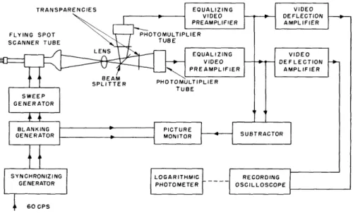
Fig. 1. Block diagram for the measurement of second-order probabilities.
The outputs of the synchronizing generator are 60-cps and 15, 750-cps pulses. They key the blanking generator that produces the blanking and synchronizing pulses delayed by the proper amount. The synchronizing pulses initiate the sweeps of the sweep gener-ator, which drives the deflection coils of the flying-spot scanner tube. This forms a raster of 525 lines on the face of the tube. The light emitted by this raster is focused by the lens on the two transparencies, simultaneously, by means of the beam splitter. The beam splitter consists of a membrane coated with a thin layer of aluminum, so that part of the impinging light is reflected and the rest transmitted. The transparencies are mounted in holders so that one can be positioned with respect to the other. In this manner, the transparencies can be scanned exactly, in register or out of register. That is, when cell i, j is being scanned in one picture, then either cell i, j or cell (i + Ai, j + Aj) in the other can be scanned at the same time.
The light signals generated as a consequence of the scanning are converted to elec-tric signals by the photomultipliers. The video signals are amplified in the video pre-amplifiers and deflection pre-amplifiers, and applied to the horizontal and vertical deflection plates of a recording scope. If the two signals are identical, the resultant pattern will be a 45° line, assuming equal gain and phase-shift through the amplifiers. To get an accurate indication for this condition, the outputs of the preamplifiers are diverted to a subtractor and the difference signal is applied to a picture monitor. If the two trans-parencies are in register, a complete null will be observed on the monitor's cathode-ray tube. If the pictures are not in register, a few outlines will be seen, indicating the parts of the pictures that are not being scanned simultaneously.
One of the transparencies is then shifted out of register with the other by a one-cell displacement. The 45° line on the recording scope then spreads out because the two video signals are no longer identical. A typical brightness pattern is shown in Fig. 2. If one were to examine the brightness of any cell i, j, he would find it proportional to the joint probability that one cell in the picture is at intensity i and the succeeding cell at
INTENSITY TRAI TENSITY VEL OF SPLACED 1ANSPARENCY
Fig. 2. Typical brightness pattern as seen on recording oscilloscope.
0.12 0.10 0.08 .-t 0.06 O .r 0.04 0.02
A MEASURED VALUES AT 20 KC/SEC
0 MEASURED VALUES AT 2 KC/SEC
THEORETICAL VALUES
I I I I I I I I
5 9 13 17 21 25 29 32
LEVEL
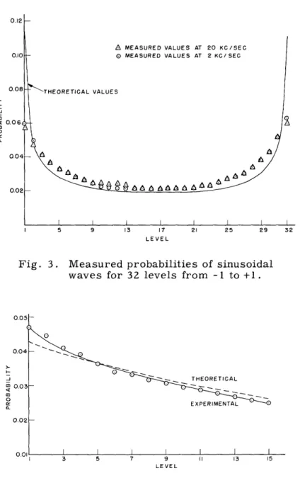
Fig. 3. Measured probabilities of sinusoidal waves for 32 levels from -1 to +1.
0.05t 0.04
o
<M 0.03a0 0.02 0.01 I I I I IG EXPERIMEI 13 15 3 5 7 9 11 13 15 LEVELFig. 4. Measured probabilities of exponential waves for 15 levels: frequency, 300 cps; R, 0.47 megohms; C, 7000 ,uf.
intensity level j. This can be seen as follows. The dwell time of the beam on square i, j is an indication of how long the picture is at level i at the same time that its displaced
version is at level j. Since the displaced version is only one cell away from the original picture, the dwell time is proportional to the joint probability p(i, j). The dwell time, though, determines the brightness at any particular point on the scope, so that the brightness of any cell i, j is in turn proportional to p(i, j). The brightness is measured by a photometer, as shown. Since 32 levels of intensity are assumed, 1024 probabilities will be measured.
The equipment is quite versatile in that probabilities of cells displaced by more than one unit shift can be measured easily. This can be done by merely shifting one trans-parency by the required amount. The measurement need not be limited to pictures. The equipment will measure the joint probability of any two signals whose highest frequency component is less than 10 Mc/sec, and whose lowest is greater than 30 cps (corresponding to the bandpass of the video amplifiers).
To check the calibration of the photometer, as well as the video amplifiers and recording oscilloscope, known probabilities of electrical waves were measured. These included both sinusoidal and exponential waves. The derivation of the theoretical proba-bilities is given in Appendix I. Fairly close agreement between the theoretical and
measured values is obtained, as Figs. 3 and 4 show. Four different repetition rates were used in the exponential-wave test: 300 cps, 1 kc/sec, 10 kc/sec, and 60 kc/sec. Only the results for 300 cps are shown, since they were typical of the curves obtained
at the other frequencies.
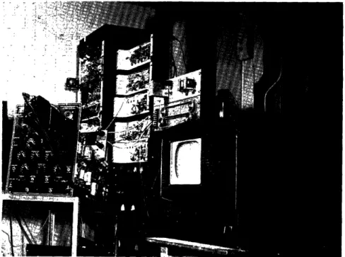
Fig. 5a. Electronic components.
..I 11z
Fig. 5b. Optical system.
The equipment is shown in Fig. 5. Figures 5(a) and 5(b) show the electronic components and optical components. Figure 5(c) is a close-up of the transparency positioning controls.
2. BOUNDING THE ENTROPY
The probabilities measured are not the true probabilities of the video signal but the probability of the signal plus noise. The main source of the noise is the original
light signal itself. This is because light travels in the form of discrete photons and generates a signal that is quite noisy. The interesting point about this noise is that it is not statistically independent of the signal. The noise and signal are linearly independent (uncorrelated), but the variance of the noise is a function of the signal. That is, the noise variance at all instants of time is different, depending on the value of the light intensity at that instant. Another source of noise is the result of thermal
emission from the photocathode of the photomultiplier, known as "dark" current. This is, however, a minor source of noise. Noise is also introduced in the photomultiplier tube because the electron stream is not continuous but flows in discrete steps. This is the familiar shot-noise effect found in the temperature-limited diode. It is also only a
minor source of noise.
At first one might be inclined to say that the noises in the two channels were not statistically independent. But this is not true. Any given photon in the original light does not know whether the beam splitter will reflect it or transmit it. Hence, the noise
in one channel in no way depends on the noise in the other, and they are thus statistically independent for any given light intensity.
Since the occurrence of noise poses a problem in that it masks the probability of the signal, some method must be used to extract the true probability. Several avenues of approach are available. Among these is the possibility of obtaining the signal proba-bilities from the measurements. The method for doing this is given in Appendix II. It is shown that given p(SI+N1; S2+N2) and p(N1; N2), it is possible to get p(S1; S2), with the assumption that the signal is independent of the noise and that the noises are inde-pendent. The last assumption we know to be true, but the first is not true. However, the simplifications obtained by making this assumption are justifiable in view of the
small error involved because of the slight correlation of noise and signal. This method, however, is very vulnerable to experimental error as we will show later. If we let F(S+N)(u), Fs(u), and FN(u) be the characteristic functions of the signal plus noise, the
signal, and the noise respectively, then (see ref. 9, Chap. III, p. 19) F (S+N)(u) = Fs(u) FN(u)
The noise is essentially "white" with a gaussian probability density. Thus FN(u) is of the form exp(-u2 ). In terms of circuit theory, this means that the signal proba-bility has been passed through a filter whose characteristic is gaussian. To get the
exp(u2), where u corresponds to . If there are any errors in F(S+N)(u), they will be enlarged by exp(u ). The most serious errors will occur at the tails of the function where u is largest. The small probabilities will then have very little meaning. For this reason, this method is only stated; not used.
It was decided to obtain two bounds for the upper bound to the entropy per symbol. One will be an upper and the other a lower bound. It is shown in Appendix III that the upper bound to the entropy per symbol H(S 2[S1) can be bounded by
H(S2 + N2
1S
1 + N1) H(Sz2 S1) Ž>H(S2 + N21S1 + N1) - H(Nz) - H(N 1)if the signal and noise are statistically independent. It is also shown that if the signal and noise are not statistically independent, the lower bound will not be affected, in that the inequality sign is just made stronger. For the upper bound, some dependence of noise on signal can be allowed. However, the inequality sign is weaker.
Schreiber (see ref. 4, pp. 36-37) used a different method for evaluating the signal entropy from the signal-plus-noise entropy. In his analysis he assumes signal and noise to be statistically independent, and also assumes the signal to have a gaussian
probability distribution. The first assumption, as we have seen, is reasonable, but the second may or may not be, depending upon what the distribution function for any particular picture looks like. However, his last assumption is not used in this analysis.
3. THE OPTICAL CORRELATOR
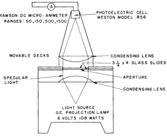
The device shown schematically in Fig. 6 is used to obtain the autocorrelation function (5) of pictures. The light source is placed at the focal point of the first con-densing lens, and thus all the light that is transmitted by the lens is composed of paral-lel rays. These rays pass through the glass slides and are collimated again by the second condensing lens onto the photoelectric cell.
TRIC CELL )DEL 856 ENSING LENS x 4 GLASS SLIDES APERTURE CONDENSING LENS
To see how the autocorrelation function is obtained, one proceeds as follows. The autocorrelation function of a function of time f(t) is defined as
] 1(T) = f(t) f(t+T)
where the bar indicates an average taken over all time for various values of the time
shift . For a picture transparency the optical transmission is a function of the vector
r, where r = r A. Hence, when one shines light through two pictures that have a relative shift Ar, one is measuring
~ll(Ar) = T(r) T(r + ar)
where Ar = ArA; and T(r ) is the optical transmission function of picture transparency. The averaging is the result of this inherent property of the photoelectric cell. The expression given above is seen to be the autocorrelation function of the picture evaluated for a vector shift Ar .
The apparatus is not limited to the measurement of autocorrelation functions but may be used to measure crosscorrelation functions by merely replacing one of the two identical slides by a different one. This is quite useful in the determination of the
Fig. 7. Optical correlator.
correlation between successive frames in either television or motion pictures. A picture of the correlator is shown in Fig. 7.
4. THE AUTOCORRELATION FUNCTION BOUND TO THE ENTROPY PER SYMBOL It is shown in Appendix IV that the normal random process with the second moments aij has the maximum entropy of all processes with the same set of second moments. Thus, by assuming a process is gaussian, one can get an upper bound to the entropy per
symbol.
The gaussian process is completely specified if its autocorrelation function is known. The entropy of the process can thus be expressed in terms of the autocorrelation func-tion. The general expression for the entropy per symbol of the multivariate normal distribution in terms of its correlation coefficients is derived in Appendix V. The bound obtained from a knowledge of the preceding sample is shown to be
H(X2 X1) = log 2re 2 + 2 log1 - 12
This bound may or may not lie between the bounds obtained by the other method, depending on the extent to which the noise affects the results. If it lies between the aforementioned bounds, it will give a tight bound to the entropy per symbol. If it does not, it will be a measure of how different the process is from a gaussian process.
An upper bound can be obtained by the use of an indefinite number of previous samples, as well as from one previous sample. The formula in this case is (see Appendix V):
1
_ _ _H(XN IXN-l' - X1 ) = 2 log 2 e
Pii l
The bound for N > 3 may conceivably be smaller than both of the bounds obtained by the probability measurement. It will certainly be less than the correlation bound
obtained for N = 2.
5. STANDARDIZATION OF TRANSPARENCIES
It is of the utmost importance that all the transparencies used in the measurements be alike. At first this may seem like a trivial problem. However, anyone who is famil-iar with photographic processes will acknowledge that it is difficult to make pictures that are alike. They may look the same to the naked eye, but compared on a densi-tometer they are very different. The differences are caused by several factors: differ-ences in photographic emulsion, differdiffer-ences in exposure time, and differdiffer-ences in devel-opment time. Any differences in the develdevel-opment process, such as the temperature of the solution and the amount of solution used, will give rise to different transparencies.
The following procedure was used to determine whether or not the transparencies were similar. A diffuse density step tablet was printed on the 35-mm and 4 X 3 1/4 glass slides. This tablet consisted of a negative whose optical transmittance varied in steps along its length. We measured the transmittance of each step on each transpar-ency and determined whether they were the same or differed by a constant multiplier. Only transparencies which satisfied these conditions were used in the measurements. This amounted to making certain that the gamma (see ref. 10, pp. 195-201) of the pictures was the same.
The quantity y is defined as aD
Y a(log1 0E)
where D is the density, the ratio of incident to reflected light, and E is the exposure of any given point on film.
If y is unity, a picture which is directly proportional to the original has been made. However, if y is not unity, then one has a picture that corresponds to the original signal raised to the power y. Thus it is seen that unity gamma, or a gamma which is the same for all transparencies, is essential.
IV. COMPUTATIONS AND RESULTS
1. THE JOINT PROBABILITY MEASUREMENT
Since it is of the utmost importance that the gamma be unity, or the same for both transparencies, the first step in the experimental procedure is to measure the gamma and make certain that either one of these conditions holds. This is done by masking the transparency except for the step tablet. The pattern is then scanned vertically. That is to say, the step tablet is scanned from its densest step to its lightest step as the flying-spot scanner beam travels downward. The resultant video waveform is then viewed on an oscilloscope, and the steps in intensity are observed. When these steps
are the same or differ by a constant multiplier for a pair of transparencies, one can be sure that the transparencies are suitable for the measurement.
The masking is then removed from the picture portion of the glass slide and the step wedge is so masked that it does not interfere with the measurements. The transpar-encies are put into their holders and positioned until they are in register. A sensitive indication of this condition is a complete void on the picture monitor. The transpar-encies are then shifted from register by a one-cell displacement. Since for equal verti-cal and horizontal resolutions there are 700 cells in a horizontal line, and since the picture is 1 1/3-inches wide, one slide is shifted 0.00190 inch past the other. The brightness pattern on the face of the recording oscilloscope is divided into 1024 cells, and the brightness of each cell is measured. This measurement is repeated three times and the results are averaged. The data obtained with the photometer are in arbitrary units and are linearly related to the logarithm of the corresponding probability. To convert this reading to actual brightness, we use the equation
D = 1 03(1-R)
where D are the data proportional to brightness and thus to probability, and R is the reading taken with the photometer.
This conversion equation is a consequence of the manner in which the photometer was calibrated.
The number recorded in the it h row and jth column is called D(i; j) and is propor-tional to the corresponding probability, p(i; j). The calculation of the conditional entropy from these values is performed as follows: since
Z
p(i;j)= 1
i,j D(i; j) D(i; j) p(i; j) = = E D(i; j) k i,jThe conditional entropy is p(i; j) H(YIX) = - p(i; j) log
p(i) where p(i) = p(i;j)
J
D(i; j) kH(YIX) = -Z p(i;j) log p(i;j) + p(i) log p(i)
ij i
The complete procedure can be summarized as follows:
1. Add each column to obtain a column sum, and then add the column sums; this total sum yields the constant k.
2. Divide each D(i; j) by k to obtain p(i; j). 3. Divide each column sum by k to obtain p(i).
4. From an entropy table obtain (-p log p) for each p(i; j) and p(i) (see ref. 11). 5. Sum all terms of the form -p(i; j) log p(i; j).
6. Sum all terms of the form -p(i) log p(i).
7. Subtract 6 from 5 to obtain the conditional entropy.
As we mentioned previously, this conditional entropy is not the true entropy
H(S21S1), but is H(S + N2IS1 + N1). It is proved in Appendix III that the latter entropy forms an upper bound to the former entropy. To obtain the lower bound, the entropies of the noises are required. Since the actual noise entropy is difficult to obtain, one must calculate an entropy that is always greater than the noise entropy. The procedure is as follows: The variance of the noise is
2 - 2
2= (N-N)2 = (N-N) p(N; S) dNdS
N S
=
S p(S)dS N (N-N)2 p(N IS) dNS N
The second integral given above represents the noise variance for a given value of signal 2
and is designated by -S .
Since the instantaneous noise power is directly proportional to the instantaneous
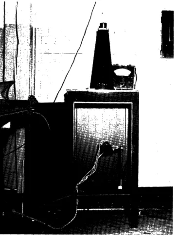
o BEAM = 56fA A I BEAM = 43p.A
A I BEAM = 26A 0 IBEAM = 15 A
LEVEL
Fig. 8. Conditional noise probabilities (dashed lines designate value of mean).
0 . I I I I !1I I I =I M a. 0.6 -j 0.5 0.4 ,o z 0.3 20 0 0.2 0 8 16 24 32 40 48 56 64
BEAM CURRENT (A)
signal, 0rS will be proportional to the instantaneous signal. Thus
r = S p(S)dS = k Sp(S)dS ,S
= kS
Hence, the variance of the noise is the variance that will occur at the mean of the signal. Now that the variance is known, an upper limit to the noise entropy can be set by assuming that its probability density is gaussian (see Appendix IV). The entropy of a first-order gaussian process is (see Appendix V)
1 2
H = log 2re0
Thus if -2 is known, the entropy can be calculated.
To check the fact that noise variance goes down with signal, and thus with beam current, probabilities of noise for various beam currents were measured, and the vari-ances computed were plotted against the beam current. The results are shown in Figs. 8 and 9. Figure 9 shows that a linear trend appears.
The smooth curves through the discrete probabilities of Fig. 8 have no real meaning. They were drawn to look gaussian with the same variance as the discrete probabilities and centered on the same mean. The entropies of the discrete and continuous distri-butions were calculated, and it was found that they differed at most by 5 per cent. Thus, very little error is incurred by assuming the noise is continuous. This is undoubtedly
due to the fact that entropy is a slow function of the shape of probability distributions and depends more on variance. As a matter of fact, it is likely that very little error
in entropy is incurred by assuming the noise has a gaussian distribution for the same reason.
In the lower bound
H(S2 S 1) H(S Z + NH2S 1 + N1) - H(N1) - H(N2) H(N1) = H(N2)
since the noises have the same statistics. The lower bound becomes H(SzIS1)> H(S + N+ N 1 N1)- log 2e 2
The complete procedure follows.
1. From the previously computed values for p(i), determine the mean value of i, denoted by i.
2. With this mean value of signal, and thus beam current, pick off the variance of the noise from the graph of Fig. 9.
3. Insert this quantity in the inequality given above to derive the lower bound to the entropy.
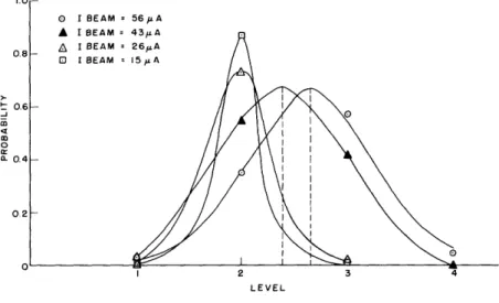
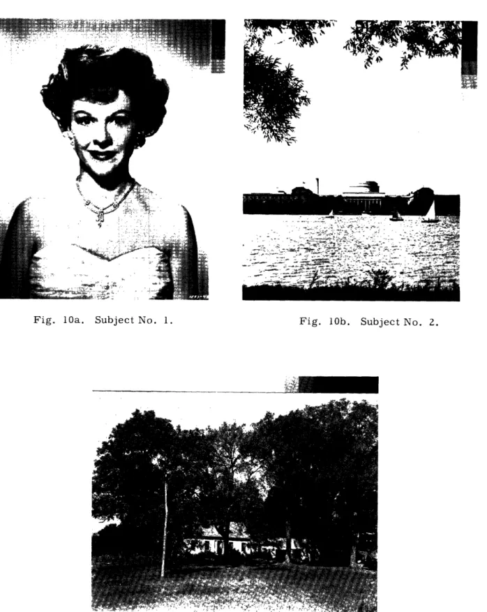
Fig. 10b. Subject No. 2.
Fig. 10c. Subject No. 3.
24 ROMMEMOSIENCEFUG7,~` *, ---- .
-1---
A&L:. 11( I "'g . .. 1 *" ... i;- L-~
IFig. 10a. Subject No. 1.
71~~7,,w
~
,~-
Fig. 10d. Subject No. 4.
Fig. 10e. Subject No. 5.
25
I
The experimental and computational procedure is now complete. The results are given in Table II. The five subjects mentioned in this table are shown in Figs. 10(a)-10(e); their data sheets are given in Figs. 11(a)-ll(e).
Table II.
Computed Upper and Lower Bounds to Entropy per Symbol Subject Upper Bound (bits) Lower Bound (bits)
1 1.365 0.6725
2 2.075 1.450
3 0.982 0.357
4 1.696 0.976
5 0.758 0.713
2. THE AUTOCORRELATION FUNCTION MEASUREMENT
In this measurement, not only is it essential that the glass slides have the same gamma, but that they have the same gamma as the 35-mm transparencies of the previ-ous measurement. The gamma of the 3 1/4 x 4 transparencies is measured by masking everything but the step tablet and measuring the light transmitted by each step. When two slides have the same set of readings as obtained previously for the 35-mm trans-parencies, they are suitable for measurement. It is significant to note that the gamma is measured in a manner that is different from the previous measurement. This is as it should be, since what is essential is to reproduce the actual conditions under which the experiment is performed.
It is important that the area of the aperture remain constant as the slides are shifted relative to each other. Since a total shift of 0.5 inch is to be used, a 0.25-inch strip along each edge of the aperture is masked off, so that as one transparency is moved the aperture area will stay the same. The two slides are then put in their holders and posi-tioned in register. This condition is indicated by a maximum of transmitted light and thus a maximum in the meter reading. One slide is shifted horizontally by an amount AS. The reading corresponding to this is the autocorrelation function for a shift of AS. This is repeated several times until a relative shift of 0.5 inch is obtained. The pro-cedure is repeated for vertical shifts. A contour of constant autocorrelation is then obtained at a convenient value between zero and a 0.5-inch shift.
Since it is the correlation coefficient that is of interest, it must be calculated from the measurements. It is defined as
Cd -r) o Qo ~ C)~~~~~~~~~~~~~~~~~~~~~~~~~~~C oN -Cd r-~~~~~~~~~~~~~~ -- 0 cJi
~~~nl~ ~~o
o ,. -Cd -I- i ~~~~~~~~~~~~~~~~~~~~~~~~~~~~~--Cd -OD co - - -1
o10
00 _~~~~~~~~~~~~~~~~~~~~~~~~~~~~~~~~~~~~~~~~~~~~~~~~~~~~~~~~~~~~~~~~-o0 ( N~~~~~~
- *D r m~~a)C -- O~l0 ,- - a. ()o
~
-
~
~
-
-o~oN - - - -d …_o~· oola~
~~~~~~D~~~~
N13~
oo o-.rmm
~~~~~(
oo oi~~~~~~l~~~l~~l~~~o r~
~
~
~
1 J:~- ·~hl
Cd _______ _______ _______ _______I
9~~~~~~~~~~~~~~~~~~~~~~~ /N~ . cQ 0 O (0 It C 0 o re Cdl cd Cd cd c CO (0 I c 0 Oa (o - Cd 27
7-
--I --I
N - LI ! 'lI- In . 1N N i N _I
-I N 0 Oa (N 4 C N 0O K) r') CM C\0 C04 04 04J ro O0 co Q cl c o CD ct d Co oD U CC co -NL
-
:--
--
- l-I:
-- IL L
E
Z
E
l IE
I
---7 -7_17
j
I
-I
1
---I
-1
-7I
I I n I I I 11 I I 1 I II 1 I ZI I 11 I 1 I II I I 1 I 1 I "I I I 4 I I II I I 2 I I I I I 1 I I I I 1 II I II 1 n I 1I 2 1 2 I I II 11I 11 I I It I
h-
t
I
1i
l1 L---IL-I
i ---1 -I -I I -11 \ I Ii IIIO \D 2 III I.1 ID I I r Iid I 1 I 1 2 1 n I I II II I 2I 1 II II 2 2 I 1 I I I II I II I II I I 9 rt
t
-I I Im I I I -\D I l II II 1C I I II II I Iu I INIi7-I
I
-- lF-LL
i
r--,1-1
II 'Il _: I I I 1m I 2 -1 9 f I 1N mE
C~4C-
_ m IN rq, i 9 I _-_-i
:L
I
.I
2 .1 It 6 O < N _ _' r _ D_
|N _-0 O (0 q d T T c i j0 0 In 9 O 0 0 nio pl-IN 9 3 O d10oo I o ao Nm dl·IQiaO · in, o 0 m -· 31 rs OI ·IcO 0 -rid m -imle mimi3 C Oi\D 9 COIP rn 01·1·10 m iOi·13 I- m mim 0 mllr- m oio1·l1u, O"N N m -i-·I s · -· ,,"" mim N lli d131
rt7
m N O )·I OOiT- · m N 3irn ml-it 3 n m N m \D1Clm J) N C ----ru I-I-m ln O\IN inlml-im Ni31rn u, m N \01 i Im 3 m o·I·iclN 9 m m 0 · I hi -sm-d o oim -19 ru N N llin m m 9 N m m N N 31·lg1 C rn 9N m s 0 hlli
3lml3 m iibOI 0· Nlm \o oi·ll"lmlldOl·l·IN 9 b\ON 9 1131 3 N 01 9 - mIP- OIN d i ·ICII 'IN 3-rlm t-N 9 -$1· N 61-3 m in dfdrnDil 1N \t) " I rcoo-r·ou, nl NISINI\D InNIO' 3\06 CN O o (D t C O n r) C\N N N N C\ (D q cN O a) (D c3 N CM 0 C) -4 0 ND U ci o cooPPq (0 -bn N'
01"1
N N
rll mlru r- lm o·i-i NIN Nl'limlOlvl hliml31NI-0· 3 1·101 IOIC mim IN · 0 0 3 0 010 V1 rt 00 mllrn 1010 010· IN13 1- m o 010 s "8,'-N ml-l-IN1-1 a lol ol-·lo Imim oor-Fllmlnl-
ii-c·rlm(o( i·olc N8mrc ru in NIco ollo ml·1019 uilolnlio -P mim ol·D JN/·I·lm m10 Ln rnIIlIlIlI NCCONm \O ln1310` r--il OLlmim " Dlrc a rO IO mui·ii m - U11 -1- 9 0 N IC 91' " P· OINI-IOo N 0 0\ 0 d -19 d·DP-m orn3 N m I ols -· - \o r-IN OIIN 3 N Ill'liNllm a N IIIC m m in ol- rro r-N-·mhl c in 1110 0 0 \D0 olo r- 1-NIL3(/1-0 Ln Niilim N m 0 OiT- d rlcl a, edl3lm 0· N 10 N1'1 miNI·l·l -lmiN -0 NI -·I dl-lmi·-lrn n 0 ol-o mlhll Iln i -imimici m lrc a 0 co N Nn 13 IN Vllr0110·IN Nlnl·lo0 N In ml-l aioiuio 11i1-31i CJ 0 N (0 N cJ ra) VI oj Cj Cj clJ 0 O 0 ' c 0o OD (D 0- C' c'J 0 C\I O C-) , 0 c\J -Z Y) o = c - 0-on oU) blaD bDa c rn c-Irr~~~~~~~~
I
I
O
I
I-
oD~~~~~~~~~~~~~~~ NINI-~ ~ ~ ~ ~
_ c 0 ( ~ 09 N c 0 rr) rY) Nl N NU NO c a, (O I N 0 O (0 . Nl 0 OD C o. o . cU C_ U-N Cr 0 - o N a, O (D _ 1 4 1t a Nwhere x1 is the mean transmittance of the first transparency and x2 is the mean
trans-mittance of the second transparency.
As the slides are shifted, substantial amounts of new picture material are introduced into the aperture. Thus the mean transmittance of each transparency will not be con-stant. Additional measurements have to be made to determine this "floating" mean. This is done as follows:
T I(F)Ti (0)
p(A-F) = kT 2(Ai) - T
where T is the transmission with both slides removed, T2(AF ) is the transmission
through the two cascaded slides shifted by aF, and Tl(aF) is the transmission of a
sin-gle slide with the same displacement ar.
To obtain the normalized correlation coefficient, division by the variance is neces-sary. It is given by
2 = k (T2(0) - 1T
The normalized correlation coefficient is given by
p(AF) TT 2(AF) - T(AT) TI(0)
2 TT 2 (0) - T (0)
Figures 12 and 13 are plots of the normalized correlation coefficient versus Ar- for horizontal and vertical shifts, respectively. Figure 14 shows contours of constant normalized correlation coefficient for the five subjects.
It is shown in Appendix V that the conditional entropy is
H(YIX) = log 2recr2 + log 1 _
(12
The quantity (P1 2/0-2 ) is the value of the normalized correlation coefficient for a unit
2
shift in the horizontal direction. The only quantity which is not known is a. . It is found as follows:
2 T Z(o) T (o )) (32)
Thirty-two levels from black to white are assumed. This presupposes that the intensity range of all subjects is the same. This, however, is not a true assumption, since it was found that not all the transparencies had the same intensity range. It was assumed that Subject No. 1 covered the entire range from black to white, and the variance of the other transparencies was adjusted to take into account the difference in intensity ranges. In the continuous case the entropy can be considered a measure of randomness relative
Fig. 1i
-0.25 - 0.20 -0.15 -0.10 -0.05 0 0.05 0.10 0.15 0.20 0.25
HORIZONTAL SHIFT A 7-(INCHES)
40 20 0 20 40
HORIZONTAL SHIFT A (NUMBER OF PICTURE ELEMENTS)
2. Normalized correlation coefficient versus Ar for horizontal
VERTICAL SHIFT A r"(INCHES)
I I I I I
40 20 0 20 40
VERTICAL SHIFT A -(NUMBER OF PICTURE ELEMENTS )
Fig. 13. Normalized correlation coefficient versus Ar for vertical
shifts.
shifts.
-0.06
2 0.745
-0.06
Fig. 14a. Isonormalized correlation coefficient contour for subject No. 1.
0 -0.32 -0.24 -0.16 -0.08 0O .24 G _-O Yz 0.16 t -0.08 O 0.08 0.16 0.'4 HORIZONTAL SHIFT (INCHES
-0.08
-0.16
-0.24
Fig. 14b. Isonormalized correlation coefficient contour for subject No. 2.
-I
I I l I -0.16 -0.2 -0.08 -0.04 0.08 I \ -L P 0,.664 - 2 I 0.04 >1 I I r 0.04 0.08 0.12 HORIZONTAL SHIFT (INCHES)-004
-0.08
-0.12
Fig. 14c. Isonormalized correlation coefficient contour for subject No. 3. 0.753
1
0.32
006
P 075
-~ 0.75
Fig. 14d. Isonormalized correlation coefficient contour for subject No. 4.
Fig. 14e. Isonormalized correlation coefficient contour for subject No. 5.
to an assumed standard only. Thus, to enable us to compare these results with those of the previous experiment, Subject No. 1 was taken as the standard.
This determines all quantities in the expression for H(YIX), and it may be computed. The results are given in Table III.
Table III.
Computed Autocorrelation Bound to Entropy per Symbol
Subject Conditional Entropy (bits)
1 1.340 2 1.605 3 1.930 4 2.350 5 2.810 3. ACCURACY OF MEASUREMENTS
It is appropriate at this point to consider the various sources of error that are intro-duced in the experiment. The joint probability measurement will be considered first.
A primary source of error in this measurement is the phosphor of the flying-spot scanner tube. It has been assumed throughout that the luminosity is the same for all points on the phosphor. This, however, is not true, as we can see if a blank pattern is being scanned. The recording oscilloscope pattern in this case is oblong and ellip-tical in shape instead of being just a small circle. It is observed that the variation in luminosity of the phosphor is approximately 10 per cent. That is, the ratio of the differ-ence of the maximum and minimum light to maximum light is 10 per cent. This is equivalent to a spread of three cells. This nonuniformity has the effect of changing the picture. The effect is not too bad, however, since on the monitor the picture looks very
much like the original.
Lack of precision in reading brightness from the face of the recording oscilloscope is another source of error. Since the maximum error incurred by the photometer itself is only 5 per cent, it may be disregarded as a serious source of error. Random move-ment of the pattern on the recording oscilloscope also leads to errors. If the brightness of the recording oscilloscope were to change erroneously, an error would result.
The amount by which the pattern is positioned is determined by precision resistors that are accurate to 1 per cent. However, if for some reason the pattern were not positioned correctly, an error would result. Because of the small size of the aperture used in the photometer, any small shift in the pattern will lead to an appreciable error.
Finally, if the gammas of the transparencies were not the same, the results would be in error. In this case, one would be measuring the statistics of two pictures, one of which is the equivalent of the other raised to a power. The value of the exponent
would be proportional to the difference between the gamma of each transparency. In the autocorrelation function measurement, the main source of error is the bulb. The light output of the bulb is not constant for long periods of time and has a tendency to drift. This is no doubt caused by variations in filament temperature. The photocell
and microammeter do not introduce appreciable error when used properly. The photo-cell must be loaded by a constant resistance for the microammeter readings to have relative value. Thus, as the scale on the microammeter is changed, an external resist-ance is added to keep the load on the photocell constant.
V. ANALYSIS OF RESULTS
The joint probabilities measured are conditional in that they are measured for a particular picture. To get the actual joint probabilities, measurements must be made on an infinite number of pictures and the results averaged over this ensemble. The impracticability of this course is evident. What we actually do is to choose subjects having little to great detail. An average entropy is then obtained by assuming that each picture is representative of its set and thus occurs with probability one-fifth. This value is different from the entropy calculated from the averaged joint probabilities. The difference between the two will depend on how different the probabilities of the specific pictures are from the probabilities of the average picture. From the viewpoint of coding, the average entropy corresponds to coding all types of pictures, whereas the entropy of the average indicates a system in which the coding scheme is designed for average pictures. The choice between the two is determined only by the flexibility desired in the coding system.
From the probability measurement the average upper bound is 1 .375 bits while the average lower bound is 0.834 bits. For present-day television, where equiprobable events are assumed, the entropy for a 32-level system would be log 32 or 5 bits. Thus, approximately 4 bits of redundancy are exposed. This means a potential reduction, by a factor of three to five, in the channel capacity required for television transmission. This reduction can be brought about only by means of an ideal coding scheme. As we mentioned previously, this reduction can be effected as a saving in either signal power or bandwidth, or both.
It is of interest to note that some of the more detailed pictures did not have a greater entropy than the less detailed pictures. In particular, Subjects No. 3 and No. 5 had less entropy than Subject No. 1. This is contrary to one's expectations, judging from a subjective estimate of the order of complexity of the pictures. However, one must also keep in mind the intensity range covered by each transparency. If there is great detail in a picture at low contrast, the picture contains little information. If a picture of a black dog in a coalbin at midnight is taken, there will be great detail but practically no information in the picture, as it will be nearly all black. However, if the same pic-ture is taken with a flash attachment, then it will contain much information. We see how the information in a scene depends not only on the detail but the intensity range covered by the scene. This fact would have to be taken into account in the coding scheme used. Thus, one can either define an intensity range from white to black for all pictures and keep the gain constant, or vary the gain so that all pictures will cover the same equiva-lent intensity range. This second scheme is used in present-day television transmis-sion. The black level is set at 75 per cent of the maximum amplitude of the carrier envelope. The gain is then adjusted so that the white portion of the picture has an amplitude which is approximately 15 per cent of the maximum amplitude of the carrier envelope. In the final analysis, the appearance of the picture is determined by how the