DOI 10.12900/RBM14.20.2-0007
Investigations into the Water Repellent Surface Near Layer in Concrete
by Neutron Radiography
P. Zhang1, F. H. Wittmann1,2*, T. J. Zhao1 and E. H. Lehmann3
1Qingdao Technological University, Qingdao, China 2Aedificat Institute Freiburg, Freiburg, Germany 3Paul-Scherrer-Institut, Villigen, Switzerland
*Corresponding author: F. H. Wittmann, e-mail: wittmann@aedificat.de
Abstract
By impregnation of concrete with a water repellent compound such as silane, a water repellent surface layer can be established. Due to this surface impregnation capillary absorption of water and aqueous salt solutions can be significantly reduced. The aim of this protective surface treatment is in many cases to obtain better frost resistance and to reduce chloride penetration. Water vapor can still transgress the impregnated layer in and out of concrete. In this contribution experimental results to visualize the width and the water content within the water repellent surface layer are described. The water distribution was determined quantitatively by neutron radiography. The results obtained allow us to explain earlier findings, which indicated that an effi-cient chloride barrier can be established by deep impregnation only. In a water repellent layer with a thickness lower than 6 mm there remains enough water which allows reduced migration of chloride into the pore space of the material. The requirements of published recommendations are herewith supported and justified.
1
Introduction
Carbonation and chloride penetration into rein-forced concrete are often the main reason for nec-essary early repair measures and too short service life of buildings and structures. Chloride is in many cases transported into the pore space of con-crete by convection when salt solutions, such as seawater or water contaminated with deicing salt, are absorbed by capillary action. Once the chloride is transported into the pore space of concrete by quick capillary action it may further migrate slowly by diffusion to reach finally the steel rein-forcement. If a critical concentration of chloride is reached in the region around the steel reinforce-ment, corrosion may start. If the surface of con-crete is impregnated with a water repellent sub-stance such as linseed oil or silane, capillary absorption may become negligible. In practice it has been observed quite often, however, that chlo-ride penetrated into surface impregnated concrete, although with reduced rate.
If a very thin surface layer is impregnated only, the water repellent effect may be obvious during visual inspection of a surface when water is splashed on it. But in practice in most cases an aqueous salt solu-tion is in contact with the concrete surface for longer periods, may be days or even weeks. Exper-imental results have shown that a minimum thick-ness of the water repellent surface layer must be achieved to make sure that chloride cannot enter the pore space.
In this contribution the thickness of different water repellent layers shall be determined quantitatively by means of neutron radiography. If it can be proved that in thin water repellent layers there is still some liquid water available, chloride ions may migrate through the layer by diffusion, passing through still existing water bridges. In this case chloride penetration may be slowed down but it will not be prevented. It should also be studied, which minimum thickness of the water repellent layer is necessary to act as a real chloride barrier. Based on these data requirements for an efficient chloride barrier can be formulated or verified and reliable recommendations for practical applications can be formulated. This may be considered to be a reliable basis for quality control.
2
Experimental
2.1 Preparation of Mortar Specimens
In order to study the specific properties of a water repellent surface near zone in cement-based mate-rials, mortar cubes with an edge length of 100 mm have been produced in steel forms. The water-cement ratio of the mortar for these test series was chosen to be 0.6. Details of the compo-sition of the mortar are given in Table 1. Ordinary Portland cement type 42.5 and river sand with a maximum grain size of 2.5 mm were used. The fresh mortar was covered with a plastic sheet after compaction and stored in the workshop for 24 hours. Then the steel forms were removed and the concrete cubes were stored in a humid room with RH
≥
95 % and T = 20 ± 2 °C until they have reached an age of 28 days. The hardened mortar cubes were then cut into slices with a thickness of approximately 20 mm with a diamond saw. The slices with dimensions of 20 x 100 x 100 mm were further stored in the laboratory atmosphere, which has a relative humidity of approximately 60 % and a room temperature of approximately 20 °C, for one week. Then the mortar slices were ready for impregnation with silane gel, i. e. liquid silane stiffened by addition of fine clay particles.2.2 Surface Impregnation
The surface of the mortar slices, which was in con-tact with the bottom of the steel forms during cast-ing, was selected for impregnation. This represents a formed surface in contrast to a finished surface. This formed surface was impregnated with silane gel (StoCryl HG200). Three different amounts of silane gel were carefully spread equally over the surface: 100 g/m2, 400 g/m2 and 600 g/m2. The differently treated samples were labeled with G100, G400 and G600. All three types of impreg-nated mortar specimens were then stored for four more weeks in the laboratory atmosphere to allow the penetrated silane to react fully to form a silicon resin film on the inner surface of the mortar and to reach hygral equilibrium with the laboratory atmosphere. By gravimetry it was checked if hygral equilibrium was achieved.
Table 1: Composition of the mortar, the mass of
cement, sand and water is given as kg/m3.
2.3 Neutron Radiography
Water repellent mortar specimens and untreated companion mortar specimens were then tested in the neutron radiographic facilities NEUTRA at Paul-Scherrer-Institute (PSI) in Villigen, Switzer-land. The diameter of the neutron beam was 400 mm and the collimation ratio was 550. The neutron flux during the tests was 5.1 x 106 cm-2s-1mA-1. More details on neutron radiography are described in the literature [1-3]. First, neutron images were taken on samples, which were in hygral equilibrium with the room atmosphere (RH
≈
60 %; T≈
20 °C). Then silane impregnated and untreated samples were placed in water for three days. This period was sufficient to have the samples completely water saturated by capillary absorption. Neutron images were first taken from mortar specimens, which were in hygral equilib-rium with the laboratory atmosphere (air dry). Then neutron images were taken from water satu-rated samples. Both, untreated and surface impreg-nated mortar samples in the water saturated state were investigated. From the neutron images the moisture distribution can be determined quantita-tively.3
Results and Discussion
3.1 Neutron Transmission
Neutron images of the three types of impregnated and water saturated mortar specimens are shown in Fig. 1. As the upper impregnated surface is of interest exclusively in this context, the upper half of the neutron images is shown in Fig. 1 only. It can be clearly seen with the naked eye that the neu-tron transmission is significantly higher in the outer impregnated layer. The thickness of the impregnated layer can be estimated already from
the results shown in Fig. 1. The following average values of the thickness of the impregnated layer have been determined by visual inspection 2.0, 4.1, and 6.3 mm for samples G100, G400, and G600 respectively.
The darker area in Fig. 2 represents the surface near zone, which is impregnated with silicon resin. Enough hydrogen is fixed in silicon resin in OH-groups and CH-groups and this hydrogen is at the origin of scattering neutrons out of the neutron beam. This process leads to the darker surface zone, which can be observed in Fig. 2. The thickness of this zone corresponds to the thickness of the zone with reduced water content shown in Fig. 1. The technology to visualize the silicon resin films opens up new possibilities and it will be further developed in the future.
The neutron transmission of untreated and silane impregnated mortar specimens has been deter-mined quantitatively. In Fig. 3 the transmission pro-files as obtained on untreated specimens stored in the laboratory atmosphere and on water saturated samples are shown. As expected the neutron absorption of the water saturated specimens is much higher. The difference between the two lines shown in Fig. 2 is approximately constant, that means samples are homogeneously filled with water. In this case the water content of the air dry samples was 6.5 Vol. % and the water content of the saturated samples was 18.4 Vol. %. As a conse-quence the distance between the two lines in Fig. 3 represents a homogeneous water content of 11.9 Vol. %. From these data we can calculate that in the hydration products of the dry mortar there is approximately 4.1 Vol. % of water chemically bound.
Figure 1: Neutron images as obtained on the three types of water repellent surface impregnated and water saturated mortar specimens. The upper half of the neutron images taken on square slabs is shown only.
The neutron transmission as determined on the three surface impregnated specimens G100, G400 and G600 are shown in Fig. 4. The transition of samples G100 in the bulk of the specimens is nearly constant but close to the impregnated surface trans-mission goes up. The influence of the silane impregnation in samples G100 can be observed until a depth of approximately 2 mm. In the air dried specimen there is less water in the surface near zone. That means that a certain part of the pores which are filled by capillary condensation in untreated specimens are empty after water repellent treatment, because the walls of these pores are cov-ered by a silicon resin film. Finer pores still contain
capillary condensed water under the environmental relative humidity. It is quite obvious that the influ-ence of the reduced water content on neutron trans-mission is much stronger than the influence of the silicon resin. Nevertheless for a quantitative analy-sis the contribution of the silicon resin has to be taken into consideration.
Figure 2: Neutron image of an air dry specimen after impregnation with 600 g/m2 of silane gel (G600). In this case the silicon resin in the impregnated zone can be visualized.
Figure 3: Neutron transmission as function of the dis-tance from the surface, measured on untreated water saturated and untreated room dry samples.
0 0.1 0.2 0.3 0.4 0.5 0 4 8 12 16 Depth, mm T h e t ransm issi on val ue Untreated_room dried Untreated_water saturated 0 0.1 0.2 0.3 0.4 0.5 0 4 8 12 16 Depth, mm Th e t ra n sm is si o n va lu e G100_room dried G100_water saturated 0 0.1 0.2 0.3 0.4 0.5 0 4 8 12 16 Depth, mm Th e t rans m is si on va lu e G400_room dried G400_water saturated 0 0.1 0.2 0.3 0.4 0.5 The t rans m issi o n val ue G600_room dried G600_water saturated
The situation in samples G400 is similar but the influence of the water repellent layer reaches obvi-ously deeper into the material, that means silane has penetrated deeper into the pore space. As expected the water content of the G600 specimens is strongly reduced in a surface near layer with a thickness of approximately 6 mm. There is a small difference only between the transmission of the room dry and the water saturated specimens in the surface near impregnated zone. In specimens G600 the water content in the water saturated state approaches the water content of the room dried samples. Nearly no water has been taken up by capillary absorption. This situation can be considered to be a necessary requirement for the establishment of a reliable chlo-ride barrier.
3.2 Water Distribution
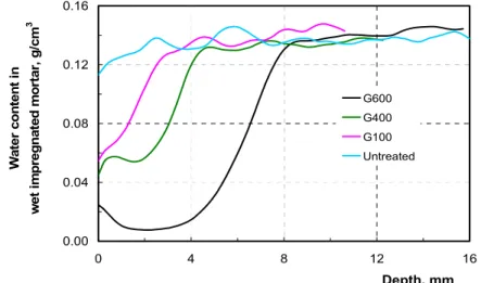
The water distribution was calculated in the sur-face near zone as indicated with the rectangular frame shown in Fig. 1 (G600) from the neutron images obtained from water saturated specimens. Results are shown in Fig. 5. As expected the mois-ture content in the untreated specimen is essen-tially homogeneously distributed all over the vol-ume. The observed slight decrease of water content close to the surface may be attributed to a small water loss during handling before taking the first neutron image.
On the surface impregnated specimens, however, the influence of the water repellent surface near zone can be observed clearly. As expected, the water content in the water repellent zone is
signifi-cantly reduced. The width of the water repellent zone can also be observed quite clearly. In samples G100 a water repellent layer with a thickness of approximately 2 mm has been established. In sam-ples G400 and G600 the thickness of the water repellent zone can be estimated to be approximately 4 and 6 mm respectively. What is most important, however, is the fact that in samples G100 and G400 the water content in the water repellent zone is cer-tainly substantially reduced but still a certain amount of water can be observed in this region. In contrast in samples G600 a minimum amount of water can be detected only. From these results it can again be concluded that deep impregnation as in specimens G600 is necessary for an efficient chlo-ride barrier. The remaining water in the impreg-nated specimens G100 and G400 may still transport a certain amount of dissolved chloride ions. This observation is in good agreement with results of tests to check the efficiency of surface impregna-tion with respect to chloride penetraimpregna-tion. If the water repellent zone is not thick enough the rate of chloride penetration is reduced but it is not zero. To establish a real chloride barrier a water repellent zone as established in specimens type G600 is nec-essary [4]. The remaining water in samples type G100 and G400 is sufficient to transport a reduced amount of chloride through the barrier. Chloride penetration is slowed down but not prevented. For this reason deep impregnation is required according to recommendations [5-9] if an effective chloride barrier is to be established in concrete.
Figure 5: Water content in surface impregnated and water saturated mortar specimens G100, G400 and G600. For comparison the water distribution in untreated mortar is also shown.
0.00 0.04 0.08 0.12 0.16 0 4 8 12 16 Depth, mm Wa te r c o n te n t in w e t im p re g nat ed m o rt a r, g/ c m 3 G600 G400 G100 Untreated
4
Conclusions
Based on the results presented in this contribution it can be concluded that:
(1) Water repellent surface layers with a thickness below 5 mm still contain a certain amount of water if placed in direct contact with water. Chloride can be transported through the still existing water bridges. Chloride ingress into the pore space is slowed down but not prevented.
(2) To prevent chloride penetration into concrete, deep impregnation with silane is necessary. A min-imum thickness of the water repellent surface layer of 6 mm must be achieved.
(3) After water repellent surface treatment a strict quality control must make sure that the minimum thickness of the water repellent layer has been achieved.
Acknowledgment
The authors gratefully mention that STO, Ger-many, has provided them with silane gel. In addi-tion the authors gratefully acknowledge the sub-stantial support of ongoing projects by National Natural Science Foundation of China (nos. 51278260 and 51008165), Collaborative Innova-tion Center of Engineering ConstrucInnova-tion and Safety in Shandong Blue Economic Zone and National Basic Research Program of China (no. 2009CB623203).
References
1. H. Pleinert, Determination of Moisture
Dis-tributions in Porous Building Materials – Neutron Signal Transfer Analysis, Building
Materials Reports No. 10, Aedificatio Pub-lishers Freiburg (1998).
2. H. Pleinert, H. Sadouki and F. H. Wittmann,
Determination of Moisture Distributions in Porous Building Materials by Neutron Transmission Analysis, Materials and
Struc-tures 31 (1998) 218-224.
3. F. H. Wittmann, P. Zhang and T. Zhao,
Dam-age of Concrete under Combined Actions,
Restoration of Buildings and Monuments, 17 (2011) 321-330.
4. H. Zhan, F. H. Wittmann and T. Zhao, Relation
5. S. J. Meier and F. H. Wittmann, Water
Repel-lent Surface Impregnation of Concrete: Guidelines and Recommendations, in Basic
Research on Concrete and Applications, Proc. ASMES Int. Workshop, F. H. Witt-mann and O. Mercier, editors, Aedificatio Publishers Freiburg, Germany (2011) 49-66. 6. S. J. Meier and F. H. Wittmann,
Hydropho-bieren von Betonoberflächen – Empfehlun-gen für Planung und Applikation; Traitement hydrofuge de la surface des structures en béton – Recommendations pour la planifica-tion et l’execuplanifica-tion, Swiss Federal Office for
Roads, ASTRA Report No. 591 (2005). 7. S. J. Meier, Grundlagen und Möglichkeiten
einer Hydrophobierung von Betonbauteilen,
Building Materials Reports No. 21, Aedifi-catio Publishers Freiburg (2003).
8. A. Gerdes and F. H. Wittmann,
Hydropho-bieren von Stahlbeton, Teil 1: Transport und chemische Reaktionen silicium-organischer Verbindungen in der Betonrandzone,
Resto-ration of Buildings and Monuments 9 (2003) 41-64.
9. A. Gerdes and F. H. Wittmann,
Hydropho-bieren von Stahlbeton, Teil 2: Ausführung einer Hydrophobierung – Voruntersuchung, Durchführung und Qualitätssicherung,
Res-toration of Buildings and Monuments 9 (2003) 117-138.