ﺔﻴﻁﺍﺭﻗﻭﻤﻴﺩﻟﺍ ﺔﻴﺭﺌﺍﺯﺠﻟﺍ ﺔﻴﺭﻭﻬﻤﺠﻟﺍ
ﺔﻴﺒﻌﺸﻟﺍ
ﻲﻤﻠﻌﻟﺍ ﺙﺤﺒﻟﺍ ﻭ ﻲﻟﺎﻌﻟﺍ ﻡﻴﻠﻌﺘﻟﺍ ﺓﺭﺍﺯﻭ People’s Democratic Republic of Algeria Ministry of Higher Education and Scientific Research
University of Batna
Faculty of Engineering
Department of Electrical Engineering
THESIS
Presented by
Achour BETKA
Ingénieur d’Etat en Electrotechnique, Centre Universitaire de Biskra Magistère en Electrotechnique, Université de Biskra.
Thesis submitted for the award of the degree of Docteur d’Etat Es-Science
Speciality : Electrical Enginnering
PERSPECTIVES FOR THE SAKE OF
PHOTOVOLTAIC PUMPING DEVELOPMENT IN
THE SOUTH
Examiner’s Jury :
Mohamed Said NAIT SAID Prof. U. Batna President
Ammar MOUSSI Prof. U. Biskra Supervisor
Salah Eddine ZOUZOU Prof. U. Biskra Examiner
Boubakeur AZOUI M.C. U. Batna Examiner
Mayouf BELHAMEL Docteur. CDER. Alger Examiner
Abderrahmane HAMIDAT Docteur CDER, Alger Examiner
ACKNOWLEDGEMENTS
I wish to express my sincere gratitude to Prof. Ammar Moussi for his excellent supervision, interest and encouragement throughout this work.
The author wish to thank the staff of the department of electrical engineering of the
University of Nottingham for the facilities provided and valuable suggestions in improving this work.
I would like to extend my thanks to the Examiner’s Jury composed of : - Prof. M.S. Nait Said , University of Batna.
- Prof. S. E. Zouzou, University of Biskra. - Dr. B. Azoui, University of Batna. - Dr. M. Belhamel, CDER , Alger. - Dr. A. Hamidat, CDER , Alger.
My thanks also go to all colleagues from Oum El- Bouaghi University who gave me great help and advice.
DECLARATION
The author declares that this contribution has not been submitted in
support of an application for another degree or qualification of this or any
university.
……….
ABSTRACT
The utilisation of photovoltaic conversion of solar energy to power water pumps is today an emerging technology, characterised by gradually declining costs and increasing acquitance with the technology. Since the first installations in the end of the seventies, solar water pumping systems for providing domestic, livestock and irrigation water supplies in remote areas have gained enormously in acceptance, reliability and performance and nowadays belong most significant applications of photovoltaic energy. This can be mainly attributed to the fact that it is not economically viable to connect such remote locations to national electric grids. It is now estimated that over 12000 PV pump units made up of different configurations have been supplied worldwide.
The present work suggests how an optimal operation of a direct photovoltaic pumping system based on an induction motor can be achieved. The optimisation problem consists in maximising the daily pumped water quantity via the minimisation of a non-linear criterion for any operating point. This has led to an optimum ‘ v-f ’ relationship useful in controlling the motor. The voltage source inverter feeding the motor was controlled via one of the following three PWM strategies called : the ‘sinusoidal PWM strategy’; the ‘Harmonic
Elimination Technic’ or the ‘Harmonic Minimisation Technic’. The chosen optimisation
criterion fixes the maximisation of the motor efficiency or the power factor, since these two objective functions provides similar results. The extracted electric power is controlled by the
inverter frequency instead of MPPT, which leads to a less expensive and non complex
implementation. Thus the advantages described in are acquired mean while overriding their inconvenient.
The obtained simulation results show that an increase of all the system performances such as the daily pumped quantity, the motor power factor and the pump efficiency are reached by the proposed approach when either the ‘sinusoidal PWM strategy’ or the ‘Harmonic Minimisation Technic’ is used.
To illustrate the economic performance brought by the proposed approach, the irrigated area by this solar pumping system is calculated under sahara climate conditions for two crops. The pumped volume collected in the ten typical years and the irrigated area show well promising results.
TABLE OF CONTENTS
PREFACE 1
Chapter 1 : PHOTOVOLTAIC TECHNOLOGY AND APPLICATIONS 5
1.1 Introduction 5
1.2 Grid Connected PV systems 7
1.2.1 Grid-connected PV systems without battery storage 7
1.2.2 Grid-connected PV systems with battery storage 8
1.3 PV-Powered solar domestic hot water systems 10
1.4 Photovoltaic water pumping systems 11
1.5 Background of photovoltaic pumping systems 14
1.6 Conclusion 16
Chapter 2 : MODELLING OF THE PHOTOVOLTAIC PUMPING SYSTEM 18
2.1 Introduction 18
2.2 The photovoltaic effect 19
2.3 The photovoltaic generator model 20
2.3.1 The one exponential model 20
2.3.2 The two exponential model 21
2.3.3 The conversion efficiency 24
2.3.4 The form factor 25
2.4 The voltage source inverter model 25
2.4.1 Converter requirements 25
2.4.2 Sinusoidal PWM strategy 25
2.4.3 Selective harmonic elimination PWM strategy (SHE PWM) 26
2.4.4 The pondered harmonic minimisation strategy 27 2.5 The unsaturated cage induction motor model 28
- Inherent advantages 28
- Inherent disadvantages 28
- Typical applications 28
- Equivalent circuit 29
2.6 The centrifugal pump model 30
2.6.1 Influence of the blade thickness S 32
2.6.2 Influence of the blades finite number Z 32
2.6.3 Pump efficiency 33
2.7 Pipeline model 33
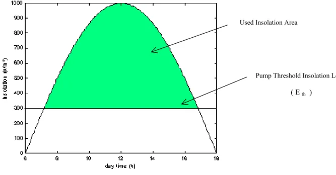
2.8 Insolation model 34
2.9 Conclusion 35
Chapter 3 : DESCRIPTION OF THE MOTOR OPERATING APPROACHES 36
3.1 Introduction 36
3.2 Constant air-gap flux operation 36
3.3 Constant motor efficiency operation 38
3.3.1 Control law Elaboration 39
3.3.2 Control law Determination 39
3.3.3 Maximum power point tracking algorithm 40
3.4 The proposed approach 41
3.4.1 Problematic 41
3.4.2 Induction motor efficiency optimisation 42
3.4.2.1 Optimisation criterion 42
A- Use of the Sinusoidal PWM strategy 42
C- Use of the the Pondered Harmonic Minimisation method 43
3.4.3 Motor power factor optimisation 43
3.5 Optimisation method 44
3.5.1 Sequential quadratic programming (SQP) 44
3.5.2 QP subproblem 45
3.5.3 SQP implementation 45
3.6 Conclusion 46
Chapter 4 : SIMULATION PERFORMANCE RESULTS 47
4.1 Introduction 47
4.2 Simulation Results 47
4.2.1 Induction motor efficiency optimisation 47
A : Sinusoidal PWM strategy 47
B : Selective harmonic elimination and Pondered Minimisation PWM 53
4.2.2 Induction motor power factor optimisation 58
4.3 Influence of head changing 60
4.3.1 The sinusoidal PWM technic 60
4.3.2 The harmonic minimisation technic 62
4.4 Influence of temperature variation 62
4.5 The economic aspect 65
4.6 Influence of the motor saturation 67
4.7 Conclusion 71
CONCLUSION 72
RECOMMENDATION 73
NOMENCLATURE
V output generator voltage (V).
I generator current (A).
Isc generator short-circuit current (A).
Vth thermic voltage (V).
Io reverse saturation current (A)
Rs series generator resistance (Ω).
Iop optimum generator current (A).
Vop optimum generator voltage (V).
Voc open circuit voltage (V).
PM maximum (optimum) generator power (W).
E insolation (W/m²).
tsr sunrise time (h). tss sunset time (h).
Vm rms motor voltage (V).
r1 stator resistance per phase (Ω).
r2 equivalent rotor resistance per phase (Ω).
rm core loss resistance (Ω).
x1 stator leakage reactance (Ω).
x2 equivalent rotor leakage reactance (Ω).
xm magnetizing reactance (Ω).
x11 stator cyclic reactance (Ω).
x22 rotor cyclic reactance (Ω).
ωs angular frequency of the supply (rd/s).
ωsl slip speed (rd/s)
ω motor speed (rd/s).
f motor frequency (Hz).
p pair pole number.
H total head (m).
Hth theoretical total head (m)
Hth ∝ theoretical total head for an infinit number of blades (m).
Q flow rate (m3/h).
ρ water volumic mass (kg/m3 ).
d1 entry impellerdiameter (cm). d2 ejection impeller diameter (cm). β2 output fluid angle (degs).
Preface 1
PREFACE
According to the World Health Organization (WHO), arround one half of the population in developing countries do not have access to safe drinking water. Unsafe water accounts for 80% of all sickness in those countries. Efforts to overcome this problem have made water pumping programs a priority of many developing countries and donor groups. In many regions this goal can be achieved by the utilisation of ground water resources. In remote areas far away from national electric grids, there are diverse possibilities to make use of this resource: hand pumps, diesel pumps or solar pumps. In comparison to diesel pumps, solar pumps are today economically
advantageous below an hydraulic equivalent (head x flow-rate) of 2000 m4. The costs are
naturally dependent on local prices. The typical heads lie between 1 m – 100 m.
The utilization of photovoltaic conversion of solar energy to power water pumps is today an emerging technology, characterized by gradually declining costs and increasing acquitance with the technology. Since the first installations in the end of the seventies, solar water pumping systems for providing domestic, livestock and irrigation water supplies in remote areas have gained enormously in acceptance, reliability and performance and nowadays belong most significant applications of photovoltaic energy. This can be mainly attributed to the fact that it is not economically viable to connect such remote locations to national electric grids. It is now estimated that over 12000 PV pump units made up of different configurations have been supplied worldwide.
The main barrier to widespread use of PVP-systems continues to be their high initial cost. The cost of water from these systems is directly related to the cost , efficiency, and reliability of the individual system components and the level of solar irradiation. The cost of photovoltaic modules accounts for between 30 % and 60 % of the total investment cost depending on the design of the system.
While improvements in the cost effective photovoltaic module manufacturing techniques are continuously researched, there still remains a clear need for development towards both improved reliability and efficiency values of solar pumping subsystems in order to extract the maximum power capability of the solar generator at all times. Thus, matching of system components, has been of interest to many workers over the last ten years .
Solar energy represents a significant potential in Algeria. Indeed, the country receives more than 3000 h of sunshine per year with a high level of radiation. The yearly average of daily solar irradiance from 5 to 7 kWh/m²/day as far as tilted surfaces at optimum angles are considered. Photovoltaic applications in situ were initiated in 1985. Also, technical and economical for research, in close collaboration with the universities, for the last twenty years.
The dissemination of PV systems is due to national programs which have been undertaken and funded by the government. The first program which was initiated in 1985 is called ‘the solar energy great south program’. This program covered a five-year period (1985-1989). Its purpose was to install stand alone PV plants for different applications. This program was achieved by the Renewable Energy Development Center (CDER). The fulfillment of this program has allowed the following:
• The electrification of small isolated villages in the sahara desert. The total power expected to be installed was 94 kWp but, only 67 kWp were effectively installed.
• Photovoltaic systems for water pumping, with a total power of 85 kWp, were installed. • A power of 30 kWp was used fot lighting in rural houses.
Preface 2
• Telecommunication repeaters were also supplied by PV modules in remote sites. The total power involved is 80 kWp.
The second program which started in 1995 is the ‘ south rural electrification program’. It is part of the national electrification program which covered the period of 1995-1998 and mobilized 24 billion Algerian dinars. The aim of this program was to supply 216,000 rural houses gathered in 4000 centers. Also this program aimed to supply more than 300 agricultural sites located near the considered centers. Furthermore, it was expected to introduce significantly, solar energy in the national energetic consumption model. The achievement of this program was assigned to the National Company of Electricity and Gaz (SONELGAZ). This program has initiated pilot projects in the sites of Tahifet (latitude 22° 53’ north, longitude 6° east and altitude 1400 m) and Imehrou (latitude 26° north, longitude 8° 50’ east and altitude 600 m). In these sites, two PV installations of 720 Wp were built and put into operation in 1992 with the aim of testing and disseminating PV programs.
In 1999, the renewable energy national program for research was adopted. The PV energy forms a significant part of this program. The main topics are summarised as follows:
• Cristalline silicon solar cells and technologies. • PV systems and components.
• PV applications.
In the scope of this program, many scientific projects have to be submitted for agreement to the National Commission for Scientific Research (CNRS). The accepted projects will be funded by the National Agency for the Development of University Research (ANDRU).
Few projects dealing with the topics mentioned above were undertaken in collaboration with foreign partners. One of the few projects carried out under an international co-operation program is the intersudmed project. Its main objective is to perform technical and economical studies dealing with the electricity production from renewable energy sources in the southern Mediterranean countries. This work is partially financed through the JOULE and INCO programs of the European Commission Directorate. Sonelgaz is the partner representing Algeria. In the case of this country, the location of Djanet (latitude 24° 33’ north, longitude 9° 28’ east and altitude 1054 m) was selected for pre-feasibility study related to the installation of medium size PV plants (~ 600 kWp) to support local diesel powered grid with production costs.
A number of types and sizes of PVP-systems are available commercially, in various stages of product development, that meet the range of existing pumping needs. The significant design variations of these systems are centered mainly on:
- The choice of the solar cell material. - The type of the electric motor. - The type of the pump.
- The method of source/load matching.
Most commercially available systems use silicon solar cells, of either mono or polycrystalline type. Other types of solar cells, which may be less expensive, are under development. There have been significant advances in the development of techniques which use thin films of
Preface 3
semiconductor materials such amorphous silicon. Other high efficient techniques using thin film cells are being extensively researched, as for example Copper-Indium-Dieselenide (CIS). PVP technology will certainly benefit from these developments in the future.
The first generation of solar pumping systems, particularly those for low and medium head applications, incorporated basically permanent magnet DC-motors. However, in the course of the last 15 years the asynchronous motor driven by a variable frequency converter has become the standard motor for solar pumping applications mainly due its simplicity, robustness and small price compared to a DC-motor.
Single-stage centrifugal pumps are frequently used for heads of less than 10 meters. For higher heads, either multi-stage centrifugal or positive displacement ( piston or progressive cavity) types are more efficient. If the pump is above ground or floating, it is usually closed coupled to the motor; if submerged, the pump may either be coupled to a submersible motor or driven by a vertical shaft. Positive displacement pumps are ordinarily submerged except in cases where the lift is small but the total head is high.
SCOPE OF THE WORK
The field experiences discussed above have shown that the PVP-technology has reached considerable maturity, the systems have been well accepted by the users, the level of reliability has improved, and that they are economically viable today, under certain conditions. However, quantitative results concerning system performance are few and far from satisfactory. These facts point out that although PVP-systems have proven themselves as one of the most favorable solutions for the supply of drinking water in dry or remotes areas of sunny regions.
The research done in the present work deals with the optimisation of the daily pumped water quantity of a PVP-system based on an induction motor since in several small scale systems, currently installed by the ‘Renewable Energy Development Center’ (CDER) in the south-East of Algeria, which are addressed especially to irrigation, we have interest to store the maximum pumped water quantity in the day before starting irrigation with pressure. The effectiveness of the proposed algorithm is described by simulation and the obtained results are compared with those of similar work pieces presented in literature.
In the present work, the operational behaviour of the different PVP-system concepts are investigated in great detail on the basis of computer simulation. For each system, mathematical models are developed and used in simulation calculations.
Chapter 1 describes a general overview of the photovoltaic technology applications, such as grid-connected and PVP- systems, their predicted advantages and drawbacks. The chapter also contains as an illustration of how a PVP works and the problems involved with it.
In chapter 2, the physical background of the individual components that form a PVP-system will be described, and the detailed mathematical models developed for each of the components will be presented.
Chapter 3 deals with an explicit presentation of the optimisation algorithm suggested in this work. It contains especially the problematic, the elaboration of the inverter control law and the main steps allowing the simulation of the proposed optimisation algorithm over a standard clear day. To carry on a comparative study, the chapter starts with a detailed description of a
Preface 4
first system called ‘the constant air-gap flux operation’. Following, similarly a second system called ‘the constant motor operation’ is presented.
In chapter 4, the simulation results are fairly presented in a comparative manner, and where the motor is controlled by one of the control laws described in the previous chapter. These results include the main performances provided by a photovoltaic pumping system such as the pump flow-rate, the daily water amount and the subsystem efficiencies. As a complementary part to this study, the economic aspect of its perspectives is unfolded at the end. It comprises the irrigated area calculated under sahara climate conditions for two crops, namely potato and tomato.
Photovoltaic Technology and Applications 5
Chapter 1
PHOTOVOLTAIC TECHNOLOGY AND
APPLICATIONS
1.1 INTRODUCTION:
As conventional energy sources are dwindling fast with a consequent rise in cost, considerable attention is being paid to other alternative sources. Solar energy which is free and abundant in most parts of the world has proven to be an economical source of energy in many applications. The energy the earth receives from the sun is so enormous and so lasting that the total energy consumed annually by the entire world is supplied in as short a time as a half hour. On a clear day the sun's radiation on the earth can be 3000 watts per square meter depending on the location. The sun is a clean and renewable energy source, which produces neither green-houseeffect gas nor noxious waste through its utilization.
The photovoltaic process is completely solid state and self contained. There are no moving parts and no materials are consumed or emitted. Consider the advantages that photovoltaic systems have over competing power options:[1]
They are non-polluting with no detectable emissions or odors.
They can be stand-alone systems that reliably operate unattended for long periods. They require no connection to an existing power source or fuel supply.
They may be combined with other power sources to increase system reliability. They can withstand severe weather conditions including snow and ice.
They consume no fossil fuels - their fuel is abundant and free.
They can be installed and upgraded as modular building blocks - as power demand increases, more photovoltaic modules may be added.
Photovoltaic (PV) is a technology in which radiant energy from the sun is converted to direct current (DC) electricity. Although the scientific basis of the photovoltaic effect has been known for nearly 150 years, the modern photovoltaic cell was not developed until 1954. Many pumping systems are at remote sites where the power demand is relatively small (< 1000 watts). Photovoltaic systems are often the most economical option for this type of application.
Unfortunately solar cells are still far to produce a significant fraction of the world’s energy needs because of the initial investment cost. However, per watt of peak power price is considerably decreasing since the seventis as shown in figure 1.2 [1]. This leads to a wide application of photovoltaic systems in several promising areas. Nevertheless, the field of application is still open to mankind creativity.
Lowering the cost of photovoltaic electricity from solar cells is essential for the technology to further extend its use, especially among utilities. Several promising areas of photovoltaic technology applications are recently in work.
Photovoltaic Technology and Applications 6
Algeria is a large area country (2382000 km²) with variety in sites leading to a diversity in climate. Solar energy represents a significant potential in Algeria. Indeed, the country receives more than 3000 h of sunshine per year with a high level of radiation.
The yearly average of daily solar irradiance from 5 to 7 kWh/m²/day (figure 1.1) as far as tilted surfaces at optimum angles are considered. Algeria can be devided into 8 climatic zones which have approximately a homogenous insolation.
Photovoltaic Technology and Applications 7
1.2 GRID CONNECTED PV SYSTEMS :
In recent years, increased advancements in equipment, technologies and reductions in price have resulted in numerous applications and increasing markets for grid-connected PV systems on residential and commercial buildings (figure 1.3).
Generally, two types of Grid-connected Photovoltaic Systems are considered [2]: - Grid-Connected PV systems without Battery storage.
- Grid-Connected PV systems with Battery storage.
FIG 1.3 Overview of the Grid-Connected PV systems [2].
1.2.1 Grid-Connected PV systems without Battery storage :
PV systems without batteries are simple and reliable, requiring little maintenance. Photovoltaic modules themselves very rarely fail or malfunction, although inverters do require occasional repair or replacement.
FIG 1.1 Trend of Solar Cell Manufacturing Cost
Photovoltaic Technology and Applications 8
Grid-connected or utility-interactive PV systems are designed to operate in parallel
and interconnected with the electric utility grid as shown in figure 1.4. The primary component in grid-connected PV systems is the inverter, or power-conditioning unit (PCU). The PCU converts the DC power produced by the PV array into AC power consistent with the voltage and power quality requirements of the utility grid. A bi-directional interface is made between the PV system AC output circuits and the electric utility network, typically at an on-site distribution panel or service entrance. This allows the AC power produced by the PV system to either supply on-site electrical loads, or to back feed the grid when the PV system output is greater than the on-site load demand. At night and during other periods when the electrical loads are greater than the PV system output, the balance of power required by the loads is received from the electric utility. When the utility grid is down, these systems automatically shut down and disconnect from the grid. This safety feature is required in all grid-connected PV systems, and ensures that the PV system will not continue to operate and feed back onto the utility grid when the grid is down for service or repair [2].
FIG 1.4 Synoptic of Grid-Connected systems without batteries [2].
A typical interconnection of a grid-connected PV power plant including two dc-ac inverters and transformers is shown in figure 1.5. The capacitor in parallel with the PV array operates to limit the change of the PV voltage, Vpv, supplied to the dc-ac inverters. The inverters comprise of two 6-switch 3-phase bridge converters. Switching signals for the inverters are generated by a neural network controller for MPPT of the PV array. The objective of the transformer setup is to reduce harmonics involved in the inverter output ac voltage [3].
FIG 1.5 Diagram of the grid-connected PV system [3].
1.2.2 Grid-Connected PV systems with Battery storage:
This type of system is extremely popular for homeowners and small businesses where backup power is required for critical loads such as refrigeration, lighting and other necessities
Photovoltaic Technology and Applications 9
(figure 1.6). Under normal circumstances, the system operates in a grid-connected mode, supplementing the on-site loads or sending excess power back onto the grid while keeping the battery fully charged. In the event the grid becomes de-energized, control circuitry in the inverter opens the connection with the utility through a bus transfer mechanism, and operates the inverter from the battery to supply power to the dedicated critical loads only. In this
configuration, the critical loads must be supplied from a dedicated sub panel [2].
FIG 1.6 Synoptic of Grid-Connected systems with battery storage included [2]. From an operational point of view, a photovoltaic array experiences large variations of its output power under intermittent weather conditions. Those phenomena may cause
operational problems at a central control center in a power utility, such as excessive frequency deviations, spinning reserve increase, etc. Figure 1.7 illustrates two samples of PV power variations for one day [3].
FIG 1.7 Samples of PV power output variations [3].
One method to overcome the above problem is to integrate the PV power plant with other power sources such as diesel backup, fuel cell backup or battery backup. The diesel backup for PV power is able to make a continuous 24-hour power supply be possible. However, it has a couple of severe drawbacks. Its electricity efficiency decreases significantly at a low level of power output, and the diesel power generation is environmentally detrimental as well. Both the battery backup and the fuel cell backup are the most likely technologies to provide backup power for the PV power system in the near future.
A fuel cell power is a very attractive option being used with an intermittent power generation source like the PV power because the fuel cell power system contains lots of great features such as high efficiency, fast load-response, modular production and fuel flexibility. Its feasibility in coordination with a photovoltaic power system has been successfully
Photovoltaic Technology and Applications 10
demonstrated for both grid-connected and stand-alone applications [3]. Due to the fast ramping capability of the fuel cell power system, a PV-fuel cell hybrid system may be able to solve the PV’s inherent problem of intermittent power generation. Unlike a storage battery, which also contains attractive attributes such as fast response rate, modular construction and flexibility for site selection, the fuel cell power can produce electricity continuously to support the PV power. Therefore, the quality of overall power generated from the PV-fuel cell hybrid power plant may be improved. The combination of the photovoltaic and fuel cell power plants is now a viable technology to commercial applications.
Figure 1.8 illustrates a simplified diagram of a grid-connected PV-fuel cell hybrid power plant [3].
FIG 1.8 Diagram of the grid-connected PV-fuel system [3].
1.3 THE PV–POWERED SOLAR DOMESTIC HOT WATER SYSTEMS:
An alternative means of deriving water heating from the sun was patented by Fanney and Dougherty in 1994. The basic photovoltaic-powered solar domestic hot water (PV-SDHW) system consists of a photovoltaic (PV) array connected to several resistive heating elements within a water storage tank. The PV array produces electrical power during periods of solar insolation and this power is immediately dissipated in the resistive elements.
Several configurations of the PV-SDHW system have been proposed. The original design consists of two water storage tanks as depicted in figure 1.9.
A preheat tank heats water drawn from the water mains by thermal energy derived from six resistive elements connected to the PV array. Three of the resistive elements are located in the upper heating element port and three in the lower port.
The auxiliary tank draws water from the preheat tank and performs any additional heating required via two AC resistive elements connected to the utility grid. Other configurations of one –tank are currently suggested which allows the reduction of the overall system cost [4].
Photovoltaic Technology and Applications 11
FIG 1.9 Two-tank PV-SDHW system configuration [4].
The PV-SDHW concept has several potential advantages over its solar thermal rivals :
The PV-SDHW system eliminates the plumbing required in a thermal SDHW system. These pipes can be a significant source of heat losses.
The new system requires no heat exchanger. These heat exchangers reduce the efficiency of thermal SDHW systems.
The installation of a PV-SDHW system is simpler than for a thermal system. The PV-SDHW system also possess a couple of key disadvantages relative to the traditional thermal system :
For systems sized to meet the same load, the PV array of a PV-SDHW system may cost two to three times the total cost of purchasing and installing a thermal SDHW system.
The necessary surface area of the PV array for a PV-SDHW system may be three to five times greater than that of the collectors of a thermal SDHW system of comparable performance. This larger area results primarily from the lower solar energy conversion efficiency of PV arrays in comparison to thermal collectors.
1.4 THE PHOTOVOLTAIC WATER PUMPING SYSTEMS :
According to the World Health Organisation (WHO), around one half of the population in developing countries do not have access to safe drinking water. Efforts to overcome this problem have made water pumping programs a priority of many developing countries. In remote areas far away from national electric grids, the use of solar pumps is today economically advantageous where the typical heads lie between 1m-100m [5].
The utilisation of photovoltaic conversion to power water pumps is today an emerging technology, characterised by gradually declining costs. It is now estimated that over 12000 pump units made up of different configurations have been supplied worldwide.
The main barrier to a widespread use of PVP- systems continues to be their high initial cost. The cost of the photovoltaic parts accounts for 60% of the total investment cost.
Photovoltaic Technology and Applications 12
Figure 1.10 gives the contribution of various components to the overall cost of PVP-systems [5].
FIG 1.10 Contribution of various components to investment cost of PVP systems [10].
A number of types and sizes of PVP-systems are available commercially, in various stages of product development, that meet the range of existing pumping needs. The significant design variations of these systems are centered mainly on :
• The choise of the solar cell material. • The type of electric motor.
• The type of pump and the method of source/load matching.
Single-stage centrifugal pumps are frequently used for heads of less than 10 meters. For higher heads, either multi-stage centrifugal or positive displacement (piston or progressive cavity) types are more efficient. If the pump is above ground, it is straight coupled to the motor. If submerged, the pump may either be coupled to a submersible motor or driven by a vertical shaft.
PV-pumping efficiency has considerably improved. System efficiencies from 1-3 % in 1981 have been raised up to 3.5-5% in 1990. Novel system technics are available with efficiencies of more than 5% [5].
The usual elements of a PV water pumping system are:
• Photovoltaic array – to provide electricity supply for the motor-pump. This
supply could be direct current (DC), usually at 110 volts, or alternating current (AC) which is produced by inverting the DC power to AC power.
• Motor-Pump set.
• Battery storage if used – to provide electricity storage and allow pumping in cloudy conditions or at night.
• Storage tank – normally elevated, making water available at night or when it is cloudy.
• Maximum power point tracker (MPPT) which forces the PV array to generate its maximum power. PV-Modules 60 % Piping 17% Installation 9 % Inverter 10 % Motor / Pump set
Photovoltaic Technology and Applications 13
The volume of pumped water is dependent on five major factors:
• The radiation level which is a measure of the sun’s available energy. • The photovoltaic array area.
• The conversion efficiency of the photovoltaic array. • The ambient temperature.
• The pump-motor –hydraulic system characteristics. Three different system configurations are currently in use :
• The first is the directly coupled system where a PV array is directly coupled to a DC motor and a pump.
• The second system is the battery buffered PV pumping system where a battery is connected across the array to feed the DC motor driving a pump.
• The third system uses maximum power point tracker (MPPT) or array tracking to improve the efficiency of system.
The typical range of sizes for photovoltaic-powered pumps is a few hundred watts to a few kilowatts.
Direct coupled systems, where the PV array is directly coupled to a DC motor-pump system, is shown in figure 1.11. Such a system is simple and reliable, but the system does not operate continuously at its optimum point due to the continuous variation of solar radiation .
FIG 1.11 Direct coupled PV pumping system
Battery buffered systems with a storage battery is shown in figure 1.12. In this system, a battery is connected across the PV array and the DC motor is operating at almost constant voltage, and as a result, the DC motor is operated close to its optimum operating point. This system has two advantages over the directly coupled one:
• water may be pumped day and night, thus the water discharge is larger.
• the DC motor is operating at its optimum operating point, and consequently, the system efficiency is enhanced.
A major disadvantage of such a system is the extra system cost and unreliability due to the battery.
Photovoltaic Technology and Applications 14
The photovoltaic modules are often mounted on a tracking device that maximize energy production by tracking the sun from east to west each day as shown in figure 1.13. The tracker uses little or no power and may increase water production as much as 20 to 40 percent during summer months [1].
FIG 1.13 PV pumping scheme with sun tracking
1.5 BACKGROUND OF PHOPTOVOLTAIC PUMPING SYSTEMS :
The PV power sources are, by nature, non-linear. They are subject to large variation under environmental factors, mainly the insolation and cell temperature. In order to speed up the amortisation of the system cost, it is essential to opearate the PV generator at its maximum power point on a continuous basis. Therefore power-conditioning units are used for this purpose. This unit depends on the type of load being feed by the PV array. For a pumping system, the load is generally a DC or AC motor.
The first generation of solar pumping systems, particularly those for low and medium head applications, incorporated basically permanent magnet DC motors. However in the course of the last 10 years the asynchronous motor driven by a variable frequency converter has become the standard for solar pumping applications because of its simplicity, robustness and low price compared to DC motor. Electronically-commuted brushless DC motors have in the last 5 years or so gained much popularity because they require less maintenance than standard DC motors.
Many researchers have investigated and proposed different methods for designing and optimising the PVPS to improve system efficiency and reduce investments. Such systems operate in open-loop speed control because precision and transient performance are not required. In addition, the system operates at steady state for long periods.
Several experimental results and theoritical analyses of PVPS have been published. The simplest way to achieve a pumping system is to perform a direct coupling of the motor-pump to the PV generator. In [6] Hsiao describes such impementation. However, even the size is initially optimised, it is shown that the efficiency varies broadly on insolation. It is seen that, depending on the load I-V characteristic, a directly connected motor-PV system with a given load characteristic can be naturally optimised at the intersection point of the load characteristic and maximum power locus. This occurs for one value of insolation. As the insolation varies, the system becomes sub-optimal. In order to track the maximum power various techniques are used; these are called Maximum Power Point Trackers or MPPT technics. These technics are devided in two sets [7]: fixed voltage and true MPPT. For the first technic, there are two ways to implement it. The reference voltage can be a constant predetermined value derived from observing the generator characteristic and choosing a single
value thereafter. This value is chosen around 62-80 % of the open circuit Voc [8]. In the
Photovoltaic Technology and Applications 15
short- circuit current Isc. A pilot module is then used to track the new reference current when
the insolation varies [9].
As the power drawn from a PV generator depends on insolation, temperature and array
voltage, it is necessary to match the load and PV array. Several ways have been tried out in order to seek the maximum power point [10-11]. The ideal way is to calculate the output power and compare it with the ideal one . The system is then pushed towards the operating point. This method is tedious, complex and time consuming. The accuracy is affected for low insolation levels because the integration becomes more difficult. One possibility is to exploit perturbation technics, in which the operating point is moved towards the maximum power by perturbing the system periodically by increasing or decreasing the array voltage [11-12-13]. If a given perturbation leads to an increase (decrease) in array power, the subsequent perturbation is made in the same (opposite) direction. Hence the MPPT hunts continuously the peak power operating condition. Since the PV power sources are generally connected to various load types such as energy storage [14], fuel cells [3], therefore designing systematically an MPPT controller is not an easy task. Thus modern control approaches, such as Fuzzy Logic, Neural Network have been suggested for fullfiling the function of tracking the maximum power point of a PV system [10-12-15-16-17--18]. In [10], the search is based on fuzzy heuristic rules which claims not to need parameter information. Thus no transducers were used in this application. Tsai-Fu Wu [12] has proposed a fuzzy logic controlled lightning system with battery backup powered by a solar cell generator. A fuzzy logic controller was suggested to control the battery charge/discharge and maximum power point tracking using a a perturb and observe algorithm. These are collected by the fuzzy rule algorithm and used to control the system to meet the desired performances after the defuzzification process. Artificial neural networks ANN have been reported by other authors. An ANN based real-time maximum power tracking controller for a PV grid-connected system was reported in
[15-17]. In order to estimate the optimal power, the open circuit Voc and the short circuit current
Isc are measured through monitoring cells and mapped to the optimal inverter voltage which
is fed to switching control of the inverter. However, a non-linear identification is necessary to
get the optimal voltage from the measured Voc. An ANN is therefore used for this estimation
purpose. In another publication, the same authors used only the actual array voltage Vg and
Voc for maximum power tracking [16].
One can optimise either the gross mechanical output power [19-20] or the motor efficiency [21-22-23-24]. It is shown that motor efficiency optimisation diminishes the PV generator efficiency.
In [25] Appelbaum analysed starting and steady-state characteistics of a DC motor powered by PV cell generator. It was found that the starting time is larger when any type od DC machines is connected PV source. In addition, the system starts to rotate only at high insolation level for constant load characteristics. For aerodynamic load (centrifugal pumps), the system requires a relatively lower static torque and the system starts to rotate at lower insolation level. Appelbaum and Sarm [26] have examined the starting of a DC motor - pump powered by a PV array with/out MPPT. Alghuwainem [27] exposed the steady state operation of a separatly excited DC motor with Step Up converter working as an MPPT. Anis et al [28] reported that a load composed of a DC motor driving a constant volume pump represents a non-matched load for PV array. The matching of a DC motor to a PV generator to maximise gross mechanical energy has been reported by Saied [19] and Akbaba et al [20]. Weiner et al [29] have examined the global efficiency optimisation of a PVPS based on a DC motor. In [11], Atlas et al experimentally proposed an algorithm witch determines the MPP for a PV array for any temperature and solar irradiance level and where the pump is coupled to a PMDC motor. In [30], Veerachary et al proposed a Neural Network algorithm of an MPP tracking for PV supplied DC motors.
Photovoltaic Technology and Applications 16
In [8] , Langridge et al studied the operation of a direct PVPS based on a brushless DC motor driving a helical rotor pump and where the array maximum power is made available by a proper control. The reference array voltage is based on a fraction of the open circuit voltage. Moussi et al [22] proposed an optimal operation of a PVPS using a BLDC motor driving a centrifugal pump. The purpose was the maximisation of the daily pumped water amount by a proper adjustment of the motor voltage. The dynamic performance of a permanent magnet BLDC motor powered by a PV array were investigated by Swamy et al [31].
Since the use of brushless permanent magnet motors is limited to low power PV systems due to their high cost, several PVPS based on an induction motor fed either by a voltage source inverter or a current source inverter have been proposed with scalar and vector control strategies. These works treated various optimisation approaches, such as improving the array use efficiency, or maximising the pump flow-rate. Bhat et al [32] analysed a vector control of an induction motor fed by a PV source via a current-controlled voltage source inverter (CC-VSI) . The motor was controlled so to improve the system efficiency. The array maximum power is continuously extracted via a boost-chopper. Yao et al [33] proposed to achieve a permanent optimal motor efficiency value for any insolation level with an appropiate frequency control of a VS inverter. In [21], Aziza et al investigated the case of a PV pumping system based on an induction motor for a maximum gross mechanical power operation through the control of a voltage source inverter feeding the motor. Olorunfemi [34] proposed the transient and steady state analysis of an induction motor fed from a PV source through a current-source inverter and where the extracted electric power is properly controlled by the chopping ratio of a buck-boost converter. For steady state, chopping ratio and slip frequency of the inverter were manipulated to achieve a maximum efficiency. The analysis of small signal perturbation showed that the system is lightly damped for operating voltages of the array that are less than that of the array voltage corresponding to array maximum output power and the system presents a non-minimum phase response. In [35], Nayar et al described two schemes of a solar water pumping system using an induction motor driving a submersible pump. In the first scheme, the pannel output voltage was converted into AC by a three phase PWM inverter. The output voltage is stepped up by a three phase transformer before connecting to the motor. In the second scheme, the panel voltage was boosted by a microprocessor controlled dc-dc converter.The dc output voltage from the booster was then converted into AC by the PWM inverter. The major control systems involved in the system is to achieve a constant V/f operation. The inverter acts as both a variable-frequency source to improve the output of the water pump and a peak-power tracker. Betka et Moussi [23] proposed the daily water amount maximisation of a PVPS using an induction motor fed by an optimal PWM inverter. This was achieved by a proper control of four swiching angles. In addition the electric power was controlled via the inverter frequency instead of the MPPT circuit. Other works treated the operation of the two – phase induction motor [36] or the single-phase in photovoltaic pumping applications.
1.6 CONCLUSION :
Essential information about PV arrays and their connection to several technology applications systems has been presented in this chapter. Renewable energy technologies must do more than be environmentally friendly to be successful; they must also be economically feasible. A failure to meet this second requirement is the reason that many renewable energy applications have not gained more widespread acceptance. The major drawback which limits these applications is the initial cost of the plant. Neverthless, several promising areas of photovoltaic technology applications such as water pumping in remote areas are recently in
Photovoltaic Technology and Applications 17
work. An explicit study of a PVP system based on an induction motor driving a centrifugal pump will be the focus of next chapters.
Modelling of the Photovoltaic Pumping System 18
Chapter 2
MODELLING OF THE PHOTOVOLTAIC
PUMPING SYSTEM
2.1 INTRODUCTION :
The philosophy behind digital simulation of renewable energy systems is that experiments which normally should be done on real systems under high assembling costs can be done numerically in a short time on a computer, thus saving time and investments.
Digital simulation of these systems serve for the purpose of understanding the operational behaviour of the various components of the system and the interaction among them, since by simulating the system performance, one can trace all steps of energy conversion and identify the losses throughout the system in details. Because computer simulation allows a wide range of system parameters to be varied, and the operating characteristics of the system to be investigated. Finally, computer simulation permits the extrapolation of a system design to other localities, with different meteorological conditions, and make it possible to compare different systems. Basis for a computer simulation is a reflection of a real system which is based on theoretical analysis of the various physical processes occurring in a system. Mathematical equations describing quantitatively the system characteristics are formulated from this analysis and translated into computer to be used in the simulation process.
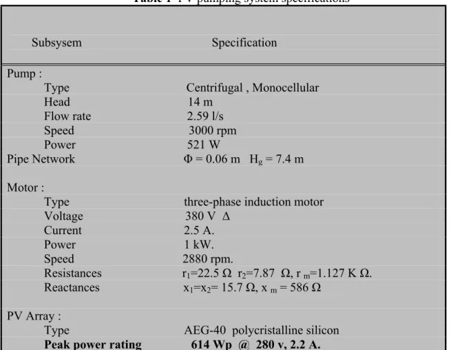
The schematic diagram of the photovoltaic pumping system analysed in this thesis is shown in Figure 2.1. It consists of a photovoltaic array, a PWM voltage source inverter and a three-phase squirrel cage induction motor driving a monocellular centrifugal pump. The specification of different components is illustrated in Table 1.
In the derivation of the system equations, some assumptions are made: ♦ The motor is supposed to be unsaturated.
♦ The power losses in the inverter and stray losses in the motor are also supposed negligible. Furthermore, dynamic equations are not taken into consideration since the system is assumed to run at steady state.
In this work, prior to global system simulation, each component of the proposed system should be studied and mathematical model deduced thereafter.
FIG 2.1 The proposed PV Scheme Structure
PV Array Control Unit Centrifugal Pump V S Inverter Ind. Mot V C
Modelling of the Photovoltaic Pumping System 19
Table 1 PV pumping system specifications Subsysem Specification
Pump :
Type Centrifugal , Monocellular Head 14 m Flow rate 2.59 l/s Speed 3000 rpm Power 521 W Pipe Network Φ = 0.06 m Hg = 7.4 m Motor :
Type three-phase induction motor Voltage 380 V ∆ Current 2.5 A. Power 1 kW. Speed 2880 rpm. Resistances r1=22.5 Ω r2=7.87 Ω, r m=1.127 K Ω. Reactances x1=x2= 15.7 Ω, x m = 586 Ω PV Array :
Type AEG-40 polycristalline silicon Peak power rating 614 Wp @ 280 v, 2.2 A.
2.2 THE PHOTOVOLTAIC EFFECT :
A brief description of the physics behind photovoltaics is helpful in understanding the origin of the equivalent circuits used to model these devices. Photovoltaic cells are semiconductor devices; the vast majority of commercial PV cells are fabricated from silicon. A PV cell may consist of a single crystal, a number of smaller crystals (polycrystalline), or it may lack crystal structure all together (amorphous). Other semi-conducting materials such as gallium, arsenide are employed in PVs for extraterrestrial or sun concentrator applications, but this description will concern a silicon PV cell.
A PV cell is essentially a large diode that produces a voltage when exposed to incident light. It may be considered to be a light-emitting diode “run backward;” the analogy is similar to a heat engine and a refrigerator. The semiconductor band-gap is the difference in energy between valence and conduction bands. It is a material-dependent property; in undoped
silicon it has a value of 1.12 electron-volts or 1.79x10⁻¹⁹joules. An incident photon with at
least this much energy may interact with a valence electron in the p-type material, forcing it up into the conduction band, Figure 2.2. Any photon with a wavelength less than about 1100 nm has sufficient energy to initiate this reaction. This wavelength corresponds to radiation in the near infrared portion of the spectrum.
If the PV cell is connected to a load in a closed loop circuit, the new conduction band
electron will be repelled by the excess negative charge in the p-type side of the PV cell. It travels through the circuit, producing a current through the load [37].
Modelling of the Photovoltaic Pumping System 20
FIG 2.2 Photovoltaic effect- Incident Light Moves an electron from the valence band to the conduction band
FIG 2.2 Photovoltaic effect-incident light moves an electron from the valence band to the conduction band [37].
2.3 THE PHOTOVOLTAIC GENERATOR MODEL :
Photovoltaic generators are neither constant voltage sources nor current sources but can be approximated as current generators with dependant voltage sources. The array considered in this study is a 16 series connected modules type AEG.40, each having a rated peak power of 38 w and containing 36 series/parallel cells. For the modelling of the PV generator, either the called ‘One exponential Model’ or the ‘Two exponential Model’ have been widely used in literature to describe the electrical characteristics of a solar cell.
2.3.1 The One Exponential Model :
The PV generator is a non-linear device and is usually described by its I-V characteristics and by the equivalent circuit, as shown in figure 2.3; this model called also
‘the Four-Parameter Model’ which is widly used by different softwares such as TRNSYS
[37], developped by Eckstein (1990), assumes that the PV generator may be modeled as an
insolation–dependent current source in parallel with a diode. The current source IL represents
the light-generated current and is function of the cell-characteristics, cell temperature and insolation level. The diode which represents the p-n junction of the silicon cell provides a means for some current to be shunted across the load without actually reaching it. Physically, this is equivalent to a photoelectron falling back into a valence hole before leaving the semi-conductor material; if this occurs the electron can no longer contribute to useful current. In addition to the photo-current source and diode, a single resistor is added to the model to account for ohmic losses as current travels through the PV generator. The four-parameter model has been implemented into many programs, and it reliably predicts with success the performance of single crystal and polycrystalline PV arrays. The four parameter model
assumes that the slope of the IV curve is flat at the short-circuit region ( 0
dVdI = at V= 0).
Therefore the effect of the shunt resistance is negligible, since its value is generally very high[37].
However, this assumption is not generally valid for amorphous photovoltaics. The short-circuit IV slope is finite and negative, so the four-parameter model cannot reproduce I-V characteristics typical of amorphous silicon. A modification is necessary to broaden the model to include amorphous PV cells.
p- Type Material n- Type Material
Modelling of the Photovoltaic Pumping System 21
The "five-parameter model" introduces a shunt resistance in the PV equivalent circuit.
In the ‘four parameter model’ which is adopted in the present work , the I-V characteristic at a given insolation level can be expressed in an implicit equation as follow [24]:
+ = - 1 V I . R V exp . I -I I th S 0 sc (2.1)
Where I and V represent the current and the voltage at the load. The useful power generated by the PV is the product of these two quantities.
In equation (2.1), the reverse saturation current Io and the thermal voltage Vth are written in
terms of manufacturer generator data obtained at 1000 w/m² and 25°C [22]:
(
)
+ − − = th op s op op sc o V I . R V exp . I I I (2.2)(
)
− − + = op op oc op s op th V I 1 Ln V I . R V V (2.3)The cell temperature Tc iscalculated by a simplified linear relationship as a function of the
incident global insolation E, and where the ambiant Temperature Ta determines the crossing
point of the function on the vertical axis [8] :
(
)
800 E 20 NOCT T Tc = a + − (2.4)NOCT denotes the Normal operation Cell Temperature, which indicates the junction temperature at 800 w/m² and 20°c; the wind velocity is assumed to be1m/s.
FIG 2.3 The four parameters equivalent circuit
2.3.2 The Two Exponential Model :
For the modelling of a PV generator, the so called ‘Two Exponential Model’ has been also used in several softwares such as the block oriented simulation system INSEL [5]. The relationship between the voltage V and the generator current is given by the following equation : − β + − − α + − = 1 V . I . R V exp I 1 V . I . R V exp I I I th s 2 o th s 1 o sc (2.5)
Modelling of the Photovoltaic Pumping System 22
It is obvious that the main difference with the previous model is the presence of two exponential factors in the mathematical model.
The cell ideality factors are assumed to be α = 2 and β = 2 according to [5].
In addition, The two reverse saturation currents Io1 and Io2 are expressed by the following
quantities : − = 1 T . k V . e exp I 2 1 I c oc sc 1 O (2.6) − = 1 T . k . 2 V . e exp I 2 1 I c oc sc 2 O (2.7)
k denotes the Boltzmann constant ( k = 1.381. 1023 J/K) and e is the electron charge (e =
1.602 .10-19 C).
FIG 2.4 The two-diodes model equivalent circuit
Besides, the generator ‘four model’ parameters are related to those of a single module via the following expressions and where the index ‘mod’ denotes ‘module’:
Isc = Np . Isc ‘ mod ’ Iop = Np . Iop ‘ mod ’ Voc = Ns . Voc ‘ mod ’ Vop = Ns . Vop ‘ mod ’ mod' ' s p s s R N N R =
Ns and Np are respectively the number of modules in series and the number of strings in
parallel.
The I-V curve is essentially affected by the variation of two inputs: the solar insolation and the array temperature. The adaptation of equation (2.1) for different levels of solar insolation and temperature can be handled by the following equations [24] :
T T T = − r ∆ (2.8) sc r r I ) 1 E E ( T E E I ∆ + − α = ∆ (2.9) I R T V = − β∆ − s ∆ ∆ (2.10) I I I = r + ∆ (2.11)
Modelling of the Photovoltaic Pumping System 23
The characteristics of any PV generator may be simulated through equations (2.1) to (2.11) under a variety of operating conditions ( ambiant temperature, insolation, cloud cover, etc).
Figure 2.5 shows typical I-V characteristics for increasing insolation levels of the used PV array. One could see that short circuit current varies in proportion to the insolation level, while the open circuit voltage is approximately constant. Consequently the extracted
electric power will increase accordingly. Each curve has a maximum power point PM (dashed
line), which is the optimal operating point for an efficient use of the solar array.
FIG 2. 5 I-V Characteristics for variable Insolation level ( Tc = 25°C ).
Since the operating temperature of a solar cell varies over a wide range, it is essential to understand the effect of temperature changes on both the open circuit voltage and short circuit current. The current increases slightly as the temperature increases; this is due to increased light absorption. However, as the temperature increases the open circuit voltage
tends to decrease as shown in Figure 2.6. As a result of Voc reduction, the output power
decreases by 0.44 %/°C for the used array.
0 50 100 150 200 250 300 350 0 0.5 1 1.5 2 2.5 V (V) I ( A ) E = 200 w / m² E = 1000 w / m² PM T5 0 50 100 150 200 250 300 350 0 0. 5 1 1. 5 2 2. 5 V (v) I ( A ) T5 > …. > T1 T1 T5
Modelling of the Photovoltaic Pumping System 24
To avoid the destruction of PV-cells due to the ‘hot-spot effect’, manufacturers connect by-pass diodes over a group of cells, figure 2.7; with this arrangement a substring with a shaded cell will be short-circuited by the by-pass diode and the non-shaded substrings can work, but the energy from the by-passed substring is lost. It is important to underline that this is normally only a method for the protection of PV cells. If by-pass diodes are to be used to make the PV-module more shade-tolerant, they should be connected to significantly fewer PV cells [37].
FIG 2.7 Protection by by-pass diodes[37] 2.3.3 The Conversion efficiency :
The conversion efficiency of a PV generator is defined as the ratio of the useful maximum electrical power output to the incident solar power [25] :
A . E I . V ηcon = op op (2.12)
A is the generator effective area in m².
Manufacturers may quote a “reference efficiency.” This is simply the module efficiency at
reference testing conditions, taken generally for an insolation of 1000 W/m2 and a cell
temperature of 25° C. The maximum power is given as the product of current and voltage at the maximum power point.
Figure 2.8 shows performance levels reached over the last 50 years development period, showing that the rate of progress varying quite significantly with material understanding [5].
Modelling of the Photovoltaic Pumping System 25
2.3.4 The Form Factor :
This is a module performance factor, identified by the ratio of the maximum extracted power to the product of the short-circuit current and the open-circuit voltage [23]:
oc sc op op
V
.
I
I
.
V
FF
=
(2.13)2.4 THE VOLTAGE SOURCE INVERTER MODEL :
The supply of an induction motor by the solar generator requires the use of an inverter which transforms the DC-voltage into a three phase AC-system with variable frequency and voltage. There are two basic types of forced-commutated inverter : The current source
inverter and the voltage source inverter .
In photovoltaic pumping applications, it has been concluded that the latter inverter is considered the best choice [5]. Other types of inverters such as multi–level inverter with separated DC sources and Optimised harmonic-stepped waveform technic [38] which is well adapted in such applications can also be used.
2.4.1 Converter Requirements :
Basic requirements imposed to DC-AC converter are :
• Generate smooth Variable-Frequency Variable-Voltage (VVVF) power.
• Produce nearly sinusoidal current waveforms throughout the operating range to avoid
undesirable torque oscillations
• Permit highly dynamic controlboth in motoring and braking operation.
• Provide as nearly as possible equivalent performance to the dual converter-fed dc drives as regards cost, service reliability, and harmonic effect on the system.
In the scope of the present work, three different technics are used to control the VS inverter feeding the induction motor.
2.4.2 Sinusoidal PWM Strategy :
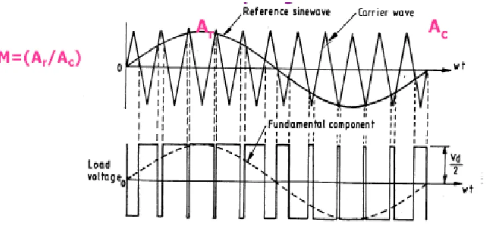
A natural PWM switching technique is used to drive the full bridge inverter with an amplitude modulation index M and a frequency modulation index P. The capacitor across the inverter input terminals as shown in figure 2.1, serves to smooth the output voltage of the DC source and to reduce the source impedance. The three phase inverter consists of three legs, one for each phase. It is assumed that the switches and diodes are ideal devices. The control signals are generated by modulating three low frequency sinusoidal signals (called reference waveforms) with a common high frequency triangular carrier wave as shown in figure 2.9. The switching instants are determined by the crossover of the two waveforms.
Modelling of the Photovoltaic Pumping System 26
As shown in figure 2.10, for a balanced, three-phase, star connected, the r.m.s value of
the fundamental component of the modulated line to neutral voltage Vm is proportional to M
in the range of 0 ≤ M ≤ 1, for all values of P> 9 [39]: 2
V . M
Vm = (2.14)
An increase of the fundamental component is possible by making M>1; however Vm
will be no longer proportional to M. In this condition of overmodulation, some intersections between the carrier wave and the modulating wave are lost [40]. In the extreme, when M reaches the value M = 3.24 the original forms of PWM waveform are lost and the phase voltages then revert to the quasi-square wave-shape.
FIG 2.10 Voltage index-rms value relationship [39]
In the present study, the carrier frequency is fixed at 750 Hz and P is set at
P = 15 for the nominal insolation level E = 1000 W/m². Consequently, the motor will be unaffected by the high order harmonics generated by the inverter for all insolation levels since these harmonics, which appear as side-bands centred around the switching frequency multiples (k.P.f) are naturally filtered by the motor itself.
2.4.3 Selective Harmonic Elimination PWM Strategy (SHE PWM) :
In this method called also Optimal PWM Control, the (m-1) unwanted lowest odd harmonics of a square wave need to be eliminated and the fundamental voltage component can be controlled.
V12 (r.m.s) / V
Linear Overmodulation Square-wave
M
1 3.24
0.612 0.78
Modelling of the Photovoltaic Pumping System 27
To achieve this, the inverter switchings occur at chops defined as α1, α2, …., αm in a quarter-cycle of the period as shown in figure 2.11. Fourrier analysis of the above waveform indicates that the rms value of the nth harmonic is given by [39] :
+ α π =
∑
= ) (n. cos . (-1) 2. 1 . V . n 2 2. V m i 1 i i m (2.15)Generally, in a three-phase system, the lowest non-triplen harmonic components are to be eliminated, whereas, all triplen-harmonics are naturally eliminated.
In the present case, the fundamental component is controlled throughout the continuous
control of the switching angles αi, which are adjusted properly to eliminate the lowest order
harmonics 5, 7 and 11. Thereafter, the four angles are obtained by resolving the following equations [23]:
( )
( )
( )
( )
α + α − α + α − π = 4 3 2 1 m cos . 2 cos . 2 cos . 2 cos . 2 1 V 2 . 2 V (2.16)(
)
(
)
(
5.)
2.cos(
5.)
0 cos 2. -. 5 cos 2. . 5 cos 2. -1 4 3 2 1 = α + α α + α (2.17)(
)
(
)
(
7.)
2.cos(
7.)
0 cos 2. -. 7 cos 2. . 7 cos 2. -1 4 3 2 1 = α + α α + α (2.18)(
)
(
)
(
11.)
2.cos(
11.)
0 cos 2. -. 11 cos 2. . 11 cos 2. -1 4 3 2 1 = α + α α + α (2.19) 4 0 ≤ α1 ≤ α2 ≤ α3 ≤ α4 ≤ π ( 2.20)FIG 2.11 Polar voltage curve of a PWM inverter
The non-linear nature of the above equations calls the use of numerical resolution methods such as Newton-Raphson to get the required solution. For an eventual implementation, the switching angles could be stored in look-up tables and then sent to down-counters .
2.4.4 The Pondered Harmonic Minimization Strategy :
Instead of eliminating specific harmonics, one could use another alternative where performance indexes are considered. This approach is to define a performance index related to the undesirable effects of the harmonics and to select the switching angles so that the fundamental voltage is controlled and the performance index is minimised. This is called a
α 1 α 2 α 3 α 4 90° 180° ½ V - ½ V Polar voltage α
![FIG 1.3 Overview of the Grid-Connected PV systems [2].](https://thumb-eu.123doks.com/thumbv2/123doknet/14913241.659488/15.892.196.667.101.425/fig-overview-grid-connected-pv-systems.webp)
![Figure 1.8 illustrates a simplified diagram of a grid-connected PV-fuel cell hybrid power plant [3]](https://thumb-eu.123doks.com/thumbv2/123doknet/14913241.659488/18.892.213.718.365.623/figure-illustrates-simplified-diagram-connected-hybrid-power-plant.webp)
![Figure 1.10 gives the contribution of various components to the overall cost of PVP-systems [5]](https://thumb-eu.123doks.com/thumbv2/123doknet/14913241.659488/20.892.185.693.171.434/figure-gives-contribution-various-components-overall-cost-systems.webp)
![FIG 2.2 Photovoltaic effect-incident light moves an electron from the valence band to the conduction band [37]](https://thumb-eu.123doks.com/thumbv2/123doknet/14913241.659488/28.892.232.771.127.330/photovoltaic-effect-incident-light-moves-electron-valence-conduction.webp)

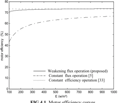
![Figure 4.3 displays the improvement brought to the pump efficiency by the proposed technique, as well as that described in [33]](https://thumb-eu.123doks.com/thumbv2/123doknet/14913241.659488/57.892.240.682.298.627/figure-displays-improvement-brought-efficiency-proposed-technique-described.webp)