HAL Id: hal-00728577
https://hal.archives-ouvertes.fr/hal-00728577
Submitted on 30 Aug 2012
HAL is a multi-disciplinary open access
archive for the deposit and dissemination of
sci-entific research documents, whether they are
pub-lished or not. The documents may come from
teaching and research institutions in France or
abroad, or from public or private research centers.
L’archive ouverte pluridisciplinaire HAL, est
destinée au dépôt et à la diffusion de documents
scientifiques de niveau recherche, publiés ou non,
émanant des établissements d’enseignement et de
recherche français ou étrangers, des laboratoires
publics ou privés.
A formal design synthesis and optimization method for
systems architectures
Nicolas Albarello, Jean-Baptiste Welcomme, Claude Reyterou
To cite this version:
Nicolas Albarello, Jean-Baptiste Welcomme, Claude Reyterou. A formal design synthesis and
opti-mization method for systems architectures. 9th International Conference on Modeling, Optiopti-mization
& SIMulation, Jun 2012, Bordeaux, France. �hal-00728577�
“Performance, interoperability and safety for sustainable development”
A FORMAL DESIGN SYNTHESIS AND OPTIMIZATION
METHOD FOR SYSTEMS ARCHITECTURES
Albarello N., Welcomme J.B., Reyterou C.
EADS Innovation Works
EADS France - Campus Engineering - BP 90112 - 31703 BLAGNAC cedex - France [email protected], [email protected], [email protected]
ABSTRACT: The architecture design process requires to define several design alternatives and to compare them in
order to choose the most relevant system architecture given a set of objectives. Nevertheless, designers are generally constrained to restrict their studies to a small set of alternatives due to time constraints and combinatorial aspects of the problem. The objective of our method is to assist them by automatically generating a larger number of design alternatives. The proposed algorithm will first generate alternatives by adding components to the architecture and allocate them to functions. The originality of our approach is that it takes into account two rules that ensure the viability (component–to-component consistency) and the validity (function-to-component consistency) of the generated architectures. Once a set of consistent alternatives are generated, we use them as an input of a multi-objective genetic algorithm to propose a set of Pareto-optimal alternatives.
KEYWORDS:
system architecture design, architecture optimization, evolutionary algorithm, decision-aiding1 INTRODUCTION
For several years, aerospace industrials tried to concen-trate their efforts around their core business i.e. system design, integration, verification and validation. As a con-sequence, other activities of the development process are more and more entrusted to industrial partners in the frame of the extended enterprise. It is thus a major stake for aerospace industrials to optimize the processes they keep in-house.
Among these processes, the design of product and sys-tem architectures is of first importance. Indeed, during this process, the main characteristics of the product are fixed, thus constraining the following stages of the de-sign process. Consequently, it is during this stage that a major part of the product/system quality will be bounded (the following design stages trying to optimize the sys-tem quality within this range). That is the main reason why the optimization of the product/system architecture must be performed carefully and supported by methods and tools.
The method proposed in this paper supports the system architecture design from the definition of the architecture problem to the selection of solutions. It takes advantages of model-based engineering (MBSE) techniques and of modeling and simulation (M&S) means to find high quality solutions in the design space.
The paper is organized as follows. The next section in-troduces the problematic of system architecture design with an insight on the aeronautical field.
Then, we will give an overview of the proposed ap-proach and details its activities. Finally, the last section
presents results and contributions of such a method as well as working perspectives opened by this research.
2 PROBLEM POSITIONNING
The system architecture design process aims at the syn-thesis of system architecture that:
- fulfils the functions that are allocated to it, - fulfils a number of non-functional requirements including performance requirements,
- maximizes the perceived quality of the product with respect to stakeholders’ viewpoints (custom-er, users …).
This is done through a divergent (or creative) phase dur-ing which a design space is set and explored i.e. potential solutions are created, and a convergent (or decisional) phase during which solutions are compared to each other and selected (see INCOSE 2007; NASA 2007).
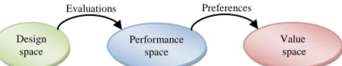
Design theory usually defines three spaces that gather concepts on which the design process will work: the de-sign, the performances and value spaces. The design (or decision) space is a combination of the possible values of design parameters (components, connection and main component parameters in the case of architecting). The performance (or objective) space is an N-dimensional space composed of performance attributes (e.g. mass, cost, availability). The value space is built taking into account the performance space and the preferences of decision-makers. While the divergent phase works on the design space exploration, the convergent phase works on performance and on value space assessment.
MOSIM’12 - June 06-08, 2012 - Bordeaux - France
Figure 1 - Different spaces in design theory
2.1 The creative phase
During the creative phase of the architecture design pro-cess, different design alternatives must be imagined. Generally, two strategies to tackle the creative process can be distinguished: derivative design and innovative design.
2.1.1 Derivative design
Derivative design is based on the reuse of existing sys-tems architectures (old products, competitors…). Adap-tations of the architecture are often necessary due to new functions, new performance requirements or change of value perception (e.g. growing importance on environ-mental aspects on decisions). These adaptations are done by technology changes and by “light” rework of the ar-chitecture (e.g. addition or removal of a component). The main interest of such an approach is that it maximizes the reuse of architecture concepts and consequently de-creases the development costs, delays and risks. On the other hand, the possibilities of innovation and of strong product/system improvements are limited as the process only explores a small part of the whole design space.
2.1.2 Innovative design
Innovative design is a completely opposite strategy. It focuses on the identification of a large design space and on its exploration. Contrarily to derivative design, it makes abstraction of previously designed systems and offers great opportunities of radical innovations that can lead to disruptive improvements of the product.
In the field of optimization, whatever the evaluation and decision methods are, derivative design can be viewed as a local optimization process for which previous architec-tures are used as starting points whereas innovative de-sign is based on a global optimization process working on the whole design space.. Although local optimization is a more straightforward and faster process, global op-timization processes generally find better optimum, no-tably in discrete problems, as they do not stick to local optima. For this reason, this approach will be used in our method.
Several methods were developed to enable innovative design dealing with system architectures. Many of them rely on the tuning of the component parameters of an architecture (De Tenorio et al. 2008) or on the substitu-tion of components by others working on a given archi-tecture (Gubitosa et al. 2009; Scaravetti 2004). It finds the best combination of components for a given structure of the system, but doesn’t find the best architecture for the system under consideration.
Some recent methods, known as formal design synthesis methods, overcome this limitation by considering the structure of the system architecture as an optimization
criterion. They generally rely on design rules that define the compatibility between objects (components or func-tions). Most of them only consider components and search structures of components that respect some rules (Seo et al. 2003; Bolognini et al. 2007; Alber & Rudolph 2004). Some of these methods also consider functions to generate a product physical architecture (Kurtoglu & M. I. Campbell 2009) using explicit functions-to-components rules.
Techniques based on matrixes (Bryant et al. 2005; Holey 2010; Condat 2011) are also able generate design alter-natives for system architectures. In these approaches, the problem and its solutions are described using matrixes (function-to-component, function-to-function, compo-nent-to-component…) that permit to represent one-to-one relations between the objects of the problem. An algorithm then combines the matrices information to compute feasible solutions (generally by use of con-straint programming) and to build new matrixes repre-senting the arrangement of components and functional allocations.
2.2 The decisional phase
During the decision phase, design alternatives that were synthesized during the creative phase have to be evaluat-ed. This evaluation is performed by comparing the set of criteria of each alternative and selecting the best/preferred ones..
Evaluations of alternatives make the link between the design space and the performance space and can be done by two different means (not mutually exclusive).
The first mean is to acquire the performances of a given design alternative and to ask to experts to assess it on a given criteria.
The second mean is to numerically compute performance indicators or data. For this, recent M&S (Modeling and Simulation) means are useful as they enable the computation of per-formances for complex systems. From the in-formation contained in a model and using the associated semantic, simulation tools are able to compute attributes and/or to simulate the behav-ior of the system.
Once the performances have been computed, decisions can be made to select the preferred design alternative(s). As it is very seldom that an alternative dominates all others on all criteria, it is necessary to make trade-offs between the different considered criteria. These trade-offs require to make a link between the performance space and the decision space via preferences of the stakeholder.
A simple way to support the decision process is to use the Pareto optimality definition (Pareto 1896) to high-light most interesting alternatives based on the declared criteria. Nevertheless, this approach is often unable to filter sufficiently the solutions and enable the designer to analyze all of them. Other methods can be used to sup-port the decision. They are known as Multi-Criteria De-cision Analysis (MCDA) methods and have been
devel-Design space Performance space Value space Evaluations Preferences
oped in the field of Operational Research (see Figueira et al. 2005 for a review). These methods support the deci-sion process by analyzing the performances of the alter-natives taking into account the decision-maker prefer-ences Introducing preferprefer-ences in the decision generates solutions that are closer to the designers’ expectations.
2.3 Optimization
Optimization processes is a coupling of both creative and decisional phases. The optimization process is able to discover the optimal solution(s) of the problem given a search space, constraints and objectives without testing every possible solution.
Evolutionary algorithms (genetic algorithms, genetic programming, Particle Swarm Optimization, …) are proved to be robust and reliable ways to find optimum solution(s) for continuous, discrete and hybrid problems. These techniques are based on the same principle: gener-ating a population of solution(s), assessing them and generate a new population based on the best elements of the previous population. By repeating this process until convergence, the population individuals progressively move to optimal zones of the design space. These ap-proaches are heuristics i.e. the optimality of the found solutions cannot be proved mathematically.
As a majority of industrial problems do not consider only one objective, a multi-objective optimization (MOO) process has to be used. This kind of process takes into account several objectives in the definition of best architectures. For instance, the NSGA-II algorithm (Deb et al. 2000) uses the Pareto dominance definition to select alternatives based on several optimization objec-tives.
The method described in the next section supports both divergent and convergent phases of the architecture de-sign process.
3 PROPOSED APPROACH
The proposed method aims at exploring the design space in order to find the most interesting solutions of the de-sign problem. For this, we developed an algorithm that synthesizes system architectures based on a functional architecture, system interfaces, a library of components and a set of design rules. This algorithm is able to create several design alternatives thanks to this knowledge and random mechanisms.
Using this algorithm to generate the whole set of design alternatives would be very costly as the combinatory of the problem is huge. To overcome this problem, an evo-lutionary algorithm is used to iteratively modify the ini-tially synthesized solutions and explore the design space. The exploration process is guided by the performances of the alternatives and, thus, limited to the most interest-ing zones of the design space.
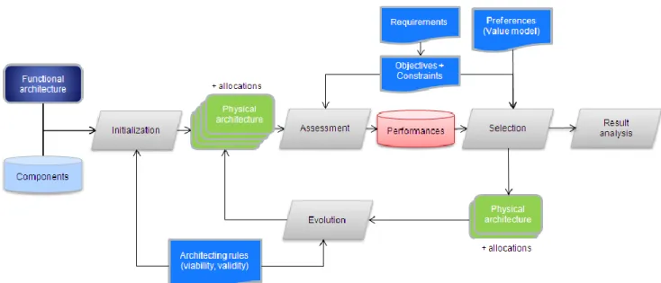
The process (Figure 2) is composed of the following activities that will be detailed in the following para-graphs:
- Initialization: initial design alternatives are generat-ed basgenerat-ed on the description of the problem
- Assessment: the performances of the architectures along each criterion are computed
- Selection: the best architectures are selected based on their performances.
- Evolution: evolution mechanisms are applied to best architectures to create a new population
- Result analysis: at the end of the process, results are analyzed by designers to make a decision.
MOSIM’12 - June 06-08, 2012 - Bordeaux - France
3.1 Problem modeling
First, some characteristics of the problem must be mod-eled to permit the execution of the process.
The method is based on a custom meta-model which contains the concepts needed for the representation of architecture aspects (components, connections…) as well as decision aspects (criteria, objectives…). This meta- model will be used to build the problem model.
3.1.1 System boundaries modeling
System boundaries must be modeled to define the system properties with its environment. The system is modeled as a block with ports. System boundaries ports have flows (e.g. altitude data, electrical power for a given sys-tem…), a direction (input, output or bidirectional) and a multiplicity to indicate the number of simultaneous con-nections that can be made with the port.
3.1.2 Function modeling
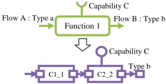
The functions of the system must be modeled to permit the synthesis of valid architectures. They are modeled as classes with input and output flows. Flows are typed (e.g. “altitude data” is of type “raw data”). Function can have required capabilities (e.g. “computing capabili-ties”). These capabilities are used to determine the va-lidity of component chains to fulfill the function i.e. a chain of function can realize a function if it provides the required capabilities. Function classes can also be en-riched by any attribute that would be necessary for veri-fication of constraints or performance evaluations (e.g. a function safety level).
Figure 3 – Illustration of a function
3.1.3 Component modeling
Components that can be used by the algorithm to synthe-size architectures are modeled as classes with ports and are grouped into a component library. Ports have a flow type and a direction. Components can have provided capabilities that are used to check validity of component chains. Component models can be enriched by any at-tribute (e.g. component mass) and can be linked to any model (e.g. a behavioral model) that will that would be necessary for analysis.
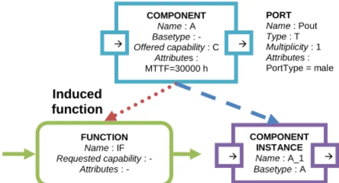
A component cannot be put directly in an architecture. Instead, an instance of it must be created. The compo-nent instance inherits from the compocompo-nent properties (ports, capabilities and attributes). Also, when a
compo-nent instance is added to an architecture, instances of its induced functions are added to the system functions. The maximum number of component instances in an archi-tecture can be limited by the user.
Figure 4 – Illustration of a component, its induced func-tion and an instance of it
3.1.4 Decision modeling
The quality of alternatives must be defined. The user can define criteria, e.g. “mass”, that will be linked to an evaluation module (see 3.3). These criteria are then linked to objectives and/or constraints. Objectives are declared with a criteria and an optimization direction e.g. “minimize mass”. Constraints are declared using a crite-rion, a comparator, a performance threshold and a criti-cality (see 3.4.3) e.g. “mass must be less than 60kg with criticality 2”.
Figure 5 – Examples of criteria, performance, constraint and objective
3.2 Population initialization
The process starts with the definition of an initial popu-lation constituted by a predefined number of different architectures (individuals). Architectures can be explicit-ly defined by the system designers but an algorithm can also create valid architectures based on the model previ-ously defined. This algorithm relies on the functional architecture, on the component library, on the system interfaces and on design rules.
The viability rule defines in which condition two ports can be linked by a connection. The default rule checks that the two ports have inverse directions (in/out), com-patible types and do not exceed their multiplicity (the maximum number of connections that can be made to/from it). The rule can be extended by adding a condi-tion on an attribute of the ports. For instance, the user
COMPONENT Name : A Basetype : - Offered capability : C Attributes : MTTF=30000 h FUNCTION Name : IF Requested capability : - Attributes : - Induced function PORT Name : Pout Type : T Multiplicity : 1 Attributes : PortType = male COMPONENT INSTANCE Name : A_1 Basetype : A FUNCTION Name : F1 Requested capability : C Attributes : MaxAdmissibleMTTF = 1e9/h in1 in2 out
can define a “port type” attribute (male/female) and state that the two ports must also have different port types. The validity rule defines in which condition a chain of components is able to realize a function. The default rule checks that the capabilities required by the function are contained in the set of capabilities offered by the compo-nents of the chain. Also, this rule checks that the chain can be connected to the sources, if any, and sinks of the function (see Step 2.1). As for the viability rule, the va-lidity rule can be extended based on the functions and components attributes.
Using these two rules, the synthesis algorithm is able to generate viable and valid architectures in accordance with the following process:
Step 1. The algorithm treats each function sequentially
in a backtracking manner. For this, the algorithm first orders system functions so that a function supplying an-other one is placed after it.
Step 2. The algorithm builds a chain for each function Step 2.1. The algorithm looks for sinks and sources
for the output and input flows of the function. A sink (resp. source) is a system port containing a function output (resp. input) flow or being of same type, or a component containing a function output (resp. input) flow. The chain of components allocated to this func-tion will have to connect to these sinks and sources.
Step 2.2. The algorithm searches chains of
compo-nents that respect the viability and validity rules. For this, the algorithm performs an in-width search of component chains that respect these rules. The com-ponents considered in the chains can be existing component instances or library components that will be instantiated in the architecture. The depth of the search (in other words the length of the chains) is limited to the N+Δ depth level where N is the mini-mal size of possible chains and Δ is a parameter of the algorithm.
Step 2.3. If several chains of components are viable
and valid, the algorithm selects randomly one of them. All choices are equiprobable.
Step 2.4. The selected chain of components is
im-plemented in the architecture. If the chain contains library components, instances of them are added to the architecture and their induced functions are added to the system functions. The treated function is allo-cated to the component instances. The function input and output flows are added to the port’s flows and/or to the component variables. This information will be used for the detection of sinks and sources for the next treated function.
At the end of this process, all functions are allocated to component instances; ports are linked by connections and contain flows. The architecture model can be used to assess the performances of the architecture.
Figure 6 – Example of function allocation to component instances
3.3 Analysis
The performances of the current population individuals must be evaluated to permit their comparison and their selection. For every attribute, an evaluation mean (per-formance evaluator) must be set up. The models created at the beginning of the process and their associated data can be used to compute performances. The method does not provide guidelines for setting up these evaluation means as they are specific to the attributes being in-volved in the tackled design problem.
3.4 Selection of preferred alternatives
Based on the evaluation of alternatives performances, the “best” alternatives have to be selected in order to gener-ate a new population. For this, two approaches can be used.
Pareto selection process. The first one is a Pareto
ap-proach where alternatives are compared thanks to the Pareto dominance rule i.e. an alternative dominates (is better than) another if it is at least as good on all objec-tives and better on one. This approach permits to obtain the Pareto front of the problem which is very useful in understanding the problem stakes and notably the tradeoffs between objectives.
The algorithm used for this approach is NSGA-II (Deb et al. 2000).
Preference-based selection process. The second
ap-proach is a preference-based apap-proach where preferences of the decision-makers are taken into account during the selection process. For this, the NEMO algorithm (Branke et al. 2009) is used.
Every N iterations, two alternatives are presented to the decision-makers that, based on their performances, must define which alternative is preferred to the other. Indif-ference between the two alternatives can also be stated. Based on this information, the algorithm will compute preference information under the form of Value func-tions and rank the alternatives with respect to their Val-ue. This approach permits to concentrate the search of solutions on the preferred zones of the performance space.
Function 1 Flow B : Type b
C1_1 C2_2
Flow A : Type a
Capability C
Capability C Type b
MOSIM’12 - June 06-08, 2012 - Bordeaux - France
Constraints. Constraints are taken into account by
mod-ifying slightly the dominance relation of both Pareto and preference-based selection process as defined in (K. Deb 2005) i.e. a solution A is said to ''constraint-dominate'' solutions B, if any of the following conditions are true: 1. Solution A is feasible and solution B is not.
2. Solutions A and B are both infeasible, but solution A has a smaller constraint violation.
3. Solutions A and B are feasible and solution A domi-nates solution B (in the Pareto sense or in the preference-based sense)
3.5 Evolution
At this stage, we explore new regions of the design space based on the previous region explorations identified as potentially interesting. For this, genetic operations are applied to the selected alternatives (architectures) to build new ones. We used the 3 genetic operators defined by Holland (Holland 1975): reproduction, mutation and cross-over. Nevertheless, as we do not represent the ar-chitecture as a chromosome, these operators are special-ized to be able to operate on the architecture model.
In our approach, it is important that our genetic opera-tions always ensure the validity of the created soluopera-tions as they take into account the types of involved function ports and component ports. To do that they use the same generative techniques as during the initialization process (viability and validity).
The mutation operator can take different forms. It can replace a component chain by an equivalent one or add/remove redundant component chains.
Cross-over operations are realized by exchanging the chains of the two alternatives every two functional chain. The selected and replaced component chains have a compatible structure that respects the given design rules. All these operations are performed randomly on alterna-tives, functions and component chains.
At the end of this stage, a set of new alternatives and their associated system models are created and added to the new population.
This evaluation-selection-evolution process is iterated until a stop criterion is reached. It can be a predefined number of generations, a minimum Value (satisfying threshold) that must be reached by an alternative or a convergence criterion.
3.6 Results visualization and analysis
The usage of the preference-based selection algorithm enables to gather preference information during the reso-lution process and to focus on interesting and valuable alternatives for the decision-maker.
But even with this process, once the optimization phase is ended, the comparison of the optimal architectures is still a challenge, since the number of alternatives select-ed at this stage is still too important for a manual
analy-sis. For this reason, it may be necessary to filter the final solutions thanks to the application of a preference-based selection process (MCDA method, visual method…).
4 APPLICATION
A tool called SAMOA (System Architecture Model-based OptimizAtion) was developed to implement the method from model creation/import to visualization of results. Using this tool, the method was tested on a sim-plified industrial use-case demonstrator developed to implement the method: the design of an aircraft cockpit. The problem is constituted of 8 functions, 10 instantiable components (screens, computers, cables, networks…) and of a system with 13 ports (systems’ interface, pilots’ interfaces, electrical interfaces).
5 criteria are considered: - Mass of the architecture
- Number of components in the architecture - Part number i.e. number of types of components present in the architecture
- Electrical consumption
- Mean availability time of output functions (functions which does not produce a flow used by other functions)
All these criteria are associated to objectives to be mini-mized (except for availability which must be maxim-ized). No constraints are considered.
The initialization stage permits to find solutions to the problem with various performances (Table 1).
Pop. 0 S y st em mass (k g ) P ar t nu m b er C o m p o n en ts n u mb er M ea n el ec tr ic al co n su mp tio n (W) M ea n A v ai la b ili ty Ti me ( h ) Min 41,4 8 17 450 33322,6 Max 65,4 11 31 678 39023,1 Mean 51,7 10,1 22,7 559,4 35688,2
Table 1 – Performances of synthesized architectures Using the Pareto approach, the algorithm is able to find a set of Pareto-optimal solutions (Table 2).
Pop. 19 Sy st em mass (k g ) P ar t nu m b er C o m p o n en ts nu m b er M ea n el ec tr ic al co n su mp tio n (W) M ea n A v ai la b ili ty Ti me ( h ) Min 36,1 (-12%) 7 (-12%) 15 (-12%) 388 (-14%) 34759,1 (+4.3%) Max 58,7 (-10%) 11 (0%) 28 (-9.7%) 621 (-8.4%) 41956,2 (+7.5%) Mean 46,8 (-9%) 9,3 (-8%) 20,5 (-9.7%) 489,1 (-13%) 38291,3 (+7.3%)
Table 2 – Performances of optimized architectures and comparison to initial architectures performances Thanks to visualization techniques integrated to the tool, it is possible to visualize:
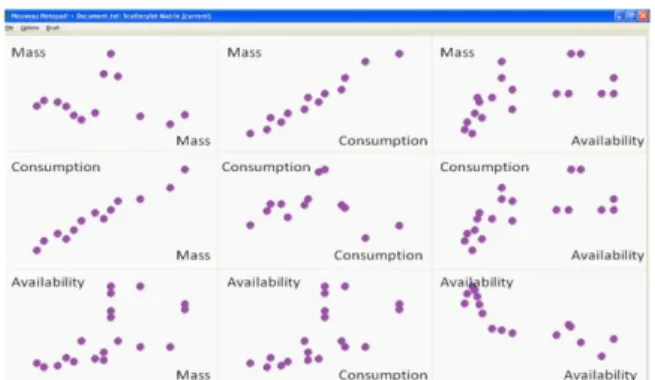
- algorithm progress to monitor the algorithm conver-gence (plot of min-max performances over populations). - solutions as a whole to better understand the problem i.e. correlation between objectives, maximal attainable performances. For this, a scatter-plot matrix permits to see the relationships between performances of each pair of criteria. In Figure 7, one can clearly see the correla-tion between Mass and Electrical consumpcorrela-tion.
- individual solutions to analyze best architectures char-acteristics (physical and functional aspects). For this, architectures are represented as graphs of components or as matrices.
Figure 7 – Scatter-plot matrix view of the final popula-tion in ggobi software (Ggobi 2011)
5 CONCLUSION AND PERSPECTIVES
The main interest of the approach is that it gets rid of the system architectures designed previously for similar sys-tems, thus enabling innovative design. Instead, this method enhances the system architecture design process by enabling the evaluation of numerous design alterna-tives and the selection of the most promising ones. By exploring largely the design space, the chances to get the global optimum architecture (with respect to given de-signer’s preferences) is increased. The method also sup-ports the designer in understanding the problem (correla-tions and tradeoffs) or in eliciting its preferences with respect to the different viewpoints of the system perfor-mances.
The application of the method is particularly suitable for architecture design problems with large combinatorial design spaces as it is able to handle this complexity with limited and simple inputs from the user. In these prob-lems, the number of combinations of components is huge and designers generally censure their creativity to limit this complexity and be able to handle it. Using this method and the associated tool, the designers will be able to formalize the design problem to find the best po-tential solutions to it, leaving computers treating the complexity of the problem. It shall also allow the intro-duction of new technologies in architecture design stud-ies to check whether their use in the new system is perti-nent or not. The introduction of new technologies can improve significantly the performances of systems but often require changing the architecture of the system. The method permits to see quantitatively the
improve-ment of the system performances using the new technol-ogy and thus to deduce if it is worth introducing it and, if so, in which architecture.
One important thing to note about the method is that its purpose is not to make architecting activities by comput-ers but to allow the architects to have tendencies on the interesting regions of the design space. These tendencies will then serve as a base for further studies of the inter-esting architectures and for negotiations with other de-sign teams or with industrial partners.
Some potential extensions of the method can be high-lighted.
First, for problems with many constraints on the struc-ture of the system (e.g. a function must be allocated to at least two computers), this approach is not efficient. In-deed, as constraints are only considered at analysis and selection phases, a lot of generated solutions will be structurally not acceptable. In order to overcome this problem, structural constraints (i.e. constraints which do not require component data to be checked) could be tak-en into account during the initialization and evolution phases.
Secondly, in order to maximize the reuse of models by the designers, interfaces with standard modeling lan-guages (SysML (OMG 2010), AADL (SAE 2009), …) should be designed. This will permit to model the prob-lem (or at least part of it) reusing existing models (e.g. functional architecture model) and to gather final results (architectures) without having to build again architecture models.
Finally, the possibility to group similar architectures in clusters will be studied. Indeed, in upstream design phases, designers are often looking for design patterns or architecture concepts instead of a particular architecture. Additionally, selected architectures should be robust i.e. a slight modification of the architecture should not de-crease significantly the system performances. Thus, by selecting robust design patterns, this risk can be elimi-nated.
Currently, the added-value of the method to the current design process has not been assessed as it needs to be applied to the real case. Nevertheless, the system design-ers we collaborate with already see it as an efficient mean to detect interesting solutions in the preliminary stages of the design.
REFERENCES
Alber, R. & Rudolph, S., 2004. On a grammar-based design language that supports automated design generation and creativity. In J. Borg., F. Farrugia, & K. Camilleri, eds. Knowledge intensive design
technology IFIP TC5. Springer Netherlands, p. 19.
Bolognini, F., Seshia, A.A. & Shea, A.K., 2007. A Com-putational Design Synthesis Method for MEMS Using COMSOL. In COMSOL Users Conference
MOSIM’12 - June 06-08, 2012 - Bordeaux - France
Bryant, C. et al., 2005. A computational technique for concept generation. In Proceedings of IDETC/CIE. pp. 24–28.
Condat, H., 2011. Model-based automatic generation
and selection of best architectures. Master thesis,
Technical University of Munich.
Deb, K. et al., 2000. A fast elitist non-dominated sorting genetic algorithm for multi-objective optimization: NSGA-II. In Parallel Problem Solving from
Na-ture PPSN VI. Springer, pp. 849–858.
Figueira, J., Greco, S. & Ehrgott, M., 2005. Multiple
criteria decision analysis: state of the art surveys,
Springer Verlag.
Ggobi, 2011. Ggobi website. Available at: www.ggobi.org.
Gubitosa, M. et al., 2009. A system engineering ap-proach for the design optimization of a hydraulic active suspension. In Vehicle Power and
Propul-sion Conference, 2009. IEEE, pp. 1122–1130.
Holey, V., 2010. Toward the prediction of multiphysic interactions using MDM and QFD matrices.
De-sign, p.1-11.
Holland, J., 1975. Adaptation in natural and artificial systems.
INCOSE, 2007. INCOSE Systems Engineering
Hand-book,
Kurtoglu, T. & Campbell, M.I., 2009. Automated syn-thesis of electromechanical design configurations from empirical analysis of function to form map-ping. Journal of Engineering Design, 20(1), p.83– 104.
NASA, 2007. NASA System Engineering Handbook, Pareto, V., 1896. Cours d’economie politique.
Scaravetti, D., 2004. Formalisation préalable d’un
pro-blème de conception, pour l'aide à la décision en conception préliminaire. PhD thesis, Ecole
Natio-nale Supérieure d’Arts et Métiers de Bordeaux. Seo, K. et al., 2003. Toward an automated design
meth-od for multi-domain dynamic systems using bond graph and genetic programming. Mechatronics, p.1-21.
Tenorio, C. De, Armstrong, M. & Mavris, D., 2008. Ar-chitecture Subsystem Sizing and Coordinated Op-timization Methods. 26th International Congress