HAL Id: hal-01838589
https://hal.laas.fr/hal-01838589
Submitted on 13 Jul 2018
HAL is a multi-disciplinary open access
archive for the deposit and dissemination of
sci-entific research documents, whether they are
pub-lished or not. The documents may come from
teaching and research institutions in France or
abroad, or from public or private research centers.
L’archive ouverte pluridisciplinaire HAL, est
destinée au dépôt et à la diffusion de documents
scientifiques de niveau recherche, publiés ou non,
émanant des établissements d’enseignement et de
recherche français ou étrangers, des laboratoires
publics ou privés.
Design and simulation of 10 GHz VCO based on RF
MEMS solenoid inductor
Nizar Habbachi, Hatem Boussetta, Mohamed Kallala, Ali Boukabache,
Patrick Pons, Kamel Besbes
To cite this version:
Nizar Habbachi, Hatem Boussetta, Mohamed Kallala, Ali Boukabache, Patrick Pons, et al.. Design
and simulation of 10 GHz VCO based on RF MEMS solenoid inductor. IEEE International
Multi-Conference on Systems, Signals & Devices (SSD’18), Mar 2018, Hammamet, Tunisia. 5p.
�hal-01838589�
Design and simulation of 10 GHz VCO based on RF
MEMS solenoid inductor
Nizar Habbachi
Microelectronics and Instrumentation Laboratory, Faculty of Sciences of Monastir, University of Monastir, 5000
Monastir, Tunisia, habbachinizar@yahoo.fr
Hatem Boussetta
Institut Prépratoire aux Etudes d’Ingénieurs de Monastir, Rue Ibn Eljazzar - 5019 Monastir Tunisia, and he is with Microelectronics and Instrumentation Laboratory, Faculty
of Sciences of Monastir, University of Monastir, 5000 Monastir, Tunisia,
hatem_boussetta@yahoo.fr Mohamed Adel Kallala
Military Research Centre, Tunis, and he is with Microelectronics and Instrumentation Laboratory, Faculty
of Sciences of Monastir, University of Monastir, 5000 Monastir, Tunisia,
Adel.kallala@gmail.com
Ali Boukabache
Laboratory for Analysis and Architecture of Systems, CNRS , LAAS, 7 avenue du Colonel Roche, 31077 Toulouse, France, and he is with the University of Toulouse,
1077 Toulouse, France, aboukaba@laas.fr
Patrick Pons
Laboratory for Analysis and Architecture of Systems, CNRS, LAAS, 7 avenue du Colonel Roche, 31077
Toulouse, France, ppons@laas.fr Kamel Besbes
Center for Research on Microelectronics & Nanotechnology, CRMN Sousse TechnoPark, BP 334 Sahloul Sousse, Tunisia, and he is with Microelectronics
and Instrumentation Laboratory, Faculty of Sciences of Monastir, University of Monastir, 5000 Monastir, Tunisia,
kamel.besbes@fsm.rnu.tn
Abstract— This paper reports the design and simulation of 10
GHz VCO based on RF MEMS solenoid inductor. We have investigated four RF MEMS solenoid inductors using FEM software. Indeed, we have studied the effect of different dielectric substrate and metallic coil on inductors responses. Higher performances are obtained using copper coil and SU8 dielectric substrate: SRF= 20.8 GHz, Qmax= 60.9, and L = 2.6 nH at 10 GHz. Therefore, we have designed and investigated a cross-coupled CMOS VCO based on the best RF MEMS solenoid inductor. The obtained results show a wide tuning range TR = 46% comprised between 10 GHz and 14.6 GHz, and a good linearity of frequency variation in response of control voltage. Moreover, output signals present a high voltage upper than 1.2 V and a low phase-noise PN = -102.37 dBc/Hz at 1 MHz. In addition, the spectral analyze show that output peak power reaches 14.56 dBm at a center frequency of 10 GHz and the second harmonic is less than -58.9 dBm. These results prove high spectral signal ability of the proposed RF MEMS CMOS VCO at 10 GHz.
Keywords-MEMS; VCO; solenoid inductor; wide band; high spectral;
I. INTRODUCTION
Technological progress provides a fundamental basis for RF applications evolution and remains the essential brick of all its advances. Furthermore, MEMS technics are increasingly used in RF synthesizer for higher performances resonators embedded in oscillators' architecture.
The first oscillators use quartz resonator in order to generate a high spectral signal. The operation frequency of quartz oscillators ranges from a few kHz to tens of MHz. There are several oscillator using quartz in their architecture: Pierce oscillator [1], Overtone oscillator [2], Miller oscillator [3], and Colpitts oscillator [4]. Their operating frequency is limited by the resonant frequency of quartz and they could be integrated in PLL architecture leading to compensate the phase noise error.
In this paper, we are interested by wide band VCO operating at 10 GHz using RF MEMS solenoid inductor. In the first paragraph, we have explored the effect of different materials on RF MEMS solenoid inductor. We have used two types of substrate: dielectric resin SU8 and conventional silicon. We have analyzed the performances at each case using two different metal core: gold and copper. In the second paragraph, we have integrated the most performant inductor in the VCO architecture. Moreover, we have analyzed the time domain outputs for the two extremities control voltages and we have presented the frequency responses of our VCO.
II. PERFORMANCES ANALYZES OF RF MEMS SOLENOID INDUCTORS:
In this part, we expose the results of four solenoids inductors having the same geometrical dimensions and different materials for the substrate and the core metal. The objective is to study the RF responses of these inductors for high
frequency range comprised between 100 MHz and 100 GHz, and we integrate the best performances' inductor in a 10 GHz VCO architecture.
The Fig. 1 presents the 3D perspective of 5 turns RF MEMS solenoid inductor with the appropriate dimensions on top and front view:
(a)
(b) (c)
Fig. 1 RF MEMS solenoid inductor (a) 3D perspective (b) top view (c) front view with detailed dimensions.
A. Dielectric SU8 substrate:
The two first inductors use a dielectric substrate "SU8 resin" and they are formed by two different metallic core: gold and copper. The SU8 resin is a low loss dielectric resin tanδ = 0.04 presenting a very low permittivity ε= 2.9, and it is appropriate for high frequency domain [5-8]. Moreover, the employed metals having high electric conductivity such: σ = 41.106 S/m
for gold and σ = 57.106 S/m for copper.
The performances of different RF MEMS solenoid inductors are determined by equations below:
(1) (2)
0.1
1
10
100
-20
-15
-10
-5
0
5
10
15
20
Induc
tanc
e (nH
)
Frequency (GHz)
Gold core
Copper core
(a)0.1
1
10
100
0
10
20
30
40
50
60
70
Q
ual
it
y
f
ac
tor
Frequency (GHz)
Gold core
Copper core
(b)Fig. 2 Inductor performances in response of frequency variation (a) inductance value (b) quality factor.
The inductance value versus frequency is presented in Fig. 2a. As we can see, in two cases the inductance curves are almost identical. The inductance value is stable for a large frequency range and it is close to L = 2.6 nH until 10 GHz and the resonant frequency is higher than 20.8 GHz.
The Fig. 2b illustrates the quality factor variation in response of frequency. It is clearly seen that copper core quality factor is higher than gold core. Indeed, the quality factor is limited by the serial resistance of the inductor core and when the coil conductivity rises the resistance weakens. The maximum value of the quality factor occurs at 5.7 GHz and we obtain Qmax= 60.9 for copper coil and Qmax=49.4 for gold coil.
B. Conventional silicon substrate:
The third and fourth inductors are superposed on a conventional silicon substrate having a low conductivity σ = 3 S/m and possess a high relative permittivity Ԑ = 11.2. We have also used two different metal for the inductor core: gold and copper. The inductors performances results in response of frequency are joined in Fig. 3:
0.1
1
10
100
-3
-2
-1
0
1
2
3
4
Induc
tanc
e (nH
)
Frequency (GHz)
Gold core
Copper core
(a)0.1
1
10
100
0
2
4
6
8
10
12
14
16
18
Q
ual
it
y
f
ac
tor
Frequency (GHz)
Gold core
Copper core
(b)Fig. 3 Inductor performances in response of frequency variation (a) inductance value (b) quality factor.
The Fig. 3a shows a good similarity of inductance curves in response of frequency in two cases: gold core and copper core. In addition, the resonant frequency is upper than 12 GHz and but it is lower than the two first cases using SU8 substrate. Once more, the Fig. 3b shows that the quality factor of copper coil Qmax= 16.2 is higher than Qmax=14.4 of gold coil.
The Table 1 resume the different results of four designed RF MEMS solenoid inductors:
TABLE I. PERFORMANCES RESULTS OF DIFFERENT RFMEMS
SOLENOID INDUCTORS
Substrate metal Core quality factor Maximum value at 10 GHz Inductance frequency Resonant Dielectric:
SU8 Copper Gold 49.4 at 6.1 GHz 60.9 at 5.7 GHz 2.6 nH 20.8 GHz
Conventional:
Silicon Copper Gold 16.2 at 0.8 GHz 14.4 at 0.8 GHz 3.5 nH 12.8 GHz
These results demonstrate the importance of the SU8 substrate and the copper metal in the design of high performances RF MEMS solenoid inductors.
III. DESIGN AND SIMULATION OF 10GHZ RFMEMSVCO:
A. VCO architecture:
The design and the simulation of the VCO is realized using ADS software and TSMC RF CMOS 0.13 µm standard technology. We have used the second solenoid inductor based on copper core and SU8 substrate in order to design the 10 GHz VCO. The Fig. 4 presents the architecture of complementary cross-coupled VCO and the dimensions of PMOS and NMOS transistors:
Fig. 4 Cross-coupled CMOS VCO using RF MEMS solenoid inductor.
B. Time domain analyzes:
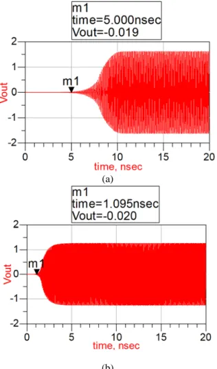
The time domain response of the designed VCO is investigated for two-extremity voltages controls Vctrl = 0V and Vctrl = 0.5V. Indeed, the rise of Vctrl value lead to the expansion of oscillation frequency and influences the time domain response of the VCOs. It is important to evaluate the reaction of VCOs at two Vctrl limits in order to analyze the output voltage signals behavior at two frequencies extremity. The Fig. 5 illustrates two output signals behaviors in response of time from 0 s to 20 ns:
(a)
(b)
Fig. 5 Time domain VCO performances at: (a) Vctrl=0V (b) Vctrl=0.5V.
The Fig. 5a presents the response of the VCO for the initial control voltage Vctrl=0V. As we can see, the start-up time reaches 5 ns and the steady state time is 11 ns. In Fig. 5b, when the control voltage increases Vctrl=0.5V the start-up time and the steady state time decrease and reaches respectively: 1 ns and 5 ns. These results demonstrate the amelioration of the speed response of our VCO in responses of Vctrl.
Moreover, we have zoomed the output signals as shown in Fig. 6:
(a)
(b)
Fig. 6 Behavior of output voltage signals at: (a) Vctrl=0V (b) Vctrl=0.5V.
The Fig. 6a show symmetrical sinusoidal oscillations with a period of 0.1 ns and a peak voltage of 1.62 V at Vctrl=0V. At the last Vctrl=0.5V (Fig. 6b), the period reaches 0.07 ns and the output peak voltage remains greater than 1.2V (the supply voltage of the VCO). These results reveal a wide variation of oscillation frequency with high voltage sinusoidal output signals.
C. Frequency response analyzes:
The phase noise presents a critical parameter for RF designer and they need to decrease its value as much as possible for high spectral frequency synthesizer. Consequently, we have extracted the phase noise value and the output spectrum at 10 GHz. Moreover, we have investigated the frequency responses of our VCO as illustrated in Fig. 7:
(a)
(b)
(c)
Fig. 7 Frequency analyzes (a) tuning range (b) phase noise response (c) spectral output voltage harmonics.
The Fig. 7a shows a good linearity of the frequency variation in response of control voltage. In addition, the frequency band is comprised between 10 GHz and 14.6 GHz leading to a wide tuning range of TR = 46%. Moreover, as we can see in Fig. 7b, the phase noise is about -102.37dBc/Hz at 1 MHz of offset frequency. This result proves that our VCO could be efficient for low phase-noise wireless system. Moreover, the peak
output power of our VCO reaches 14.56dBm at a center frequency of 10 GHz and the peak of the second harmonic is less than -58.9dBm (Fig. 7(c)). This result shows high spectral signal ability at 10 GHz.
IV. CONCLUSION:
Different RF MEMS solenoid inductors are designed using two substrates and two metals cores. The best performances' solenoid inductor are achieved with a dielectric SU8 substrate and a copper coil. The obtained results show a high quality factor that reaches Qmax= 60.9, a wide resonant frequency
band upper than 20 GHz, and a stable inductor value L = 2.6 nH until 10 GHz. Furthermore, the selected RF MEMS solenoid inductor is integrated in VCO architecture for wireless communication systems operating at 10 GHz. The time domain and the frequency investigations of RF MEMS VCO show a high spectrum output signals and wide band tuning range upper than TR = 46%.
REFERENCES
[1] Bahadur, H.; Parshad, R.; "Modified Pierce oscillator circuit"; Proceedings of the IEEE Volume: 66, Issue: 2 Publication Year: 1978. [2] Tsuzuki, Y.; Adachi, T.; Ji Wen Zhang; “Fast start-up crystal oscillator
circuits”; IEEE International Frequency Control Symposium, 49th Proceedings of the 1995.
[3] Rodriguez- Pardo, L.; Farina, J.; Gabrielli, C.; Perrot, H.; Brendel, R.;" Miller Oscillators for High Sensitivity Quartz Crystal Microbalance Sensors in Damping Media", IEEE International Frequency Control Symposium and Exposition, 2004.
[4] Xiaojuan Ou; Wei Zhou; Hongbo Kang; “Phase-noise Analysis for single and Dual-mode Colpitts Crystal Oscillators”; IEEE international frequency control symposium and exposition, 2006.
[5] Pinon, S., Diedhiou, D. L., Gué, A. M., Fabre, N., Prigent, G., Conédéra, V., ... & Boukabache, A. (2012). "Development of a microsystem based on a microfluidic network to tune and reconfigure RF circuits". Journal
of Micromechanics and Microengineering, 22(7), 074005.
[6] El Gmati, I., Calmon, P. F., Boukabache, A., Pons, P., Fulcrand, R., Pinon, S., ... & Besbes, K. (2011)." Fabrication and evaluation of an on-chip liquid micro-variable inductor". Journal of micromechanics and
microengineering, 21(2), 025018.
[7] Habbachi, N., Boussetta, H., Boukabache, A., Kallala, M. A., Pons, P., & Besbes, K. (2016). "Tunable MEMS capacitor: influence of fluids".
Electronics Letters.
[8] Habbachi, N., Boussetta, H., Boukabache, A., Kallala, M. A., Pons, P., & Besbes, K. (2016). "Fabrication and modeling of a capacitor microfluidically tuned by water". IEEE Electron Device Letters.