Publisher’s version / Version de l'éditeur:
Vous avez des questions? Nous pouvons vous aider. Pour communiquer directement avec un auteur, consultez la première page de la revue dans laquelle son article a été publié afin de trouver ses coordonnées. Si vous n’arrivez pas à les repérer, communiquez avec nous à PublicationsArchive-ArchivesPublications@nrc-cnrc.gc.ca.
Questions? Contact the NRC Publications Archive team at
PublicationsArchive-ArchivesPublications@nrc-cnrc.gc.ca. If you wish to email the authors directly, please see the first page of the publication for their contact information.
https://publications-cnrc.canada.ca/fra/droits
L’accès à ce site Web et l’utilisation de son contenu sont assujettis aux conditions présentées dans le site LISEZ CES CONDITIONS ATTENTIVEMENT AVANT D’UTILISER CE SITE WEB.
Internal Report (National Research Council of Canada. Division of Building
Research), 1973-01-01
READ THESE TERMS AND CONDITIONS CAREFULLY BEFORE USING THIS WEBSITE.
https://nrc-publications.canada.ca/eng/copyright
NRC Publications Archive Record / Notice des Archives des publications du CNRC :
https://nrc-publications.canada.ca/eng/view/object/?id=e5b2de5b-97ce-4c4a-96d0-634e8c0b06af https://publications-cnrc.canada.ca/fra/voir/objet/?id=e5b2de5b-97ce-4c4a-96d0-634e8c0b06af
Archives des publications du CNRC
For the publisher’s version, please access the DOI link below./ Pour consulter la version de l’éditeur, utilisez le lien DOI ci-dessous.
https://doi.org/10.4224/20358814
Access and use of this website and the material on it are subject to the Terms and Conditions set forth at
Performance tests of the smoke control system of the Arts Tower of
Carleton University
NA TIONAL RESEARCH COUNCIL OF CANADA
DIVISION OF BUILDING RESEARCH
PERFORMANCE TESTS OF THE SMOKE CONTROL SYSTEM OF
THE ARTS TOWER OF CARLETON UNIVERSITY
by
G. T. 'I'arnu r a and C. Y. Shaw
ANAL YZED
Internal Report No. 405 of the
Division of Building Research
Ottawa August 1973
THE ARTS TOWER OF CARLETON UNIVERSITY by
G. T. Tamura and C. Y. Shaw
PREFACE
The Division has been studying the factors affecting the migra-tion of smoke through multi-storey buildings for the past several years, and has developed a number of approaches to the control of smoke in the event of fire. Buildings incorporating these concepts are now being constructed and it is of great value to be able to determine how they perform. This report pre sents the re sults of one such serie s of te st s that were made on the Arts Tower of Carleton University in Ottawa. The Division is very appreciative of the co-operation of the Carleton University, in permitting and assisting in carrying out these tests.
The results of these tests, and other similar ones, will provide design and application data that can only be obtained by such direct experience. This kind of information is needed as a basis for rational building code regulations and for the de sign of systems that will meet the code requirements.
This report is a private record of what was done and of the re su.It s that were obtained: the information will ultimately be published in a form that better suits the needs of designers and code officials.
Ottawa N. B. Hutcheon,
r
,
,
2-L each smoke shait at top mechanical floor connected to horizontal metal ducts which terminate at the exterior walls a few feet
below roof level
g. no smoke damper at ground floor
h. smoke damper operated by pneumatic motor
Operation (Figure 3)
a. automatic actuation of smoke control system with either a smoke detector or pull alarm at each floor
b. perimeter system to 100 per cent outside air
c. interior system to 100 per cent outside air, flow diverted to two elevator shafts by means 'of dampers in duct work located at the top mechanical floor
d. shutdown of return fan
e. closure of dampers in branch ducts of return system on the fire floor
f. smoke dampers at the top and fire floor opened
g. smoke damper on each floor except the one at the top of smoke shaft can be opened independently from the control panel in basement
h. alarm to central heating plant
Other Provisions
a. communication system hand sets and loud speakers b. elevators key operated switch for independent service c. alarm system
d. annunciator panel
FIRST SERIES OF TEST
The fourth floor (second typical floor) was selected as a fire floor. No fire or simulation of fire was attempted. The smoke control system was operated manually rather than automatically. The fourth storey was designated as a fire floor. Measurements were conducted under the following te st conditions.
Test Nos.
1 air handling systems operating normally, 2 air handling systems shutdown,
3 air handling systems shutdown smoke dampers open at the top and fourth floor,
4 floor space pre ssurization with both the interior and perimeter supply fans smoke dampers open at the top and fourth floor basement and ground floor air system shutdown,
セN
5 floor space pressurization with a perimeter supply fan and elevator shaft pressurization with an interior supply fan smoke dampers open at the top and fourth floor basement and main floor air systems shutdown.
Figure 4 illustrates the floor space pressure pattern for the various test conditions. Outdoor temperature was 25°F. With the systems shutdown (Test No.2) the neutral plane of the building is located at the floor level of the nineteenth floor. With the system under normal operation (Test No.1) the building is pressurized with a
resultant lowering of the neutral plane to the floor level of the tenth storey corresponding to a pressurization of 0.13 inch of water. The second floor (main floor) was pressurized to a greater extent with pressurization of 0.26 inch of water.
Test No. 3 was conducted with the air handling systems off and with the smoke shaft in operation. The building pressures decreased by 0.02 inch of water caused by the exhaust of inside air to the outside through the smoke shaft. The pressures in the fourth storey where the
smoke dampers were open were slightly lower than the storeys above and below.
Test No.4 was conducted with the floor spaces pressurized with the perimeter and interior supply systems and with the smoke shaft in operation. The total rate of outside air supply was 55,000 cfrn. with 34,900 cfrn. supplied by the perimeter system and 20, 100 cfrn. supplied by the interior system. The amount of floor space pressurization obtained was 0.31 inch of water.
Test No.5 was conducted with the floor spaces pressurized with the perimeter supply system and the two banks of elevator shafts with
the interior supply system. The smoke shaft was also in operation. The total rate of outside supply air was 70,500 cfrn. with 30,300 cfrn. supplied by
the perimeter system and 40,200 cfrn supplied by the interior system.
The higher rate of total flow compared with that of Test No.4 was caused by a substantial increase in the flow of the interior supply fan. This
was probably due to the lower resistance to flow through the elevator shafts as compared with that of the interior supply air duct system. The amount of building pressurization obtained was 0.49 inch of water.
At the winter design temperature on a 2 1/2 per cent basis of -10°F for Ottawa the total stack effect is 0.70 inch of water. The pressurization
required to balance the building pressures and outside pressures at ground level is about 0.35 inch of water and the corresponding flow rate required is estimated to be 50,000 cfrn , In so far as the flow requirement for building pressurization is concerned the smoke control system appears to be more than required.
The objective of the smoke control system is to create a flow pattern across the fire floor enclosure such that the direction of flow is into the fire floor and from the fire floor into the smoke shaft. Pre s-sure differences across the fourth floor enclos-sure were, therefore, measured for all tests and the results are given in Table 1. With the air systems off (Test No.2) pressures of the fourth floor were higher
-4-by 0.010 inch of water than those of the NW stairshaft and the north and south elevators at the aam e level. Pressures of the third, fourth and fifth floors were about the s am e , The direction of flow is, therefore, from the fourth floor into the elevator and stairshafts. With the air
system off, the flow pattern is caused mainly by stack action as the wind velocity at this time of test was low. With the smoke shaft in operation (Test No.3) pressures of the fourth floor were lower than pressures of the third and the fifth floors by 0.002 inch of water. Pressure differentials across the SE stairwell and the north and south elevator shafts at the fourth floor were zero. Pressures in the NW stairshaft, however, were lower than those of the fourth floor by 0.009 inch of water. With the exception of the NW stair shaft, the direction of flow was into the fourth floor enclosure and out through the smoke shaft.
For Test No.4, with only the floor spaces pressurized and with the smoke shaft in operation, pressures of the fourth floor were lower than pressures of the third and fifth floor by 0.004 inch of water. Pressures in the elevator and stair shafts, however, were lower than those of the fourth floor indicating a flow of leakage air from the
fourth floor into these shafts. It is expected that the leakage flow into the shafts occurred on all floors that were pressurized as well as on the fourth floor with outflow of air from the shafts to floors that were not pressurized such as the ground, basement and the top mechanical floor and also to outside. Leakage openings in the shaft walls on the floors that were pressurized would permit indirect pressurization of the vertical shafts, whereas, leakage openings floors that are not
pre ssurized or which communicate to outside would re sult in a decrease in the pre s surization of the shaft s , The re sultant pre s sur ization of the vertical shafts would therefore depend on the relative sizes of these leakage openings. As the elevator shafts are located in the core of the building, with most of the leakage openings in the shaft enclosure open to the floor areas, negative pressure differentials across the
elevator shaft walls were substantially lower than those across the walls of the stair shafts which are located adjacent to the outside walls.
Opening the stair door of the fifth floor introduced flow of air from this floor into the stair shaft and decreased the adverse pre s sur e differential across the stair door of the fourth floor from -0.038 to -0.003 inch of water. Opening the stair doors of both the fifth and third floors further reduced the adverse pressure differentials to zero.
With both the floor spaces and the elevator shafts pressurized, and with the smoke shaft in operation (Test No.5), pressures of the third and fifth floor we r e higher than those of the fourth floor by 0.015 inch of water. Pressures in the elevator shafts were higher than those of the fourth floor by 0.055 inch of water. As in Test No.4, however, pressures
Flow velocities through openings of sm.oke dam.pers of the fourth floor were m.easured with a deflecting vane type anem.om.eter during
Test Nos,3, 4 and 5. The flow rates calculated from. these m.easure-m.ents are as follows:
Sm.oke Shaft CFM NE SW Com.bined Test No. 3 - Air system. off 317 333 650 Test No.4 - Floor space pressurization 1090 827 1900 Test No. 5 - Floor space and elevator 1670 1100 2770
shaft pre s surization
These readings indicate that the rates of flow in the sm.oke shaft appeared to be considerably lower than expected.
SECOND SERIES OF TEST
A second serie s of te st was conducted to obtain additional inform.ation on the perform.ance of sm.oke shafts under the following conditions:
Test Nos.
1 - air handling system. off,
2 - floor space pressurization with both interior and perim.eter supply fans, sm.oke dam.per at the top of sm.oke shaft open,
3 - sam.e as Te st No. 2 with the addition of sm.oke dam.pe rs open at the fourth floor.
Outside tem.perature was 65° F with variations in wind speeds of 8 to 15 m.ph from. the south westerly direction.
Figure 5 shows that with the floor spaces pressurized and with the sm.oke dam.per open only at the top (Test No.2), the am.ount of pressurization was approxim.ately 0.25 inch of water. With sm.oke dam.pers also open at the fourth floor (Test No.3) the am.ount of pressurization was decreased by approxim.ately 0.02 inch of water. Flow rates through the supply air duets were not m.easured during these te st s , The am.ount of pre s surization was lowe r for this te st com.pared with that of the first series of test (0.31 inch of water). This was probably caused by different flow rates through the interior supply system. for the two te sts as this system. is a variable volum.e type.
Table II gives the results of pressure m.easurem.ents across the fourth floor enclosure for the second series of tests. Cornpa r i son of m.easurem.ents for Test No. 3 of Table II with those for Test No. 4 of Table I, both with the floor spaces pressurized and sm.oke dampers open at the fourth floor and at the top, indicate s agreem.ent in the m.easured flow directions across the fourth floor enclosure.
During Test. No. 3 the bottom. exit door of the SE stair shaft was opened to the outside. Adverse pressure differential across the stair door at the fourth storey increased from. -0.014 to -0.100 inch
-6-of water. When the SE stair door at the fourth floor was opened as well as the bottom exit door, a flow of air was noticeable at the opening from the fourth floor into the stair shaft.
Flow velocities through the smoke shaft were measured with a hot wire anemometer. During Test No.2, with floor spaces pressurized and smoke dampers open at the top only, flow velocities were measured near the top of the smoke shaft by removing the access door in the horizontal metal duct of the smoke shaft. Because of difficulty in reaching inside
the duct, accurate measurements of air velocities were not possible. Random measurements were made, however, and the average duct air velocity calculated. Based on these measurements, the rates of air flow were 2200 and 1700 cfm for the SW and NW smoke shafts. These flow rates represent the rates of air leakage flow into the smoke shaft. Examination of the smoke shaft construction indicated that the gasketted
smoke shaft dampers are relatively air tight although the wall construction appears to be relatively leaky particularly at joints between the concrete block walls and the concrete floor slabs as well as between the concrete block and the poured concrete walls.
Pre s sure differentials across the walls of the smoke shafts were measured a.t several levels. These are given below.
Smoke Shaft Floor NE SW 1 (basement) 0.114 4 -0.081 -0.075 5 -0.073 -0.076 9 -0.080 -0.082 17 -0.100 -0.090 22 -0.138 -0.120
Note: Readings in inch of water; floor space pressure as reference. As the first floor (basement) was not pressurized, a positive
pressure differential was obtained across the shaft at this floor. Pressure differentials increased with increase in height of shaft. This was
probably caused by the reduction of pressures inside the smoke shaft due to various pressure losses. Measurements of pressure losses were obtained directly and are as follows:
Smoke Shaft
NE SW
5th to 22nd floor 0.070 0.065 22nd floor to top of smoke
shaft 0.060 0.065 5th to top of smoke shaft 0.130 0.130 Note: Values are in inch of water
From the flow and pressure measurements, the leakage area in the walls of the SW smoke shaft that begins at the third floor (first typical floor) was estimated. Assuming an average pressure differential across the smoke shaft of 0.088 inch of water and leakage flow of 2200 cfrn , the total leakage area was calculated to be 3. 1 sq. ft or approximately
0.15 sq ft per floor which represents 7 per cent of the opening of a smoke damper. Based on an inside wall area per floor of 116 sq ft this represents a leakage area of L 3 sq ft per 1000 sq ft of smoke
shaft wall area. Comparison of this value with that of 0.26 sq ft per 1000 sq ft of wall area for an unplastered 13 -jn , brick wall indicate s that the walls of the smoke shaft in this building are very leaky.
Measurements of pressure drop inside the SW smoke shaft indicated that half of the total pressure drop (0.065 inch of water) occurred from the 5th to the 22nd floor and the remainder from the 22nd floor to the top of the smoke shaft. The relatively large pressure drop near the top of the smoke shaft probably occurred at the entrance and at the two 90 -degree bends of the horizontal metal duct connecting the top of the smoke shaft to the out s ide at the exte rio r wall s , The
large pressure drop inside the smoke shaft from the 5th to the 22nd floor was probably caused by the rough interior surface of the smoke shaft, the constriction at each floor level caused by the concrete floor slabs that have openings of only 4.6 sq ft compared with 7.2 sq ft between floors, and the leakage flow into the smoke shaft.
With smoke dampers open at the fourth floor as well as at the top, flow rates at the top of the smoke shafts were 1960 cfrn for both the NE and SW smoke shafts. Measured flow rates through the open
smoke dampers at the fourth floor were 552 cfrn for the SW smoke shaft and 812 cfrn for the NE smoke shaft. The leakage flow through the
walls of the smoke shaft would then be 1400 and 1150 cfrn re spectively, significantly higher than the flow rates through the open smoke dampers.
Pressure differentials across the walls of the smoke shaft were as follows: Smoke Shaft Floor NE SW 1 (basement) 0.146 4 5 -0.042 -00051 9 -0 0048 -0.057 17 -0.079 -0.081 22 -0.115 -0 0120
-8-Comparison of these values with those of Test No.2 with the top smoke dampers opened indicates that a reduction in pressure differentials occurred when smoke dampers at the fourth storey were also opened. Increase in the rate of exhaust air through the smoke shaft can cause a
reduction in the floor space pre s sure s (see Figure 5, approximately 0.02 inch of water) and an increase in pressure losses inside the smoke shaft. Both effects will result in a reduction in the pressure differentials across the walls of the smoke shaft.
Measurements of the pressure losses inside the smoke shaft for Te st No. 3 are as follows:
Smoke Shaft
NE SW
5th to 22nd floor 0.085 0.070 22nd floor to top of smoke
shaft 0.070 0.070
5th to top of smoke shaft O. 155 0.140
Higher pressure losses inside the smoke shaft compared with those of Te st No. 3 were probably caused by an increase in the rate of air flow inside the smoke shaft.
Building pressurization for Test No.3 was approximately 0.24 inch of water which is the maximum available pre ssure differential across
the smoke damper at the fourth storey. Actual pressure differential across the smoke shaft was 0.04 to 0.05 inch of water. The difference in the two values can be attributed to the pressure losses inside the
smoke shaft which caused a reduction in the venting capacity of the smoke shaft to less than half of that with no pressure losses.
DISCUSSION
Te sts indicated that with the smoke control system in operation and with only the floor spaces pressurized, pressures in the vented floor were reduced but not sufficiently to prevent flow of air from the designated fire floor into elevator and stair shafts. Two factors are involved he r e , the effe ct of floor space pre s surization and the efficiency of the smoke shaft.
Floor Space Pressurization
With floor spaces pressurized, air flows from the pressurized areas to unpressurized areas such as elevator and stair shafts. If there are leakage openings in the enclosure of these shafts which connect to the outside, pressures inside these shafts would be lower than in the floor spaces. This was demonstrated during the tests when the exit door
of the stair shaft was opened to the outside. Pressures in the stair
shaft were lower than those in the floor spaces by approxitnately 0.10 inch of water; and the floor spaces were 0.25 inch of water above outside
pressures. If in addition the stair door at the fire floor is also open, substantial flow of smoke into the stair shaft can be expected during a fire emergency.
To prevent this from happening, building pre s surization should be modulated with outside temperature to achieve a balance in pressures between the floor space and the outside at grade level. In this way
potential for smoke spread into the stair shaft can be reduced.
In addition, the stair shaft should be pre ssurized as an added protection and as a means of diluting any smoke that may have entered the stair shaft. The addition of an extra door in the stair shaft between grade and the floor above can also assist in reducing the possibility of stair shaft contamination.
Pressurization of elevator shafts can also prevent smoke flow into them as was demonstrated when both floor spaces and elevator shafts were pre ssurized with the smoke control system of this building.
Efficiency of Smoke Shaft
Tests indicated that the rate of air exhaust through the smoke shaft was not sufficient to decrease pre ssure s in the vented floor below those of the elevator and stair shafts. They also indicated that only one fifth of the available pressure difference acted across the opening of the smoke damper at the fourth floor with the remainder dissipated as pressure losses. The rate of air flow through the open smoke damper was only 35 per cent of the total rate of flow out of the smoke shaft with the remainder through leakage openings in the walls of the smoke shaft. Examination of the construction of the smoke shaft indicate s that the inadequate performance of the smoke shaft was probably caused by the leaky wall construction, the constriction of the passageway of the
smoke shaft at each floor level and by the horizontal metal duct connection between the top of the smoke shaft and outside at the exterior walls.
With the floor spaces pressurized to 0.25 inch of water, adverse pressure differentials across the stair doors were approximately 0.025 inch of water. With the smoke damper open, the total air exhaust rate from the fourth floor was 1360 cfm which reduced the adverse pressure differential by approximately 0.008 inch of water. From these values the leakage area of the floor enclosure is roughly e stirnat ed to be 6. 5 sq ft. Using this value the required exhaust rate to balance pressures across the stair doors is 2400 cfm or almost double the measured exhaust rate through the open smoke dampers.
-10-These tests indicate that for efficient operation srri oke shafts should be constructed in such a way that leakage flow and pressure
losses inside the shaft are rninirrri ze d , Both factors should be considered in the design of a sm oke shaft.
ACKNOWLEDGMENT
The authors wish to acknowledge the contr ibut ion rn ad e by R. G. Evans who assisted in the field tests.
PRESSURE DIFFERENCE MEASUREMENTS ACROSS FOURTH FLOOR ENCLOSURE Test No. Between floors 3 & 4 Between floors 5 & 4 SE Stair-well NW Stair-well South Elevator North Elevator 2 Sy stern off 0 0 0 -0.010 .0.010 ..0.009 3 Sy stern off Smoke Shaft in Operation 4 Floor Pre-ssurization Smoke Shaft in Operation 5 Floor and Elevator Pre s suriza-tion Smoke Shaft in Operation 0.002 0.004 0.015 0.002 0.004 0.017 0 -0.012 -0.014 -0.009 -0.038 -0.036 0 -0.002 0.053 0 -0.002 0.059
Note: Reference Pressure - 4th floor
---TABLE II
PRESSURE DIFFERENCE MEASUREMENTS ACROSS FOURTH
FLOOR ENCLOSURE Te st No. Between floors 3 &: 4 Between floors 5&:4 SE Stair NW Stair South Elevator North Elevator 1 System off 0 0 0 0 0 0 2 Floor Pre-s Pre-surization Smoke Damper Open at Top 0.002
-
.006 -0.022 -0.026 -0.024 -0.009 3 Floor Pre-ssurization Smoke Darnpe r Open at Top and 4th Floor 0.007 0.005 -0.014 -0.017 -0.009 -0.002Note: Reference Pressure - 4th floor
N
-....
-I
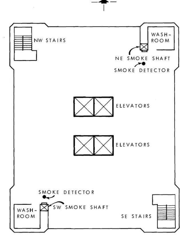
WASH-ROOMセセエnw
STA I RS1
NE SMOKE SHAFT?
SMOKE DETECTOR ELEVATORS ELEVATORS SMOKE DETECTOR NセL
WASH- ROOM SEstaGrウャセセ
FIGURE 2
FLOOR PLAN
/ TO TWO ELEVATOR SHAFTS
u
..--<r SMOKEIJ
LJ--;=---...
セ
-':I",J
Vr
I'" セ.-
....
セ SMOKMセ
J f-
セ
"-...
'-
S HA FTV \
.JI セ....
<,-J
セ ,./ ... i"+-;
iセ .JI セ . /"
...
'--
,...
-"""'
セ セ , . /"
...
セ SUPPL , . / "--
FROM J セ..
, / セ"-... セ I NDU
t;
セ "-セ セ"-....
/t'
J I...
./ ... セ セ r-セJ '
..
. / ...I-t-
'--
... セJ
..
. /....
セ-1:;
...
./ ... セ .JI...
. /..
. / -,r-.
'--
....
... セ セ セセr-.
'-
iiセ
セ....
セイ
セ セ-
f-セ ..-r+
セ-
f-.--1f' .... ./ ....r+
"-セ|eB
...
...
セセ ... FIR E.:
.... GZGZGZZGZGセ ... セZZNZ..
ZNZNセ セセ ;;. セ...
, ." •• : :.0° "0 •• セ..
" r+
"--
セ..
,/ ....f-+-..
... f+ E S HA FT NOTE: Y A I R PERIMETER DOWN. DA M PE RS RETURN FA NS SHUT CTION UNITS IN BRANCH RETURN DUCTS ON FIR E FLOOR CLO SED.FLOO R
./
'"
FIGURE 3
OPERATION OF SMOKE CONTROL SYSTEM
\
22
20
18 16 14 1 2 1 0 8 6 4 2 1 Bo
OUTDOOR TEMPERATURE, 25F
TEST NO.3
AIC SYSTEM
SHUTDOWN
SMOKE SHAFT
OPERATING
\
\
TEST NO.2
AIC SYSTEM
SHUTDOWN
\
\
\
TEST NO. 1
TEST NO.4
AIC SYSTEM
FLOOR SPACE
NORMAL
PRESSURIZA TIO N
TEST NO.5
ELEVATOR SHAFT
AND FLOOR SPACE
PRESSURIZA TIO N
v E
PRESSURE
o .
1
0.2
0.3
0.4
0.5
0.6
PRESSURE, INCH OF WATER
FIGURE 4
FLOOR PRESSURES VS BUILDING HEIGHT (FIRST SERIES
23M 22
20
1 8 1 6セide
14 \PRESSURE 1 2\
1 0\
8
\
6\
4\
\
2\
1 B-¥
'"
TEST NO.2FLOOR SPACE PRESSURIZATION SMOKE DAMPER OPEN AT TOP
Oセ
/ TEST NO.3
FLOOR SPACE PRESSURIZATION SMOKE DAMPERS OPEN AT TOP AND 4th FLOOR
OUTDOOR TEMPERATURE, 65°F
M ⦅ N セ N ,.__. .
---,.---r---y-.
,
o
o .
1
0.2
0.3 0.40.5
PRESSURE, INCH OF WATER