HAL Id: hal-02066082
https://hal.laas.fr/hal-02066082
Submitted on 13 Mar 2019
HAL is a multi-disciplinary open access
archive for the deposit and dissemination of
sci-entific research documents, whether they are
pub-lished or not. The documents may come from
teaching and research institutions in France or
abroad, or from public or private research centers.
L’archive ouverte pluridisciplinaire HAL, est
destinée au dépôt et à la diffusion de documents
scientifiques de niveau recherche, publiés ou non,
émanant des établissements d’enseignement et de
recherche français ou étrangers, des laboratoires
publics ou privés.
Compact Planar Integrated Rectenna for Batteryless
IoT Applications
Alexandru Takacs, Abderrahim Okba, Hervé Aubert
To cite this version:
Alexandru Takacs, Abderrahim Okba, Hervé Aubert. Compact Planar Integrated Rectenna for
Bat-teryless IoT Applications. European Microwave Week (EuMW), Sep 2018, Madrid, Spain.
�hal-02066082�
Compact Planar Integrated Rectenna for
Batteryless IoT Applications
A. Takacs
#, A. Okba
#, H. Aubert
# # LAAS-CNRS, UPS, INPTToulouse, France
[email protected], [email protected], [email protected]
Abstract — This paper addresses a new topology of compact
rectennas in which the rectifier is integrated directly on the radiating surface. The rectenna is designed for wireless power transmission or microwave energy harvesting application in ISM 900 MHz band and exhibits a very good measured conversion efficiency (>25%) on a non-optimal load (10kΩ) for very low microwave power densities (>0.18 µW/cm2). The measured DC voltage (>330 mV for microwave power density of at least 0.22 µW/cm2) obtained from this planar rectenna is in the range of the cold turn-on/start-up voltage of modern commercial off-the-shelf DC-to-DC boost converters and power management units. The proposed rectenna is also very compact: its physical surface (10.5 x 6 cm2) is only 5% of the square wavelength at the operating
frequency (860 MHz).
Keywords — wireless power transmission, microwave energy
harvesting, rectenna, internet of things.
I. INTRODUCTION
The rise of the Internet of Things (IoT) applications faces to a new challenge: how to power efficiently an enormous number of wireless sensors, intelligent tags, and devices? Nowadays, the use of a battery is almost a standard but, the topic of the self-powered/batteryless devices excites from longtime the scientific community and becomes recently an industrial reality for emerging innovative start-up and companies [1][2]. One solution to implement self-powered and/or batteryless devices is to use a wireless power transmission approach: an intentionally microwave transmitter (energy shower) will energize at distance a rectenna module (rectifier + antenna). The energy shower should operate in the ISM bands and is then subject to regulations. ISM 868/915 MHz band provides a good trade-off in terms of free-space losses (fixing the maximum operating range of such a system) and wavelength (fixing the size of receiving antenna of the rectenna module). Many rectenna designs operating in the ISM 868/915 MHz band were proposed in the past with a focus mainly on the measured intrinsic performances (e.g., efficiency, harvested DC power, etc.) [3]-[5]. From an industrial point of view, a successful rectenna design for IoT applications should be compact, low-profile and low-cost. The size of the rectenna module is determined mainly by the receiving antenna. Electronic devices should be also integrated with the antenna, e.g., the rectifier including its matching circuit, the Power Management Unit (PMU), the energy
storage element, etc. But with the same goal in mind: keeping the overall structure as compact as possible.
This paper addresses the design in the ISM 868/915 MHz band of a compact rectenna using a miniaturized flat dipole antenna with the rectifier circuit directly integrated on the radiating surface of the antenna. To the authors’ best knowledge, there are very few designs integrating the rectifier into radiating element at such low frequencies. In [6] the rectifier and the corresponding matching circuit are integrated in the ground plane of a patch antenna designed at 1.96 GHz but they are not integrated in the patch surface itself. Very recently, V. Palazzi et al. [7] reported a compact rectenna using an annular slot with a wire-connected multiband-rectifier positioned on the back-side of the antenna.
Our proposed innovative topology is described in Section II while the experimental results obtained with the manufactured prototype are presented and discussed in Section III.
II. RECTENNA TOPOLOGY AND DESIGN
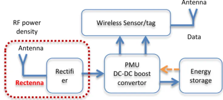
A typical topology for an IoT compatible wireless sensor/tag is sketched in Fig.1. From a practical point of view, if a compact planar structure is desired, the main design objective is to integrate all the functions/electronics (e.g., rectifier, PMU, energy storage, wireless sensor/tag, etc.) into the same Printed Circuit Board (PCB). The size of the overall structure is then mainly fixed by the size of the antenna operating at lowest frequency.
Fig. 1. Sketch of the typical topology of a wireless sensor/tag for an IoT scenario Rectifi er Wireless Sensor/tag Energy storage PMU DC-DC boost convertor RF power density Data Rectenna Antenna Antenna
As design requirements, we target a compact and fully planar rectenna with optimized performances in the ISM 868/915 MHz band. This rectenna should be able to power a standard DC-to-DC boost convertor and PMU (such as, e.g., BQ25504 device [8]) for incident electromagnetic (EM) power densities around 1 µW/cm2. Thus, the rectenna should provide an output DC voltage greater that the cold start-up voltage of such PMU (approximately 330 mV for the BQ25504 device) on a high impedance load (typically > 9kΩ, corresponding to the PMU input impedance) with the highest efficiency. The topology of the proposed 2D compact planar integrated rectenna is shown in Fig. 2 with the 3D rectenna topology.
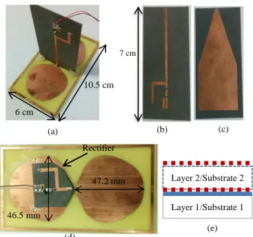
Fig. 2. The manufactured rectennas: (a) the 3D version of the rectenna
combining a flat dipole antenna (surrounded by a rectangular ring) with a rectifier; (b) top view of the rectifier before the mounting of the lumped devices; (c) bottom view of the rectifier; (d) top view of the 2D rectenna and (e) cross sectional view of this rectenna (the continuous blue line corresponds to the metal layer while the dotted red lines indicate the metallic parts of the rectifier.
The rectenna consists of a flat dipole antenna (surrounded by a rectangular ring) integrated with a rectifier using a Schottky diode. The metal layer of the antenna is in (mechanical and electrical) contact with the bottom metal layer of the rectifier. The selected antennas in this frequency band are mainly based on dipole [3]-[5] or annular slot topologies [7]. The patch antennas are impractical in ISM 868/915 MHz band due to the large size. Flat dipole antennas topologies were selected in the past mainly for their broadband and/or multiband behavior [3]-[4]. We selected this topology here because of (i) its broadband behavior that allows operating efficiently in the ISM 868 MHz (Europe) and 915 MHz (USA/Japan) bands and, (ii) the large metal surface of the radiating element that allows integrating the rectifier and eventually other electronic devices. The flat dipole can be miniaturized (the size for operating at the targeted frequency is reduced compared with one of the standard flat dipoles) by
adding an external ring/loop properly designed (see Fig.2). In our case, the size was reduced by 25% (from to 14 x 6 cm2 to 10.5 x 6 cm2). The topology of the rectifier (with the dimensions of microstrip lines) and corresponding ADS simulation model are shown in Fig. 3.
Fig. 3. Rectifier topology and associated ADS simulation model
The rectifier is composed of a series HSMS2850 diode from Avago, a shunt capacitor (100pF) and a resistive load (10kΩ). This rectifier was previously designed, fabricated and characterized in our Laboratory in the framework of a research project with UWINLOC company [2]. An impedance matching circuit combining a short-circuited bend stub with a 30 nH inductance (Coilcraft) was used in order to match the impedance of the rectifier at 900 MHz. The rectifier was fabricated on Ro5870 substrate (thickness: 0.787 mm, relative permittivity: 2.3, dielectric loss tangent: 0.0012) and optimized to operate efficiently for low electromagnetic input power (less than -15 dBm).
III. EXPERIMENTAL AND SIMULATION RESULTS
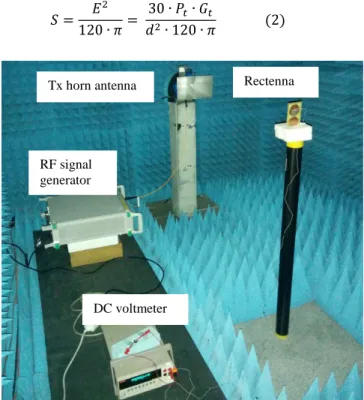
The experimental setup positioned in an anechoic chamber (to prevent any interferences or undesirable multipath effects) shown in Fig. 4 was used to characterize the rectenna. A microwave signal generated from the Anritsu MG3694B generator is injected at the input of a transmitting (Tx) horn antenna through a coaxial cable. The horn antenna illuminates the rectenna under test, positioned in the far-field region of the Tx antenna, with a linearly-polarized E-field. An automatic acquisition routine is implemented in Labview software from National Instruments to speed-up the acquisition process. The harvested DC voltage is then measured by using a DC multimeter. The DC power can be derived from the measured DC voltage as long as the load is known. The efficiency η (in %) of the rectenna can be computed by using the following expression: 𝜂𝜂 =𝑃𝑃𝑃𝑃𝐷𝐷𝐷𝐷 𝑅𝑅𝑅𝑅∙ 100 = 𝑃𝑃𝐷𝐷𝐷𝐷 𝑆𝑆 ∙ 𝐴𝐴𝑒𝑒𝑒𝑒𝑒𝑒∙ 100 = 4 ∙ 𝜋𝜋 ∙ 𝑃𝑃𝐷𝐷𝐷𝐷 𝑆𝑆 ∙ 𝐺𝐺𝑅𝑅∙ 𝜆𝜆² ∙ 100 (1)
where 𝑃𝑃𝐷𝐷𝐷𝐷 is the harvested DC power, 𝑆𝑆 is the incident electromagnetic power density, 𝐴𝐴𝑒𝑒𝑒𝑒𝑒𝑒 is the antenna effective area, 𝐺𝐺𝑅𝑅 is the gain of the (rectenna’s) antenna and 𝜆𝜆 is the free-space wavelength of the illuminating electromagnetic wave at the operating frequency. The electromagnetic power density S can be computed as a function of the E-field
Layer 1/Substrate 1 Layer 2/Substrate 2 47.2 mm 46.5 mm Rectifier (d) (e) 7 cm (a) (b) (c) 6 cm 10.5 cm
effective value 𝐸𝐸 (V/m) on the antenna surface. This value is derived from microwave power Pt injected to the input port of
the transmitting horn antenna (gain 𝐺𝐺𝑡𝑡) positioned at a distance 𝑑𝑑 from the rectenna, as follows:
𝑆𝑆 =120 ∙ 𝜋𝜋 = 𝐸𝐸2 𝑑𝑑30 ∙ 𝑃𝑃2∙ 120 ∙ 𝜋𝜋 (2)𝑡𝑡∙ 𝐺𝐺𝑡𝑡
Fig. 4. Experimental setup used to characterize the manufactured
rectenna.
The flat round antenna was fabricated on a low-cost FR4 substrate (substrate thickness: 0.8mm, relative permittivity: 4.4, dielectric loss tangent: 0.02). As shown in Fig. 5(a), the simulated (HFSS) -10 dB bandwidth of the antenna is between 845 MHz and 1.25 GHz and consequently, covers the ISM 868/915 MHz bands. For comparison purposes the reflection coefficient at the antenna input with and without the rectangular ring are depicted in Fig. 5(a).
We can observe that the ring increases the bandwidth and allows reducing the size of the antenna. Electromagnetic simulations were performed in order to optimize the rectangular ring. The ring perimeter (33 cm) and the distance between the ring and flat dipole antenna were adjusted in order to: (i) minimize the lowest operating frequency and (ii) increase the frequency bandwidth. The radiation pattern is close to one of the half-wavelength dipole with a simulated gain of 2.2 dBi in the -10 dB bandwidth (845 MHz-1.25 GHz). A prototype composed by a flat dipole antenna (enclosed by a rectangular metallic ring) and a compact printed taper were measured. The experimental results reported in Fig. 5(b) validate the frequency bandwidth predicted by the electromagnetic simulations.
The fabricated rectenna (see Fig. 2 d) was characterized by using the experimental setup shown in Fig. 4. The measured DC output voltage delivered by the manufactured rectenna on a non-optimal load of 10 kΩ is reported in Fig. 6. The
maximum DC voltage (471 mV) is obtained at 860 MHz for an incident E-field E=1.28 V/m (0.44 µW/cm2). At 868 MHz, the DC voltage is about 450 mV (0.44 µW/cm2).
Fig. 5. (a) Simulated (HFSS) reflection coefficient (S11 in dB) as a
function of the frequency for the flat dipole antenna enclosed by the rectangular ring (continuous blue line) and without ring (dotted red line); (b) Simulated reflection coefficient of the flat dipole antenna enclosed by the rectangular ring (continuous blue line) and the measured reflection coefficient of the fabricated prototype (dotted red line). The inset shows a photo of the manufactured antenna including the compact taper.
Fig. 6. Measured harvested DC voltage (V_DC) for the manufactured
rectenna (incident E-field: 1.28 V/m, load: 10 kΩ) as a function of frequency.
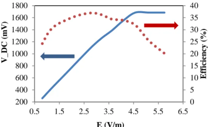
The measured DC voltage and efficiency computed by using eq. (1) are given in Fig. 7 as a function of the incident E-field amplitude. A maximum efficiency of 37% (DC voltage: 1.13 V and DC power: 130µW) is obtained for E=2.88 V/m (2.2 µW/cm2). As compared with the 3D rectenna [9] shown in Fig. 2(a) the 2D rectenna exhibits a little bit lower efficiency, but it is more compact, planar and compatible with a multilayer fabrication process.
-30 -25 -20 -15 -10 -5 0 0.7 0.8 0.9 1 1.1 1.2 1.3 1.4 1.5 S 11 ( d B ) Frequency (GHz) 0 100 200 300 400 500 0.75 0.80 0.85 0.90 0.95 1.00 V_ D C ( m V) Frequency (GHz) -40 -35 -30 -25 -20 -15 -10 -5 0 0.5 0.7 0.9 1.1 1.3 1.5 1.7 1.9 S 11 ( d B ) Frequency (GHz)
Tx horn antenna Rectenna
RF signal generator
Fig. 7. Measured harvested DC voltage (V_DC: continuous blue line, values on vertical left axis) and efficiency (dotted red line, values in % on vertical right axis) as a function of incident E-field (frequency=860 MHz, load: 10kΩ)
A comparison with the recent state-of-art rectennas operating in the same frequency band is reported in Table 1. We selected only designs that use planar antennas and papers that reports experimental results for low-level of incident microwave power density. The state-of-art performances are reported as a function of the estimated microwave power on the rectifier input PRF or as a function of the incident microwave power density S. The size of the antennas/rectennas are reported in cm2 or as function of square wavelength (𝜆𝜆² ) allowing thus a fair comparison between designs operating at different frequencies. As reported in Table 1 the state-of-art designs use: (i) 3D topologies (the rectifier is interconnected with the antenna in a 3D manner as reported in [3]-[4]), (ii) planar but inline (IL) design that typically conducts to a ‘large-size’ design (e.g. [5]) (iii) planar designs where the rectifier is integrated in the radiating element (this work) or connected by wire and positioned on the back-side of the antenna [7] that lead to a more compact designs.
Table 1. Comparison with state-of-the-art designs.
NR : not reported in the paper
* : rectifier connected to the antenna in an orthogonal/3D manner ** : rectifier connected to the antenna by an In Line (planar) connection *** a wire-connected multiband-rectifier is positioned on the back-side of the antenna
It can be observed from Table 1 that the energy harvesting performances of the proposed rectenna are in the state-of-the-art, but with a more compact structure: the antenna/rectenna surface is of 10.5 x 6 cm², that is, only 0.05𝜆𝜆² at 860 MHz. We note also that the efficiencies were measured for optimal loads
while in this work, the load is non-optimal. As a matter of fact, the selected (non optimal) load of 10kΩ allows: (i) to maximize the DC output voltage required for the cold start-up/wake-up of a commercial off-the-shelf DC-to-DC boost converter and, (ii) to simulate the input impedance of the same DC-to-DC boost converter. There is room on our antenna surface to integrate more electronic devices (the metal layer of flat dipole antenna is quite large) in order to obtain a miniaturized autonomous wireless sensor/tag. Moreover, depending on the targeted market, the overall structure can be manufactured either on a multilayer low cost (e.g., FR4) or on low loss (e.g., Ro5870) substrate.
IV. CONCLUSION
An innovative compact rectenna (0.05λ² at 860 MHz) was proposed. It consists of a miniaturized flat dipole antenna with a rectifier which was optimized to operate at low microwave power densities. The rectifier is directly integrated into the surface of the radiating element. The large size of the metal layer of the flat dipole is very convenient for the eventual integration of additional electronic devices. A maximum efficiency of 37% is measured at 860 MHz for the manufactured rectenna with an illuminated electromagnetic power density of 2.2 µW/cm2 only.
ACKNOWLEDGMENT
LAAS CNRS wishes to acknowledge UWINLOC company and the support of the French region OCCITANIE through the research project OPTENLOC.
REFERENCES
[1] https://www.enocean.com/en/technology/self-powered-internet-of-things/
[2] http://uwinloc.com/#innovation
[3] V. Kuhn, C. Lahuec, F. Seguin, and C. Person, “A Multi-Band Stacked RF Energy Harvester With RF-to-DC Efficiency Up to 84%,” IEEE Trans. Microw. Theory Tech., vol. 63, no. 5, pp. 1768–1778, May 2015. [4] C. Song, Y. Huang, J. Zhou, J. Zhang, S. Yuan, and P. Carter, “A high
efficiency broadband rectenna for ambient wireless energy harvesting,”IEEE Trans. Antennas Propag., vol. 63, no. 8, pp. 3486– 3495, Aug. 2015.
[5] S. D. Assimonis, S. N. Daskalakis, and A. Bletsas, “Sensitive and Effi-cient RF Harvesting Supply for Batteryless Backscatter Sensor Net-works,” IEEE Trans. Microw. Theory Tech., vol. 64, no. 4, pp. 1327– 1338, Apr. 2016.
[6] Z. Popovic; E.A. Falkenstein, D. Costinett, R. Zane, “Low-Power Far-Field Wireless Powering for Wireless Sensors”, Proceedings of the IEEE, Vol. 101, No. 6, pp.1397 -1407, June 2013.
[7] V. Palazzi, J. Hester, J. Bito, F. Alimenti, , C. Kalialakis, A. Collado, P. Mezzanotte, A. Georgiadis, L. Roselli, M. M. Tentzeris, ‘Novel Ultra-Lightweight Multiband Rectenna on Paper for RF Energy Harvesting in the Next Generation LTE Bands’, IEEE Trans. Microw. Theory Tech., vol. pp, issue 99 (early access paper)
[8] http://www.ti.com/product/BQ25504
[9] A. Takacs, A. Okba, H. Aubert, “900 MHz Miniaturized Rectenna”, (under soumission)
[10] D. Masotti, A. Costanzo, P. Francia, M. Filippi, and A. Romani, “A Load-Modulated Rectifier for RF Micropower Harvesting With Start-Up Strategies,” IEEE Trans. Microw. Theory Tech., vol. 62, no. 4, pp. 994–1004, Apr. 2014. Ref Freq (GHz) S (µW/cm²) PRF (dBm) 𝝶𝝶(%) Antenna Surface Rectenna Surface [3] 0.9 -15dBm 30 NR NR/3D* [5] 0.868 0.1µW/cm2 1 µW/cm2 44.830 NR NR/IL** [10] 0.9 -10dBm 33 NR NR [7] 0.9 0.1µW/cm2 1 µW/cm2 16 40 11x11cm 2 0.11𝝀𝝀² 11x11cm2 0.11𝝀𝝀² *** This work 0.86 0.21µW/cm² 1.1µW/cm² 2.2µW/cm² 31 35.5 37 10.5x6cm² 0.05𝝀𝝀² 10.5x6cm² 0.05𝝀𝝀² 0 5 10 15 20 25 30 35 40 200 400 600 800 1000 1200 1400 1600 1800 0.5 1.5 2.5 3.5 4.5 5.5 6.5 Effi ci en cy (% ) V_ D C ( m V) E (V/m)