AN AIR IATED STHJCIUfi by
RICH AI BAKER MOITh and
KAY MILTON LOCKHAMR
Submitted in partiaJ £u.ti.Ument or the requirements for the
degree of Master of Architecture in the Department of Architecture at the Massachusetts Institute of Technology.
AN AIR INFLATED STBJCTUIE
by
Richard Baker Morrill
B.A. Macalester College, St. Paul, Minnesota, 1953
B. Arch University of Minnesota, Minneapolis, Minnesota, 1959
and
Kay Milton Lockhart
B.A. University of Minnesota, Minneapolis, Minnesota, 1957
B. Arch University of Minnesota, Minneapolis, Minnesota, L958
Submitted in partiaL fulfillment of the requirements for the
degree of Master in Architecture at the
Massachusetts Institute of Technology
August 22, 1900
Signatures of Authors
Richard Baker Morril
Kay Milton Lockhart
Signature of Head of Department
Lawrence B. Anderson
-1-ABSTRACT
The Masters Thesis in Architecture is normailLy a test of the students acquired knowledge, where he is required to sub-mit a design solution for same pragmatic problem. The thesis project is, in this respect, work essentia.uLy beneficial to the student as a completion to his formal education. The possibility exists in the Masters Thesis, however, for research and investi-gation into fields that indicate some potential architectural use, but which have not been developed. This research could give a direction for further development in the future.
The course of architectural development in the second half of the Twentieth Century is vague and uncertain. A refinement of
now-existing forms and ideas is valuable to a point, but there is a general consensus that the work of the first half of this century left many problems unsolved and many others unrecognized.
There are perhaps three major avenues of further development which have been proposed: A more intensive investigation and explanation
of the structural potentialities of modern ma-terials and the formal potentialities of these structures; a shift of emphasis away from the problems of individual buildings to those of
the total environment, particularly to those of the urban complex; and finally a reintegration of contemporary architecture with our cultural tradition, and a wider acceptance of human as well as formal needs.l
1Student Publications of the School of Design, Editorial, North Carolina State College, Raleigh, N orth Carolina, Vol. 0,
No. 3, May, 19.7.
-2-Research into a facet of architecture that employs
new materials and possib.Ly new structural concepts might not necessarily be an end in itself, but a phase of a subject that would provide some base for a continuing study in the general problems of the system. Others with a common interest could
use this material and continue to broaden its scope so that a fund of knowledge becomes a useful tool for future pragmatic solutions.
Brief investigation into the air structure concept has been motivated by an interest in the potential of new
flexible materials to create long spans when the material is made rigid through air pressure. This economy of material for certain span conditions seems appealing, and with the proper technology perhaps could result in low cost structures for
various uses.
Relatively little investigation of air systems has been done outside of research for specialized functions for the Arnr and Air Force. This imp.Lies a fresh area for research into the structural and architectural implications of air
structures.
This report contains a description of various ex-periments of air structural systems and the observations made from these studies. A proposal is made for a system based
-3-upon the background of experiments completed. The proposal is made only as a graphic presentation of a possible develop-ment and not as a conclusion to the investigation. The
con-clusion reached in this project is better expressed in the sumary, which attempts to catalog the special data developed from this research.
The Authors have initiated a collaboration on this project, in the belief that common interests and pooled effort
can work to mutual advantage. This belief extends to the ex-ploitation of an exchange of ideas that can further enrich and
elaborate an elemental concept.
-4-August 22, .1960
Pietro Be.uschi, Dean
School of Architecture and Pianning
Massachusetts Institute of Techno.ogy
Cambridge
39,
Massachusetts
Dear Dean Be.LLuschi:
In partiaL fulfil.Lment of the requirements for
the degree of Master of Architecture, we hereby submit
this thesis entitled, "An Air Inflated Structure".
iRespectfu.Lly,
RIdchard Baker Morri.L
Kay Milton Lockhart
-5-TA-BkJiE OF CONTENTS
Title Vage . . . .* . . .
Abstract . e . ..* . e
±uetter
of Submitta.. ..Table of Contents . . .
List of Figures and Illustr Acknow.Ledgements . . . . Introduction . . . . . Objective . . . Exposition . . Approach . . . Design Criteria . . . .
Experiments of Air Inflated
Test 1... Test 2 -Test 3 o . . . . Test 4 . * * * * Test 5 o . .- * 4 Test
o
. - * . . . Test 7 . . . . Test 8 - - * * . -0 . . . 0 0 . . . .0* 0
.0
. . .0ations
.0 . .0 . . 0 .0 . 0 0 0 . 0 . . . . 0 .0 . . 0 .0 Syrstems .... 0 .... 0 . . 0 .0 - - . .0 - - 0 0 4 . . 0. . 0 . 4 ,26
8
10
11
13
15
17 2026
30
35
40
44
S S I* 00 0 0 0 0 0
0 0 0 0 0
.
48
Summary on Tests In Woridng Model Form Of Air
Proposal For An Air Inflated Structure . . . . . . . . . . . . 54
A. Selection of Form . ... .. .. 54
B. Membrane
Theory
In Relation To Form . ... 55C.
The Air Inflated System And
Its Static AnaLysis.
57
D. Edge Conditions In
Relation To Tension RIng. . .
63
E. Forces Due To WindLoad . . . . . . .64
F. Joinery, Connections Of Units Together . . . . . 65
G. Mapping Of The Surface . . . . . . . . . . . 66
H. MechanicaL Considerations . . . .
.66
I.
Acoustics . . . . . . . . . . . . . . 69 J. Lighting ... 71K. Membrane MateriaLs
.
... 72
L. Erection Procedures ... 74 Conclusion . . . .75
Bib.Liography . . . . . . . . . 79Appendix .
. . . .
81
-7-LIST OF FIGURtsS AND ILLUSTRATIONS
Figure I, Test
1,
A Circular Inflated Unit . . . . Figure II, Test 2, A Circu.ar Inflated Unit . . Figure III, Photograph of Model, Test 2 ... . . . Figure IV, Photograph of Model, Test 3 . . . . . Figure V, Test 3, A Rectangular Inflated Unit . . Figure VI, Test 4, An Inflated Barrel Vault . . . . Figure VII, Photograph of Model. Test 4 . . . . . Figure VIII, kiiotograph of Model of "Plucha" Surface Figure IA. Test 5, An Inflated "Pkacha" Structure Figure X, 1hotograph of Model. Test 5 . . . . . . FigureXI,
Photograph of Models Test 5 . . . .. .
. . .
17
. . . . . 20 . . . . . 21 . . . 21S.
. .
.26
. .
. .
. 30
.
.
.
* *31
.
. .. .31
.
.
o.
35
*
. .
.
. 36
.
. .
.
36
Figure XII, Test (, Inflated Rectangular and Triangular Units 40 Figure XII, Photograph of Model. Test o . . . . . . . . . . . 41
Figure LIV, hotograph of Model, Test . 41 Figure XV, Test 7, Inflated Barrel Vault, Individual Units . . 44
Figure XVI, thotograph of Model Test 7 . . . . . . . . . . . . 45
Figure
XVII,
Photograph of Model Test 7 .. *.... . ..45
Figure XVIII, Test 8, Inflated Hemispheric Dome . . . , 48
Figure l&1,
k'hotograph
of Model Test 8 . . . . . . . 49Figure XXI, Inflated Unit Cel I Under Hydrostatic
kressure
. . . 60 FigureXXII,
Structure ELementof
Inflated Unit CelLs . . .61
Figure XATTT, Mapping of a "Pucha" Surface Through Location of
Any
rointon
its Surface. . . . . . . . * * 67-9-ACKNOWLJDGENENT
We wish to express gratitude to the following people whose interest, encouragement, criticism and assistance have made presentation of this thesis possible:
Prof. Imre HaLasz, Department of Architecture, Massachusetts Institute of Technology
Prof. Eduardo F. Catalano, Department of Architecture,
Massachusetts Institute of Technology
Dr. Eli Traum, Structura-L Engineer, Visiting Critic Prof. M.J. Holley, Jr., Department of Civil Engineering Massachusetts Institute of Technology
Prof. ALbert G.H. Dietz, Department of Civil Engineering Massachusetts Institute of Technology
trof. Frank J. Heger, Jr., Department of Civil Engineering Massachusetts Institute of Technology
Prof. Robert Newman, Department of Architecture, Massachusetts Institute of Technology
Mr. Walter Netsch, Visiting Critic
Mr. wow. Bird, Birdair Structures, Inc., Buffalo, New York Mr. Wi liam Wainwright, Geometrics, Inc., Cambridge, Mass.
Jo Ann Morrill Beverly Lockhart
-10-INT10DUCTION
Objectives:
The development of an air inflated system or systems that utilizes the concept of double wall construction with air under pressure providing the rigidity for the structure.
Exposition:
Air structures have had a relatively recent development stimulated by the interest given to them for military application and their subsequent use for industry. The initial projects in-volving air structures sought to solve the need of a space en-closure for operating radar equipment that would provide good radio frequency tansmissability. Development and research on air systems for radar installation enclosures proved their feas-ability and they are now widely used for this purpose. Recent developments in rockets and ballistic missiles have used air
structures as housings that could be dismantled readily if launch-ing were imminent. This research under Governmental auspices has been responsible for the acceptance of air structures for industrial use as storage shelters and recently for the enclosure of many
varied activities.
All of the projects mentioned above are air structures of one membrane. The space enclosure is created by increasing the pressure within the total space and the membrane takes its
patterned form due to internal air pressure which stiffens and
-l-stabilizes the membrane. The stresses to the system must be entirely resolved in the membranes, and the desire to maintain a relatively constant stress pattern over the surface has led to development of doubly curved surfaces of revolution. When inflated, this geometry not only establishes a relatively con-stant stress pattern in the membrane, but provides a shape that will best resolve aerodynamic loading.
This type of air structure is simple in concept but is subject to wind and snow loads, and to all kinds of weather conditions the same as any other type of structure and they must be properly engineered to support such loads. The design of these air structures however, is far different from that of a conventional building. They may be considered thin shells, stiffened and stabigized by maintining a sufficient air pressure differential within the structure to pre-tension the "shell" so that it can resist compression loads. As the flexible shell has no bending stiffness, it must resist non-uniform loading by distortion and redistribution of load.
The advantages in using the single membrane type of air structure are:
lightweight and small package size econosry of material
simplified joimary ease of erection structural efficiency
-.L2-
F-The disadvantages are:
total space is secured for inflation ground anchorage is critical
form is limited
(articulation and a sense of scale are not present)
failure in the wall could propagate (could cause panic in a public space) For these reasons and for a desire to broaden the scope of air structures, the authors have decided to work with "cellular" systems onLy. This type of system would utilize a double wall unit that would gain its rigidity by inflation of each unit; these units would then be connected together to form a system. Inflation
pressure would be constant throughout by proper valving between units. This cellular system lends itself to a greater variety
of forms and now offers the possibility of opening up the space by merely providing a roof enclosure. Any failure in one unit would not propagate throughout the system and a damaged unit could be sealed off by special valving, and easily be replaced.
The disadvantages to this structural system would be its greater complexity in number of units, joinery conditions, and perhaps a system that is less efficient structurally than a single wall system.
Approach
1. Investigation of existing developments in air structures in relation to recent developments in membrane and thin shell structures to create an understanding of the static forces that
operate in an air supported system.
2. Determination of the structure in form and surface that satisfied structural requirements within the program re-quirements of the general span and use activity to be considered.
3.
Type of building material feasibly satisfying structuraL requirements. (Inquiry into current trends in industry to produce materials adequate for air inflated systems.)4.
Within the structural system, determine a geometric breakdown that satisfies; structural requirements, estheticcon-siderations, acoustic control, and erection requirements.
5.
General structural analysis including static solutions and details of size and support.b. Construction and erection procedures in relation to program considerations.
7. Record data during design phase.
Note: The approach that has been cataloged above will give a general format to follow in arriving at a design solution. To implement this format the authors wi.l construct models of elements of air systems in the belief that this will give a graphic under-standing of the action of compressed air and membranes in tension under various conditions of material and geometry. The general impressions to these experiments will be noted.
DESIGN CRITERIA
General Bui4ding Type
The choice of a particu.lar structura± system was motivated, as noted, by other than program requirements. Structure does not exist apart from some functional need and though the authors' interest has been primarily in relation to the structure, we do not view this apart from activities to be served, space requirements of use, and considerations for the character of the structure in relation to its use. The logical design sequence emanates from an architectural problem to be solved. This sets limits on the design and also serves as a point of departure for design. In general this will set span and space requirements and create the special design criteria apart from structural considerations that relate to a specific usage.
The advantages of an air system appear more numerous in a long span system mainly because of the economy of weight and material. The economy in terms of financial expenae and construction seems a possibility with further development. One restriction in terms of life of existing fabrics leads to the development of temporary and portable systems. These limitations have suggested uses that couJ.d be well satisfied with an air system.
Certain spectator activities, such as hockey, tennis, swiming, skating, etc., require special span and space require-ments and are affected by seasonal environmental changes. These would benefit from a space enclosure that was economical and
could be changed or removed depending upon seasonal conditions. The program requirements for these activities are we.L defined and concentration can be given to space enclosure, problems of lighting, mechanical requirements, acoustics, and services
that relate directly to the genera.L structural parti.
TEST I - FIGURE I
PLAN
SECTICN
DESCRIPTION
9 eqpal divisions patterned to fonm
a pyramid of 9 sides
lbbberized fabric with taped and
g.Lued joints
Illustration board copression ring MATERIALS
r-TEST .
L. Intention of test - To observe the reaction of compre.ssed
air on a membrane surface and to discover forces at work within
the structural unit.
2. Observations - The first observation was that the continuous
edge member tended to warp decidedly upon introducing air within
the membranes.
This was caused by the force of air on the
mem-branes tending to pul-l inward on the edge member, thus resulting
in a pull that was exerted equal.Uy in all directions due to its
circular shape.
It was also learned that the expected and desired
arching of the membranes never appeared due to lack of rigidity
of the edge member and due to the improper patterning of the
material.
As the somewhat conical shape was maintained under
high and low degrees of tensile stress in the mmbranes, it was
decided that the material should be patterned to the desired
form before air is introduced into the structure. Not only does
it take considerable air pressure to change the shape of an
in-flated unit, if the fabric is relatively non-elastic, but it
introduces unequal tensile stresses over the surface of the
membrane.
3.
Conclusions -
It was decided that a model should be
con-structed employing both a
more rigid frame,
and a pattern
for
-18-the membrane panels that wou.Ld aLLow for a more constant curvature over the structure' s surface. This wou.Ld tend to distribute the tensiLe stress more equa.ly across their surfaces.
-19-
r-TEST 2 - FIGURE II PLAN )1o
SECTION DESCRIPTION8 equal divisions of the surface
patterned to form a circle in plan and curved surface in section once
inflated
MATEMTALS
Ribberized fabric, stitched seams "Celotex" compression frame cotton cord tension lines
IJ
-20-FIGUiE III, IHOTOGRAH OF MODEL, TEST 2
TEST 2
I. Intent of Test - The construction of an air inflated unit with a greater curvature in section which will alLow a more equal distribution of tensile stresses in the membranes than the previous conical shape. To observe forces at work within the structure and to observe the reactions of the tensile
stresses developed in the membranes acting on the points of restraint.
2. Observations - Upon inflation of the structure, it was discovered what had initially forced the rather weak
compres-sion ring of the previous experiment to deform and warp. By supporting the structure at eight equally spaced points a-round the perimeter, buckling of the edge was observed between
each support. The cause for this action of the edge was that as the structure tended to reach a sphere, there was a greater force being exerted on the top and bottom membrane than on the line of the edge. The edge was essentially being pul.Led towards the center of the structure, due to the air pressure working on the two membranes. As the circumference of the structure was being reduced by greater and greater air pressure, the edge was put into compression and once the compression forces
over-came the tensile forces in the membrane, the edge buckled. This
-22-observation resulted in the conclusion that a continuously supported edge member must be employed for proper stability and equilibrium of forces.
we observed that the surface of the two membranes acted far more uniform.ly under air pressure than the prevtous experiment. Even here it was realized that there were tensile
stress concentrations on the membranes and that by increasing
the cross-section curvature of the surfaces we had only lessened these stress concentrations.
3.
Conclusions - A gas such as air operates according to well known physical principles regarding volume and pressure. A sphere is the ideal shape for a container of gas under pressure for it provides a marimum volume in relation to surface area. If a container is rigid and gas in introduced under pressure, the container will maintain its shape until the tensile stresses created in the container by the pressure exceed the structural limits of the container. If the con-tainer is non-spherical, stresses upon the surface of the container will not be equal and deformation will like.ly occur at points where compressive stress taxes place. If the con-tainer is spherical then deformation will on.ly occur when the tensile limit of the containing material is reached.-23-This appears to be a governing factor in flexible air containing units when air under pressure is introduced. A flexible material cannot take compression unless the materiaL has been pretensioned. A flexible unit then, under internal pressure, operates most efficiently if it is spherical, or if it is not spherical, then some external force must be introduced to equilibriate the unequal stress patterns that will occur on the surface of the unit.
It was at this time, after the construction of two air inflated models and observing their conditions and char-acteristics, that the use of this type of structural unit be-came an important consideration. Due to the comparative lightness in weight of an air inflated system, it was decided
that one of the structure's attractive features is its possible portability. The development of the structure could then re-gard small cellular inflated units that could be handled easi.y, assembled easily, and put into operation with a minimum of
specialized work done in the field.
The development of a unit that could be connected with other simi.lar units would precede an experiment which con-cerned itself with the composition of adjacent connecting units. As joinery of component units of a structural system is of a
prime consideration, and the shape of each component and the intersection of units is critical., the geometry of units and a geometric system for these units becomes a major element of the design. Since most previous connections have been done with a zipper method with a high degree of success, the employment of a similar technique seemed feasible. In consideration of the problems involved in connecting circular forms together, cellular units should be constructed of forms that are easier to connect
together with a zipper technique. As a straight line, retangular
edged unit is perhaps most convenient in connection, it was
proposed that a square inflated unit be constructed.
-25-TEST 3 - FIGURE V A
T
B / G N F E DESCRIPTIONS equal divisions patterned *o
form a square in plan and a curved
surface in section once inflated
MATERIAJS
Rtoberized fabric
Stitched and glued seams "Celotex" compression ring
Cotton cord tension lines
-26-C H /
D
PLAN SECTIONTEST
3
i.
Intent of Test
-
The construction of an air inflated unit,
rectangular in plan and curved in section, that would be most
ideal regarding joinery.
To study internal and external forces
of such a unit once inflated, and to devote particular concern
to the eventual structural form of which this unit would be a
part.
2.
Observations
-
The first observation upon inflation of the
unit was the considerable amount of buckling along the edge,
between
AB,
BC, CD, DE, EF, FG, and GH.
Not only was there
buckling on the edge, but there was a noticeable crease that
developed in the material between BC, CF,
FU,
and HB.
This
latter buckling was thought to be caused by improper patterning
in the cut of the material, plus the fact that there exists a
lower membrane stress in the corners of the inflated unit. It
was also noted that there was a tremendous concentration of
tensile stresses in the membranes on both sides of lines BF
and DH.
These stresses were caused by air pressure forcing
the upper and lower membrane apart, and since points B, D, F
and H are the nearest to the center of the unit
(Z
axis), where
the two membranes are the furthest apart, the tensile forces in
the membrane are the greatest at this point. Essentially -what
is happening is that as the air pressure is forcing the top and
-27-and bottom membranes apart, the edge of the unit is being puLLed towards the center of the unit (Z axis), so that the air is forcing the material into a spherical shape. As long as there is continuous restraint around the edge the unit will keep its form, but without this support at the edge, and with sufficient air pressure, the square form will tend to approach a sphere.
3.
Conclusions - Perhaps the most important conclusion. was that the edge of each unit must have a sufficient depth tohave any kind of efficiency in a structural system. It was reasoned that if the surface area of the edge walls were in-creased the tendency to buckle would be lessened because the area of the side walls would more closely approximate the area of the upper and lower membranes, and the air pressure would stress all membranes more equal.y throughout the unit. As the depth of the edge becomes greater, the unit more closely approaches a spherical shape, and as a sphere carries tensile stress in its membrane more equally than any other shape, the increase in depth of the side wall membranes creates a far
greater structural efficiency.
In the consideration of a structural system the
increase in depth of the side wall has some obvious advantages. The greater rigidity between units and a resultant greater
stability to the entire structure would be the first advantage of this change in depth. Secondly, there would be less of a tendency for each unit to deform in buckling, and a far more constant shape would be maintained for the entire structure under lower and higher air pressure differentials. Thirdly, the increase in depth would aid in the transfer of shearing stresses throughout the structure due to the increase of ma-terial in the side walls or "webs" of the structure.
It was decided that a series of experiments and models should be initiated of structural systems incorporating the small air inflated units that have been studied to this time. It was proposed that a simple barrel vault be erected as a linear unit, to study the effects of air inflation in a vault form.
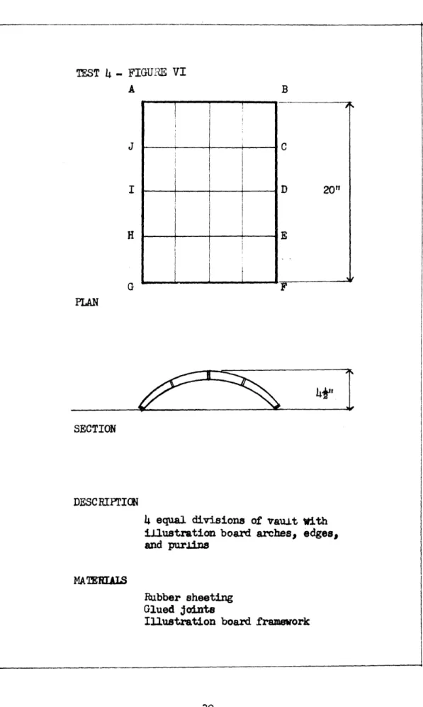
-29-J H G B PLAN
-i
w',
SECTION DESCRIPTION4 equal divisions of vau.t with illustration board arches, edges, and purlins
MATERIALS
Rubber sheeting
Glued joints
Illustration board framework
-30-Z-.
TEST 4 - FIGURE VIFIGURE VII, PHOTOGRAeH OF MODEL, TEST 4
'EST 4
A. Intent of Test
-
The construction of a simpLe barrel vault
using curved inflated arches, to study internal and external
forces at work within such a system.
2.
Observations
-
As air was introduced into the model it was
observed immediately that the rigid edge members at the spring
line of the vault were deformed inwards by air pressure at work
on the upper and lower membranes.
The rigid arch members AB
and GF were also pulled inwards due to the same action of the
two membranes.
The under surface or lower membrane of the vault
showed considerable buckling along its surface, except for the
lines where the rigid arch members restrained the material.
The
resultant action of the air inflation was one of which the entire
vault tended to flatten out; plus, tending to pull in or
fore-shorten the length of the structure.
The rigid edge of lines BIC, CD, DE, EF, etc. were
bowed in due to the action of the upper and lower membranes
pulling on its surface.
The same type of action is happening in
the rigid arches, for if it were not for the rigid purlins that
provide a compression strut, the entire vault would greatLy
fore-shorten. The buckling on the lower membrane is due to air pressure
tending to reduce the membrane curvature, putting this membrane
into compression while the upper surface is put into extreme tension. As the lower membrane is forced from a flat surface to a lesser curvature under air pressure, it will force the material to occupy a smaLler area and obviously produce the resultant buckling.
The tendency for the entire vault to flatten out is due to the unequal tensile stresses in the upper and lower membranes. As there is far greater tension in the upper than in the lower membrane, the edges AG, BF are being puilued up, while the center of each arch is being pushed downwards.
j. Conclusions - This structural system is completely dependent upon the rigidity of a stabilizing frame to keep the vault from
great.Ly deforming and then failing. The use of a separate structure between which an air inflated structure would span, showed disadvantages in lack of structural clarity and port-ability.
A barrel vault with unsupported ends is not an ideal solution for a structure using only air inflated units whether of large units as an arch or smaller units rorming the vault. This vault is only of single curvature and a double curvature is required to eliminate shear and bending stress. Due to these many problems of structural inconsistencies, it was proposed that
the next test be made with a surface of double curvature. In such a surface it was re.t that many of the prob.Lems that were found in this vault would be overcome, and the need for a rigid frame wou.Ld be eliminated.
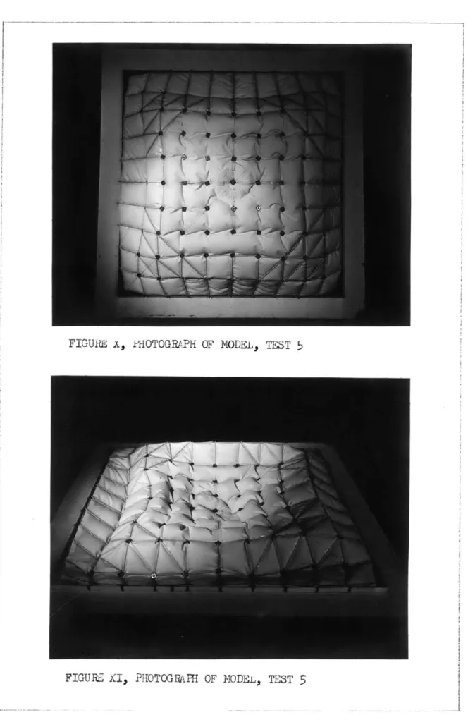
W314-TEST 5- FIGURE II
PILAN
SECTION
DESCRIPTION
"Pucha" surface, 8 divisions to form surface, connections upper and lower membranes at
patterned between points
MATEEALS
lTbberized fabric with vulcanized joints Nut and bolt spacers
FIGURE& x, FHOTOGRAPH OF MODEL, TEST 5
TEST >
.L. Intent of Test - To construct a doub.Ly curved surface that when inflated, could be studied regarding intena.L and externaiL
forces acting on and within such a structure.
2. Observations - The materiaL was pre-patterned to take the form of a "puchal and the upper and lower membranes were connected together at points over the surface of the form. By introducing air into the system it was to be determined if the form would naturally take its shape.
As air was induced into the system the material between point supports began to be put into tension, and as there were no restraining members other than the point connections, the material continued to bililow out. This action continued across
the entire area of the model so that the resultant appearance and form of the model was simi.lar to an air infLated mattress that was exerting a continuous pull on the rigid frame. The action of air inflation is the simple matter of air pressure working on the least surface of resistance, forcing the membranes apart and causing local Duckling in the material and an overall foreshorten-ing of the structure.
To assist this model in taking its form, rigid struts were applied to the surface of the membranes between each point
support. As these were placed at the peripheral edge of the structure and extra supports applied at the four corners of
the model, it was conjectured that this control over the buckling and bending in the system would be sufficient to make the model take its f orm. This proved itself to be fallacious, for the
restraint of the membranes in the peripheral area of the structure had little to no effect upon the central area. This central area
of the modeL (Ref., Figure II) continued to buckle, so that instead of rising into the patterned curvature, this area tended only to pull inwards on the more rigid edge area. The excessive weight of the model should be considered out of scale to the model, but the basic reason for structural failure is the structure's inability to resist shear and bending stresses. Due to a flat curvature
a.long the edge of the form and a reverse curvature that exists in the corners of the "pucha", there is considerable bending and shear stress acting in these areas. his beam action of the structure along the edge, can only be handled by additional
re-inforcement, in order that the structure can be considered stabilized with all forces resolved.
3. Conclusions - What has been observed in this experiment is that a structural system cannot be considered stable and in equilibrium, if the individual units are not also in equilibrium. If
reinforcing struts are introduced between point supports on the
-3b-surface of the membranes, buckling and deformation of the surface are controlled when air is induced into the system. However, reinforcing struts do not necessarily create an
equilibrium condition in the structure as a whole; bending and shear stress must be resolved. The possibility of creating an air structure within this frame of reference exists, but it would be desirable from the standpoint of portability and the development of an ideal or pure air system to create equilib-rium without the need for compression members. to further this idea.l it seems that further study must be given to the individual units. Factors of shape, stability, spacing and size appear extremely vital to the design of the structure. With this in mind the proposal was made to construct a series of sma.Ll units that could be studied by themselves and in tandem with other units.
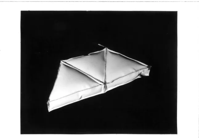
-39-/
PLAN
TYPICAL SECTIM
DESCRIFTION
Two models - one executed with
equilateral triangular units
-the o-ther with square unite
-both maintaining a 2" web
-Units are glued to each other
MATEMEALS
Rubberized fabric
Stitched and glued seams
-40-TEST 6 - FIGURE XII
7"?
211
FIGURE XIII, PHOTOGRAPH OF MODE.L, TEST 6
TEST 6
1.
Intent of Test
-
The construction of units of two different
geometries in order to re-evaluate the structural characteristics of air inflated units.2. Observations - The reactions to air inflation were similar to the reactions that we had observed in previous tests on units, except for the problem of buckling. Where the joint between units previousty showed considerable concentration of tensile stress causing noticeable buckling of the edge, only a slight amount of this action was observed in these models. As this buckling condition was considerably improved, it was reasoned that the increase in depth of the units was large.Ly responsible.
3. Conclusions - If these units gained greater stability by an increase in depth it was proposed that a simple vault of single curvature be constructed employing a greater depth to each unit, plus proportioning of the units to more closely approximate a
cube. The vault, being of single curvature, would not be an ideal form for an air system, but it would present the reactions
of one unit in regard to another unit. The geometry also presents a simple construction technique using identical units. Since the flatter the section of each unit, the greater the tensile
stress in the upper and Lower membranes, it was proposed that the barrel vault be composed of units with a greater depth.
-.43-TEST
7-FIGUE
XV --4 --44
PLAN 26" (-d 4- F- 4-SECTIM DESCE[PTICNSimple barrel vault, composed of square inflated units, patterned to form vault,
glued together - containing equal pressure
through valving MATEEAIS
lebberized fabric, stitched and glued seams
Rigid base support ~IU~-E Im
FIGUE AVI, FHOTOGRAPH OF MODEL TEST 7
TEST
7
1.
Intent of Test - To study the effect of air pressure upon units of a greater ddpth when joined in tandem and patternedto form a simple barrel vault.
2. Observations - The units had less of a tendency to pu.l together, due to the increase of depth. Some local buckLing was observed at the area around the corner joint of each unit, but the effect was not great enough to force a failure of the
entire structure. The unsupported edge of the vault aitso showed buckling upon an increase in air pressure within the structure.
This action was similar to all other previous tests, for when-ever there is an unsupported edge to a unit, the tensile forces in the membrane are not equilibriated, and the material buckles.
3. Conclusions - It was readi.Ly seen that by the conclusion of these tests on the individual units, the increasing depth had a direct effect upon the equi.Librium of each unit and gave a
resultant stability to a series of units. It must not be over-looked that a scale problem exists with the thickness of material and excessive rigidity of joinery due to the weight and stiffness
of material, yet it was concluded that the greater stability was primarily due to the change in proportions of each unit. If an inflated unit becomes more stable when the depth is increased
-40s-and the other dimensions remain constant, it was reasoned that the closer each unit came to approximating a sphere, the greater the stability of each unit. Tensile stresses on the membrane would then be equalized, and tendencies for defornation or buckling to occur are minimized under uniform loading conditions.
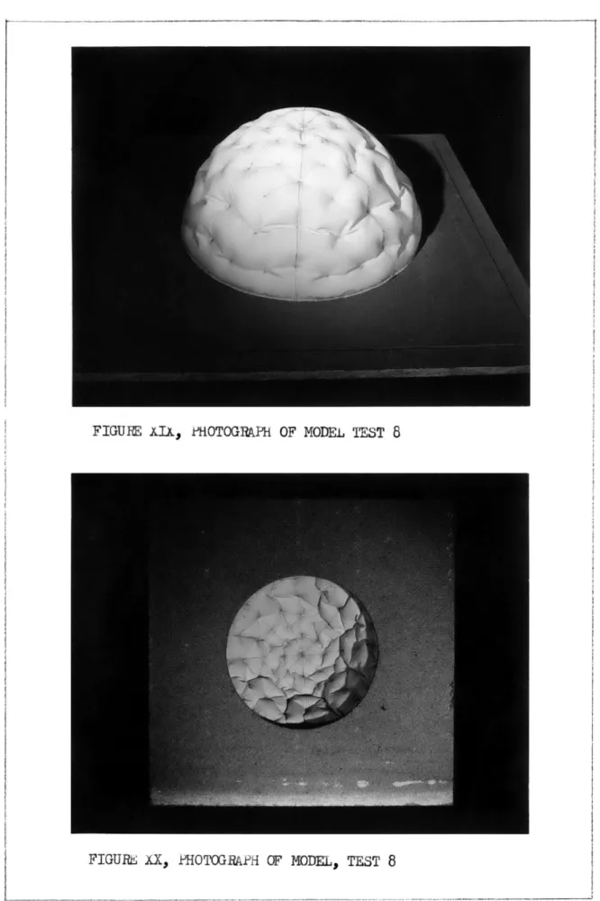
-47-TEST 8 - FIGURE XVIII -4- 12"1 201 PLAN
6"
9' ,# SECTION DESCRIPTION8 equal divisions patterned to form
a hemispheric dome - point connections
between the two membranes
MATERIALS
leibberized fabric
Stitched and glued seams Po.Lyetho.Lene tube spacers Thread connections
"Celotex" rigid base
-48-FIGURE XIx, PHOTOGRAPH OF MODFL TEST
8
TEST
8
1.
Intent of Test
-
To observe in a doubly curved surface the
effect that buckling has on the overall shape.
It was conjectured
that such a structure would not only stand by itself when inflated,
but that local buckling would not be sufficient to cause a collapse
of the structure as long as the depth is properly proportioned to
the span.
2.
Observations
-
Previous to inflation of the structure it was
observed that the dome stood easily by itself and was considerab.ly
rigid.
This rigidity was attributed to the double curvature of the
structure, and to the material which was thought to be oversized
for the modelt s scale.
When air was introduced into the structure the entire
surface and shape of the dome changed.
The extent of this change
was not sufficient to cause a collapse of the structure, but the
reaction was completely normal to the results of previous
experi-ments.
The surface of the dome inflated and became rigid with
distinct bulging between the point connections of the upper and
lower membranes.
Greater buckling was observed on the lower
membrane,this being attributed to the fact that pressure was
working inward on the curvature of the shape and also due to the
pressure differential.
The resultant action on the structure
tas a foreshortening of the membranes. The local bulging and backling of the material and the local tendency for the material to draw together resulted in this decreasing height of curvature.
3. Conclusions - As a. tests to this time have resulted in forms tending to decrease in size, it was felt that the con-struction should be improved to where this action no longer existed. A.L1 surfaces of single and double curvature will maintain their shape when inflated, providing proper depth and curvature requirements are satisfied. The change in curvature through local buck-Ling is considered undesirable, and instead of an action of reducing the structure in size to reach stability, it would be far better that the structure expand to reach its state of equilibrium. The proposal for the next experiment was to use a unit that was known to ex-pand to reach maximu rigidity. A unit that most closely approximated a sphere was the selection which would be used in a geometric division of a surface of double curvature.
SUIOVUf OF TESTS IN WORKING MODEL FORM OF AIR INFLATED SYSTEMS
These tests were initiated in the belief that a working model of an air inflated system would provide a better understanding of how an air inflated system works. Tests l, 2, and 3 provided a graphic example of the forces at work within inflated units that required external restraint for them to
main-tain equilibrium according to a pre-patterned geometry. Test 4 examined a system of single curvature composed of linear elements patterned in an arch form, which described problems involved in
the single curvature, and in the use of rigid members combined with an air inflated structure. Test 5 was the investigation of a surface of double curvature that required special consideration for shear and bending forces in an air inflated system. Test o
dealt with an investigation of the proportions of an air inflated unit, while Test 7 combined these units with greater depth into
a sing.Ly curved arch form. Test b dealt with the problem of buckling through the use of a hemispheric domical form; a probLem
that has been observed in all previous experiments and needed further consideration before a summary of work could be completed.
These experiments greatly aided in the authorst understanding of the prob.Lems and characteristics of air inflated systems. There is a danger in approaching a research project through these means, however; for there can exist a lack of structural scale of
-52-materials and joinery of -52-materials. With a Lack of materials technology there is a possibility of reaching conclusions from observations that are not exact. These experiments are onLy rough approximations, but it was found through observation that the most successtuL inflated unit is one that geometrica.lly approaches a sphere and the most stable structura.L system is a
form of double curvature. From these two conclusions a design
proposal was made for an air inflated structure.
VROFOSAL FOR AN AIR STHJCTURE UTILIZING THE RINCIeLE OF AIR SUFORT THROJGH INFIATED CELLULAR UNITS
A. Selection Of Form
Functional requirements
The general functional use that has been stated has well defined program requirements. A spectator sport activity requires a plan that organizes a stadium type of seating a-round an arena. A square or rectangle in plan lends itself to this type of activity if optimum seating requirements do not include the ends of the arena but only the sides.
The volume of the space is determined by code in regards to volume per person, but in general, space which is graduated from low at the edge to high in the center is
de-sirable.
Structural considerations
The air structure acts structurally as a thin shell,
and according to thin shell theory a curvature is required to eliminate bending and shear stress. Forms of double curvature are especial.ly appropriate, for if the resistance of very thin sheets depends upon its curvature, the double curvature becomes its maximum expression.
r
If by program requirements or preconception the plan of the structure is designated a square or rectangle, then in order for the form to be of double curvature it must be trans-lated or more properly transformed from straight lines.
Adaptations of domes to square pLans in history pro-duced the "squinch" and the more sophisticated pendentive. If
the dome were not required as the surface of double curvature,it would be possible to create a surface of double curvature em-anating from a square plan by simpLy continuing the "squinch" according to a pre-estab.Lished geometry.
One type of surface that is evolved this way is a "pucha". It is a surface of transformation of a plane curve (generatrix) similar to itself when rotating or translating. This is a surface of similar section. The "puuna", specifically, is a cloister vault without edge on a square plan (Figure VIII) where the directrix is a straight line and the generatrix is a variable circumference.
There are a number of surfaces of translation that produce a projection to a square plan but that have not been con-sidered due to mechanical requirements (see section H).
B. Membrane Theory In Relation To Form.
Theoretical analysis for thin shell construction is
-5-well documented2,3 but this is for surfaces of the same curvature. A domical surface as a thin shell can be theoretically determined with accuracy but a surface that is not of the same curvature pro-duces difficulties in analysis.
This is an objection to the design of a structure like a "puchla" because of the apparent complicated ca-lculations that are necessary to derive its relatively simple form. It is con-venient to remember that very few surfaces of double curvature
can be mathematically analysed and that approximate methods are generally used for most practical applications.
Static determinations of a "pucha" in relation to mem-brane theory are possible. In general these would be the same for a spherical surface4, except that static conditions would vary at
2Norris, C.H. (k-rof. of Civil Eng., M.I.T.), "Ana.ysis of She.Lts," Unpublished Notes.
3Timoshenko, S., Theory of k.lates and Shells, New York McGraw-Hi.Ll, 1940.
hKobayashi, A.S. and A.J. Durelli, Feasibility Studies For Air-Cellular Featherweight Housings, Thase Report A&F No. &103, Contract No. AV 30 (002)-1592, Armour Research Foundation
of Illinois Institute of Technology, Chicago Lo, Illinois, March
.1957, Section III.
-50-the edge because of greatly reduced curvature. The greater surface of the "pucha" would act in pure tension or comipression except at the edge and corners where reduced curvature would introduce bending and shear stress.
C. The Air Inflated System And Its Static Analysis. Theory
The static conditions of a atructure will not change whether the system is of concrete or of air inflated cells. Membrane theory of thin sheLLs is held equa.Lly valid for air structures. This premise is true if the individual air in-flated unit is equilibriated and the membrane is pre-tensioned sufficient.Ly so that compressive loads do not exceed the tensile stress that is applied to the membrane by the air pressure.
Geometyof Individual Units
From the previous studies in this report it has been empirically determined that the geometry of the individual unit is of great significance if the total structure is to be statica.LLy in equilibrium. The inflated sphere has been determined as the ideal individual unit shape. lhe geometry of spheres over a sur-face of double curvature is quite complex, though, and further complexity arises if the surface is of a varying curvature.
Problems of joinery are increased and solutions for water integrity
-57-are comp.Licated.
Additional problems of geometry arise due to solutions involving static considerations. In order to solve the problems of bending and shear stress introduced in the "pucha" at the edges and corners, some degree of reinforcement is necessary. It is possible to establish a geometry which introduces smaLLer inflated units at the edge and corners that graduate to larger units over the greater surface. The theory behind this geometry is that a greater number of units at the edge and corners would substantially increase the web action in these areas, counteracting the bending and shear stress. A system of spherical units that satisfies thi0 geometry seems difficult to establish, primarily because points of tangency occur in a complex manner.
The use of a unit that approaches the sphere in a volume and external surface area relationship could better pro-vide a system that satisfies the geometrical requirements in relation to static solutions. A cube or a shape that approaches a cube is a geometric form that would create nearly equal stress patterns over its surfaces when inf.lated. 'Ihe combination of
these units in a reticular system would then provide a more sat-isfactory answer to joinery and water integrity problems.
Static Stability and Erection krincip.Les
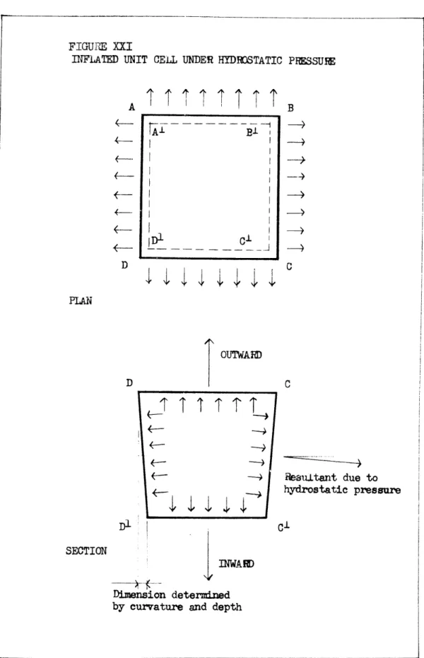
erection principles of an air celliular system. When pressure acts internaliLy on the surface of a celluLar unit, the forces resolve themselves into a state of self-equi-Librium. From geometry it is obvious that the resultant force acting on the surface A3CD is Larger than the resultant f orce acting on AtBtC'D1 (Figure LAI). A net force then acts in the outward
direction. This force is balanced by the forces which are acting on the sides of the unit. If the sides are completely restrained then the inflation of the unit wi.LL f orm a uniform
tension field over the upper and lower surfaces.
The radial distance between the two membranes varies as pressure is introduced into the unit. 'he curvature
intro-duced into the upper and Lower surfaces resolves the restraining
force on the edge into 2 components which establish a uniform tensile membrane force on the unit.
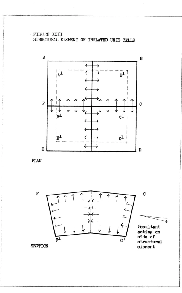
When several of these inflated units are joined to-gether to form a structural element, the resultant forces acting on the sides of two neighboring units wiLl balance each other
(Figure AII).
(This above statement presupposes that the equilibrium condition of a unit is not greatly altered by the joinery. If
it is altered, then under inflation v esultant forces acting on the sides of two neighboring units will not balance each other. The
---FIGURE XXI
INFLATED UNIT CELL UNDER HYDROSTATIC PRESSURE
\
\ d
B C PLAN OUTWARD C Hesu.Ltant due to hydrostatic pressure Cl SECTION IN ]RWAD Dimension determinedby curvature and depth
I
TI
I'
T T
A
D
~~Kb
~- U ~-'---________________ -
-FIGURE XXII
STJCTURAI ELEMNT OF INFLATED UNIT CELLS
A F E -61-B E - 4 PLAN F SECTION B C D C Pesultant acting on side of structural element
balance can only occur in this situation if a copressive stress can be taken along the line of joinery between units, or it wiJ. reso.lve itself in a buckling of material along this Line. This action wiJJL tend to reduce the curvature of any surface if the radia.. distance between two surfaces of a unit is less than the distance across a symmetrical unit. This relates back to the sphere or a volume geometricai.Ly close to a sphere as being the
most ideal unit, where the tensile stress across the surface of
a unit is relatively equal.) Authorst note in parenthesis. Assuming the outside forces on this group of units to be equilibriated, then the differential resultant force of the inside and outside surfaces now tends to push the center of the
group outwards. This force is balanced by the uniform tension field applied by the forces acting on the sides of the unit.
The net effect of alt such forces is similar to an equivalent membrane with a thickness whlich is equal to the sum of the upper
and lower membranes, loaded hydrostatically and under a uniform tension field. The hydrostatic pressure which contributes to a rise in the center of the equivalent unit is equal. to the in-flation pressure in single wal.i. air supported structures.
The above paragraph provides a base for the theory of
-602-cellular air systems and can be expressed for the total system as well as each unit or a group of units.
Size of individuaL units
The size of any individual unit cell is a function of the tensile strength of the membrane material. This can be visualized by the construction of two units of different size using the same fabric surface. The smaller unit obviously is stiffer and will deform less than the larger unit when an ex-ternal force is applied. The specific size would have to be determined in relation to deformations that would not render the air structure unstable.
D. Edge Conditions In Relation To Tension Ring.
Any shell structure, if the curvature is less than a hemisphere, requires an edge member. This is equauly true for an air structure although the size of the edge member would be smaller due to the reduced dead load of an air system. Con-tinuous support in the form of a tension ring would be re-quired to resolve the latitudinal tensile stresses that exist at the edge of the system.
The design of the edge member is primarily a structural consideration, but mast also be thought of in terms of the
-03-structuret s mechanical requirements, and in its relation to the esthetics of a doubly curved she.LL structure' s transition to the ground (see Section H).
E. Forces Due To Wind Load
Additional forces exerted on surTaces of double cur-vature due to wind Loading have been determined theoreticaLy7
and empirically through wind tunnel tests.s In general it may be said that wind loading tends to exert a negative or lift-ing force on a doubly curved surface (air-foil action). In a surface of low silhouette the compressive force that may be ex-erted on one side would be minimized.
The above statements are generally correct, but they oversimplify the action of wind loading and the true stress
distribution would be quite comp4.ex, depending upon wind conditions.
7.
Cit., Timoshenko, p. 374.8a.
Cit., Kobayashi and Durel.Li, p. 2b.9Catalano, E.F., Student Publications of the School of Design. "Two Warped Surfaces", Nortn Carolina State Co.Llege, Raleigh, North Carolina, Vol. 5, No. ., 195.,, p. .L3.
-04-Empirical data gathered in wind tunnel tests on scale models would provide stress distribution patterns of a specific nature.
An effective method of counteracting unequal Loads due to wind on the structure is the provision of an edge member
of sufficient dimension to dissipate and "spoil" the full force of the wind. The edge member serves as a baffle to wind loads which are most effective in producing a negative or air foil action on the structure. The air, instead of striking the sur-face and flowing over the membrane in an even Line, is broken into small turbulences which have less of a tendency to create highly negative force components on the surface of the structure.
F. Joiner Connections Of Individual Units Togethe
In the previous section on the geometry of individual units, it was established that a cube or a form in geometry ap-proximating a cube would give a fairly equal stress pattern over the surface. The selection of a planimetric volume rather than a curved volume facilitates the joinery of units together within a geometric order. Joinery would be accomplished by connecting two units along the upper and lower edges with a zipper. A
zipper that is watertight and would resist the membrane tensile stress is desired. The only additional problem in the connection
F
of units together occurs at the closing of four corners. A
seal would be created here, by the use of a gasket of neoprene or some similar material that would be secured by anchorage at the top and bottom surfaces.G. Mapping Of Surface
The mapping of the surface according to a pre-estab-Lished geometry c ould be accomplished through direct projection. From the geometry established in plan, projection to the curved surface is accomplished by the location of points on that surface in re-lation to their distance from the plan of projection (Figure lXIII).
H. Mechanical Considerations
Recent construction of air inflated structures has generaJ.y accepted a requirement for continuous air supply to maintain structural equilibrium. This is one solution that solves many of the practical problems of maintaining positive control over air pressure within the system. Conditions such as changes in temperature causing expansion or contraction of the air molecules, and the possibijlity of small openings existing in the surfaces of the structure, indicate that a continuous suppJy of air can satisfy practical considerations of the system.
FIGURE XXIII
MAPPING OF A "PUCHA" SURFACE THROUGH LOCATION OF
ANY POINT ON ITS SUIFACE
V
I-P LON A AEH B 'H RESE 2AICH WITH RESE f,
AEH B