Cell mechanics in flow: algorithms and
applications
Doctoral Dissertation submitted to the
Faculty of Informatics of the Università della Svizzera italiana in partial fulfillment of the requirements for the degree of
Doctor of Philosophy
presented by
Kirill Lykov
under the supervision of
Igor V. Pivkin
Dissertation Committee
Rolf Krause Università della Svizzera italiana, Switzerland
Olaf Schenk Università della Svizzera italiana, Switzerland
Petia Vlahovska Northwestern University, USA
Chopard Bastien University of Geneva, Switzerland
George Lykotrafitis University of Connecticut, USA
Dissertation accepted on 7 September 2017
Research Advisor PhD Program Director
Igor V. Pivkin Walter Binder
I certify that except where due acknowledgement has been given, the work presented in this thesis is that of the author alone; the work has not been submit-ted previously, in whole or in part, to qualify for any other academic award; and the content of the thesis is the result of work which has been carried out since the official commencement date of the approved research program.
Kirill Lykov
Lugano, 7 September 2017
Abstract
The computer simulations are pervasively used to improve the knowledge about biophysical phenomena and to quantify effects which are difficult to study ex-perimentally. Generally, the numerical methods and models are desired to be as accurate as possible on the chosen length and time scales, but, at the same time, affordable in terms of computations. Until recently, the cell mechanics and blood flow phenomena on the sub-micron resolution could not be rigorously studied using computer simulations. However, within the last decade, advances in meth-ods and hardware catalyzed the development of models for cells mechanics and blood flow modeling which, previously, were considered to be not feasible.
In this context, a model should accurately describe a phenomenon, be compu-tationally affordable, and be flexible to be applied to study different biophysical changes. This thesis focuses on the development of the new methods, models, and high-performance software implementation that expand the class of prob-lems which can be studied numerically using particle-based methods.
Microvascular networks have complex geometry, often without any symme-try, and to study them we need to tackle computational domains with several inlets and outlets. However, an absence of appropriate boundary conditions for particle-based methods hampers study of the blood flow in these domains. An-other obstacle to model complex blood flow problems is the absence the high-performance software. This problem restricts the applicability of the of particle-based cell flow models to relatively small systems. Although there are several validated red blood cell models, to date, there are no models for suspended eu-karyotic cells .
The present thesis addresses these issues. We introduce new open boundary conditions for particle-based systems and apply them to study blood flow in a part of a microvascular network. We develop a software demonstrating outstanding performance on the largest supercomputers and used it to study blood flow in microfluidic devices. Finally, we present a new eukaryotic cell model which helps in quantifying the effect of sub-cellular components on the cell mechanics during deformations in microfluidic devices.
Acknowledgements
First of all, my utmost gratitude goes to my thesis adviser, Professor Igor V. Pivkin, for his guidance, opportunity to learn and develop myself. I am thankful to him for connecting me with the researchers all over the world, providing access to supercomputer resources and for excellent opportunities to visit scientific con-ferences. Professor Pivkin taught me how to work on scientific problems and deliver the results in journal papers and conferences.
I would like to express my gratitude to all faculty members of the Faculty of Informatics for their advice and the great courses. I also thank the Faculty staff for their tremendous help in any paperwork and activities. My gratitude is extended to the Swiss National Supercomputing Centre staff for providing computational resources and support. I also thank our collaborators, especially, Xuejin Li, Diego Rossinelli, Yu-Hang Tang, Dmitry Alexeev, Yasaman Nematbakhsh, Professor Pet-ros Koumoutsakos, Professor George Em Karniadakis, and Professor Chwee Teck Lim for their knowledge and contribution.
I am grateful to my dissertation committee, Professor Rolf Krause, Professor Olaf Schenk, Professor Petia Vlahovska, Professor Chopard Bastien, and Professor George Lykotrafitis who have been kind to critique my work as readers of this Thesis.
Last but certainly not least, I would like to express my deepest gratitude to my family. My parents, Elena and Alexander, and grandfather, Anatoly, have fostered my developments since childhood by encouraging my interest in Mathematics and Computer Science. I thank my wife Maria for her love and support during the years at Ph.D. program.
My research has been supported by generous grants from Swiss National Sci-ence Foundation (200021_138231, 205321_173020) and Platform for Advanced Scientific Computing (PASC), as well as Swiss National Supercomputer Center (CSCS) grants for supercomputing time (u4, s311, s340, s422, s653, s747).
Contents
Contents vii
List of Figures xi
List of Tables xvii
1 Introduction 1
1.1 Summary of contributions . . . 3
1.2 Outline . . . 4
2 Background and related work 7 2.1 Introduction . . . 7
2.2 Cells composition and mechanics . . . 8
2.3 RBC models . . . 10
2.4 Eukaryotic cell models . . . 13
2.4.1 Suspended cell models . . . 15
2.4.2 Adherent cell models . . . 16
2.5 Cell suspension simulations and boundary conditions . . . 19
2.6 Large scale simulations . . . 20
2.7 Summary . . . 22
3 Numerical methods 23 3.1 Introduction . . . 23
3.2 Dissipative Particle Dynamics method . . . 24
3.3 Multiscale viscoelastic RBC model . . . 25
3.4 Summary . . . 27
4 Open boundary conditions 29 4.1 Introduction . . . 29
4.2 Inflow/outflow boundary conditions . . . 30 vii
viii Contents
4.3 Validation: flow in a pipe . . . 34
4.4 Application: flow in the bifurcations . . . 37
4.5 Application: flow in capillary networks . . . 39
4.6 Summary . . . 39
5 Large scale blood flow simulations in microfluidic devices 41 5.1 Introduction . . . 41 5.2 Target platforms . . . 43 5.3 Software design . . . 45 5.3.1 Memory layout . . . 46 5.3.2 Cluster-level optimizations . . . 47 5.3.3 Node-level optimizations . . . 47 5.3.4 GPU-level optimizations . . . 48 5.4 Microfluidic devices . . . 50 5.5 Large-scale simulations . . . 51 5.5.1 Device I: CTC-iChip . . . 51
5.5.2 Device II: Funnel ratchets . . . 53
5.6 Performance results . . . 53
5.6.1 GPU kernels . . . 56
5.6.2 Time scales separation . . . 58
5.7 Summary . . . 58
6 Eukaryotic cell model 59 6.1 Introduction . . . 59
6.2 Materials and methods . . . 61
6.2.1 Experimental setup and material preparation . . . 61
6.2.2 Cell Model . . . 63
6.3 Results and Discussion . . . 68
6.3.1 Validation of cell model, microfluidic device II . . . 71
6.3.2 Validation of cell model, microfluidic devices I and III . . . 71
6.3.3 Effect of the cytoskeleton . . . 73
6.3.4 Effect of nucleus . . . 75
6.3.5 Effect of the cell viscosity . . . 76
6.4 Summary . . . 76
7 Conclusion 79 7.1 Future directions . . . 80
ix Contents
Appendix A Polarizable coarse-grained protein model for DPD 83
A.1 Introduction . . . 83
A.2 Methods . . . 84
A.2.1 Dissipative Particle Dynamics . . . 84
A.2.2 Particle-Mesh Ewald electrostatics . . . 86
A.2.3 Polarizable water for DPD simulations . . . 88
A.2.4 Polarizable protein model . . . 89
A.2.5 Implementation, Program and System Preparation . . . 93
A.2.6 Estimation of absolute error . . . 93
A.2.7 Simulation details . . . 94
A.3 Results . . . 96
A.3.1 Calibration simulations used to define model parameters . 96 A.3.2 Simulation of backmapped structures in all-atom MD sim-ulations . . . 97
A.3.3 Validation on 5 different proteins . . . 98
A.4 Summary . . . 99
Figures
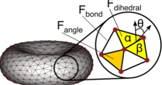
3.1 RBC membrane model made of 500 vertices. Every edge (black) is an elastic spring, every triangle (orange) contributes to the elastic energy as well as to volume/area conservation term, every couple of adjacent trianglesα and β (yellow) contribute to the bending rigidity. . . 26
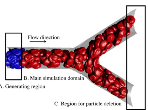
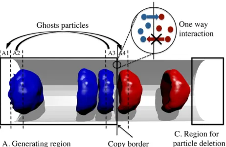
4.1 Simulation of blood flow in a microvascular bifurcation using the proposed open boundary conditions. The simulation domain is subdivided into three regions: generating region with fully de-veloped flow, main simulation domain, and outlet region where particles are deleted. Fluid particles and frozen wall particles are not shown for clarity. . . 31 4.2 Schematic illustration of the computational domain of an open
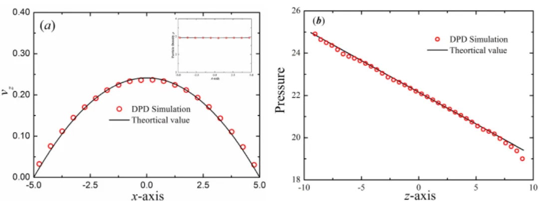
system. The generating region is divided into zones: zones A2 and A3 are sources of ghost particles while zones A1 and A4 are used for placing ghost particles. As soon as a particle crosses the copy border, its copy is created. There is one way interaction be-tween particles in the generating region and particles in the main simulation domain. . . 33 4.3 Verification of the accuracy of the proposed method. (a) Velocity
profiles in the cross-flow (x-axis) direction of the Poiseuille flow corresponding to open boundary conditions. The incompressible Navier-Stokes solution is shown with lines. Inset shows the parti-cle density profile in the cross-flow (x-axis) direction of the Poiseuille flow. (b) Pressure profile for the Poiseuille flow along the z direc-tion. The symbols represent the DPD simulation results and the solid line represents the analytical solution. . . 35
xii Figures
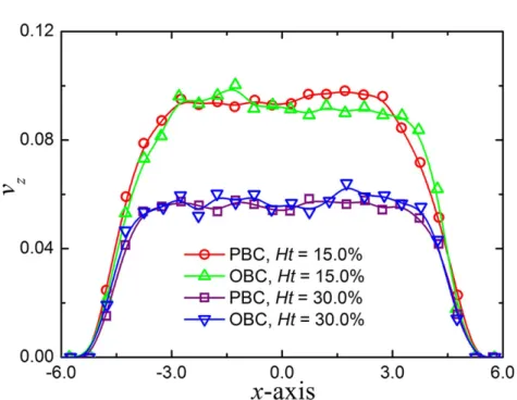
4.4 Validation of the open boundary conditions. Typical velocity pro-files of blood flow in microtubes at Ht = 15.0% and 30.0%. The
simulation results are compared to those in periodic systems at same hematocrit levels. x and z represent the radial and axial distances for the cylinder geometry; vz is the velocity along the flow direction. . . 36 4.5 Particle recovery efficiency with respect to flow rate ratio. (a)
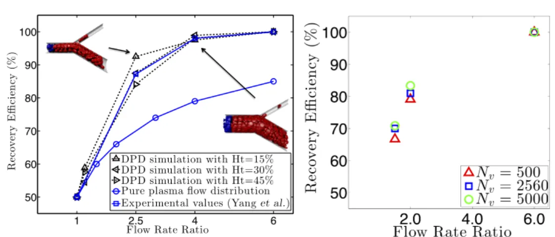
Par-ticle recovery efficiency at different hematocrit levels. Two snap-shots of the RBCs at microvascular bifurcations with flow rate ra-tios of 2.5 and 4.0 at Ht = 45.0% are shown. Simulation data (black squares) from [133] are shown. In the figures, red and blue particles belong to RBCs. Fluid and solid wall particles are not shown for clarity. (b) Particle recovery efficiency at different levels of coarse-graining of the MS-VE-RBC model at Ht = 15.0%. The simulations are conducted using the MS-VE-RBC model with
Nv = 500, 2560 and 5000. . . 37
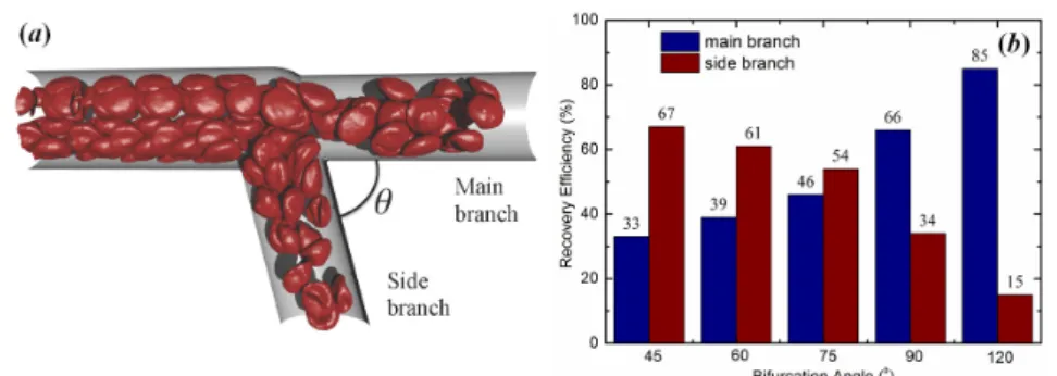
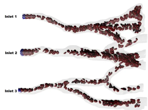
4.6 Effect of bifurcation angle on particle recovery efficiency. (a) A sketch of the microvascular bifurcation model by changing the bi-furcation angleθ. In this model, the diameter of the parent branch is 20.0µm, and the diameters of two daughter branches are both 16.5µm. The average velocity of blood flow in parent branch is about 0.12 mm/s. (b) Relationship between the particle recovery efficiency and bifurcation angle. . . 38 4.7 Snapshot for simulation of the blood flow in part of arterial
net-work with three inlets and multiple outlets. The complex mi-crovascular network was constructed using the angiogenesis model.
. . . 39 5.1 (a) The separation of the temporal scales between solvent and
cells allows us to consider multi-timesteps algorithms[206]. (b) The workload of a cell is mapped to a warp so as to decrease warp divergence and work imbalance. Firstly, the particle count of the surrounding cells is fetched, then the prefix sum is computed. . . 48 5.2 Device I: (a) Stage 1 of the CTC-iChip indicating the initial and
final position of the 1 CTC spiked in 200,000 RBCs. Device II: (b) Funnel ratchets geometry. . . 51 5.3 (a) Simulation of the first module of the CTC-iChip with 200,000
RBCs spiked with 1 CTC. (b) Experiment [103] of RBC flows in the CTC-iChip geometry (left part) and simulation (right part). . . 52
xiii Figures
5.4 Device II, simulation of the funnels ratchet (left), CTCs are squeez-ing through funnel constrictions (right). . . 53
5.5 (a) Device I, displacement in the Y -direction of the CTC versus time. (b) RBCs count between columns of obstacles with Range ID. Initially, all cells placed below column with ID 7, with time some cells distribution becomes smoother. (c) Device II, the evo-lution of the cell distribution. . . 54
5.6 Distribution of the GPU execution time. . . 57
6.1 (a) Microscopy of a cell with nucleus shown in blue. (b) Three component cell model: cell membrane is shown in gray, nucleus is in green, the cytoskeleton is in orange, the connections between cytoskeleton and membranes are in black. Cytoskeleton network model is composed of long and stiff filaments (orange) connected by short cross-links (blue). . . 60
6.2 (a) Micropipette aspiration experiment. (b) Simulation snapshot of a cell during the micropipette aspiration. . . 61
6.3 (a) Comparison between experimental data and simulation for mi-cropipette aspiration, where Ln is normalized indentation length. (b) Cell viscosity as a function of dissipative force parameter γ and cutoff length Rc obtained from micropipette aspiration
simu-lations. . . 62
6.4 Microscopy image of section of the device. . . 63
6.5 (a) Microscopy of a MCF-10A cell squeezing between obstacles. (b-c) Simulation snapshots for a MCF-10A cell model squeezing between two diverging constrictions. Fluid particles are not shown. (d) Comparison between experiments and simulations for cell ve-locities. . . 69
xiv Figures
6.6 (a-c) The simulation results for the effect of the cytoskeleton fil-aments number density Nf il on the elastic modulus (orange) and
velocity (green). (d) Influence of the cross-links NC L to filaments Nf il density ratio on the elastic modulus (orange) and on velocity (green). (e) Influence of the elastic modulus on the velocity for the case when the stiffness is changed by varying filaments density
Nf il (green) and for the case when we varied cross-links density
NC L (orange). (f) The relationship between nuclear-cytoplasmic (NC) ratio and cell elastic modulus, E and velocity. (g) Effect of filaments number density inside the nucleus on cell velocity. (h) The impact of nuclear laminar properties varied using parameter
lma x in the nucleus membrane model on the cell velocity. (i) Effect of viscosity on cell velocity in the microfluidic device. . . 74
A.1 Coarse-grained model of polarizable amino-acids and water. The peptide backbone is represented by 2 hydrophilic I type beads (black) and a dipole (negative charges blue, positive charges -red), while the sidechain is attached perpendicular to the 2 back-bone atoms. The polarity of sidechains is modeled by point charges, while the aliphatic groups are represented by hydrophobic beads (cyan). We use a polarizable water model consisting of one central bead and 2 Drude particles carrying opposite charges. Each of the different aminoacids has been distributed into different classes of aminoacid models with different representations of the sidechain - one bead, aromatic sidechains and hydrophilic sidechains. . . 85
xv Figures
A.2 Experimental structures of TrpCage (a), TrpZip2 (b), GB1 (c) , the WW-domain (d), the Peripheral binding subunit (e), Villin headpiece (f) and the B-domain of Protein A (g) simulated in the present work. TrpCage and TrpZip2 were used for the calibration, so that the coarse-grained model could reliably describe formation ofα-helical and β-stranded peptides. GB1, the WW-domain, the peripheral binding subunit, Villin headpiece and the B-domain of Protein A were used for the validation of our new model. TrpCage (Sequence: NLYIQWLKDGGPSSGRPPPS [160]) PDB : 1L2Y. Tr-pZip2 (Sequence: SWTWENGKWTWKX[26]) PDB : 1LE1. GB1
(Sequence: MTYKLILNGKTLKGETTTEAVDAATAEKVFKQYANDNGVDGEW-TYDAATKTFTVTE) PDB : 2J52,[241]. (d) WW-domain (sequence
: GATAVSEWTEYKTADGKTYYYNNRTLESTWEKPQELK), PDB : 1E0L [142]. (e) Peripheral binding subunit (sequence : VIAMPSVRK-YAREKGVDIRLVQGTGKNGRVLKEDIDAFLAGGA), PDB : 2PDD[101]. (f) Villin headpiece (sequence : MLSDEDFKAVFGMTRSAFANLPLWKQQN-LKKEKGLF), PDB : 1VII[148]. (g) B domain, Protein A (sequence
: TADNKFNKEQQNAFYEILHLPNLNEEQRNGFIQSLKDDPSQSAN-LLAEAKKLNDAQAPKA), PDB : 1BDC[69]. For the NMR struc-tures, we chose Model # 1 as reference structure. . . 86
A.3 (a) Probability plot of coarse-grained simulation of TrpZip2 as function of RM S DCα−Cα to the native structure (given by forward mapped PDB: 1LE1) and the radius of gyration, Rg. (b) Prob-ability plot of coarse grained simulation of TrpCage as function of RM S DCα−Cα to the native structure (given by forward mapped PDB: 1L2Y) and the radius of gyration, Rg. The sidechains have been omitted in this representation and only the backbone atoms are shown for clarity. We do note that the RMSD to the backbone of the native structure is affected by an error of±0.4 nm due to coarse-graining approach as described in the text. The experimen-tal radii of gyration are indicated by a dashed line. (c) RM S DCα−Cα to the native structure as function of simulation time. (d) Color-assigned sequences of TrpCage and TrpZip2. The colors indicate the assignment of each aminoacid to the different groups in the coarse-graining approach (See Figure A.1). . . 88
xvi Figures
A.4 Results from 10 ns all-atom replica exchange MD simulation with backmapped structures obtained from DPD coarse-grained lations as starting structures. (a) Probability plot of all-atom simu-lation of TrpZip2 as function of RM S DCα−Cαto the native structure (given by PDB: 1LE1) and the radius of gyration, Rg. (b) Proba-bility plot of all-simulation of TrpCage as function of RM S DCα−Cα
to the native structure (given by PDB: 1L2Y) and the radius of gy-ration, Rg. (c) RM S DCα−Cα to the native structure as function of simulation time. . . 90 A.5 Results from the folding simulations on GB1, the WW-domain,
Villin-headpiece, the peripheral binding subunit and the B-domain of ProteinA. (a-e) RM S DCα−Cαas function of simulation time. (f-j) Comparison of least square fitted backward-mapped structures from the simulations (cartoon) to the experimental structures (rib-bon) of all 5 proteins. . . 94
Tables
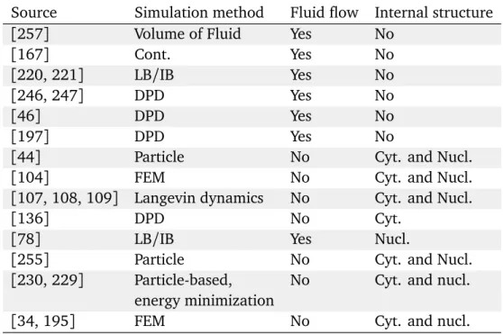
2.1 Computational models and their applications. . . 13 2.2 Computational models classified by methods, fluid flow modeling,
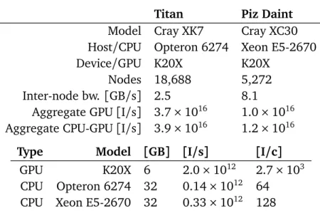
and cell model components. . . 14 5.1 Target platforms. . . 44 5.2 Outperforming factor over LAMMPS. NRis neighbor list rebuilding
frequency. . . 55 5.3 Achieved throughput in terms of instructions and unknowns. . . . 55 5.4 Weak scaling efficiency in percent. . . 55 5.5 Strong scaling efficiency in percent (Piz Daint). . . 56 5.6 Summary of the large-scale simulations on Titan. . . 56 6.1 DPD parameters listed in the format of a/γ. Values shaded with
yellow describe interactions with Rc= 0.5 for repulsive interaction while Rc= 1 for thermostat. For dark gray, Rc= 0.5. . . 65 6.2 List of major parameters with their values. . . 66 A.1 Parameters of the Drude oscillator DPD water model, i.e. angular
constant kθ, equilibrium angleθ0, bond force constant kD, charge of Drude particles |q| and equilibrium bond length d0. Detailed description of the water model can be found in reference[172] . 88 A.2 Conservative force parameter ai j used in the simulations. See
Fig-ure A.1 for the model chosen in the coarse-grained approach. . . . 89 A.3 Equilibrium anglesθ0for the internal coordinates of the sidechains
used in the coarse-grained model. Dihedral angle potentials (type f) with an angle of 180oare applied between the backbone dipole and the sidechain of the nearest neighbor along the polypeptide chain. See Figure A.1 for the model chosen in the coarse-grained approach. . . 90
Chapter 1
Introduction
Blood is a suspension of different cells and a liquid component. The most numer-ous blood cells are red blood cells (RBCs) which occupy up to 45% of the blood volume. By traversing blood circulating system, RBCs deliver oxygen to all the parts of the body. Due to its composition, blood is a multiphase non-Newtonian fluid which leads to many hydrodynamical effects[188, 186]. For example, RBCs tend to migrate towards the middle of the capillary, leaving a cell-free layer next to the vessel walls, which leads to the higher RBCs flow rate in comparison to the solvent. Cell-free layer, mechanics of individual cells and the vessels geometry determine the uneven flux distribution in the bifurcations. Capillary networks are composed of bifurcations, and their transport properties are determined by the blood rheology at bifurcations.
Besides of RBCs, there are many other cells which can be found in the blood: white blood cells, platelets, circulating tumor cells, other epithelial and mes-enchymal cells of different origin. Not all of them positively contribute to the organism health. Probably the most dangerous cells are circulating tumor cells (CTCs) which are the agents of the cancer metastasis. Cancer metastasis is an important problem attributed to nine out of ten cases of cancer deaths. During hematogenous metastasis, CTCs intravasate into the leaky vasculature around the tumor and eventually enter the bloodstream. After circulating for an un-known amount of time, the CTCs extravasate from the vasculature and grow secondary tumors.
Studies of the blood flow effects and cell migration have a great fundamen-tal importance and find many medical applications. The blood flow phenomena on the capillary level impact the oxygen delivery and are exploited in the cell-plasma separation devices [249]. The detection of CTCs in the blood is one of the most potent methods for the early diagnosis of cancer[3] and a key target of
2
liquid biopsies [169]. Improvements in the blood rheology and cell mechanics knowledge led to a wealth of activities in developing microfluidic devices. These devices are used for the suspended cells classification according to the deforma-bility and size, blood-plasma separation, and blood filtering[212, 24].
Although some blood phenomena are quantified, we do not have the full understanding of the blood flow effects, cell migration, and suspended cells me-chanics. The complexity of these problems might be attributed to the interplay between fluid hydrodynamics and cell mechanics. Due to the wide range of cell types with, sometimes, different composition, size, and deformability, cell me-chanics is an especially challenging field. Cells have composite structure and mechanics of the cell as a whole is determined by the interplay of sub-cellular components. Currently, we have a lack of knowledge of the role each component plays during different deformations. This information would help to design the experimental setups for the cell mechanics investigation, which, now, is often long trial and error process.
Due to the complexity of these problems, it is often difficult to quantify in-volved phenomena using experimental studies. Therefore, numerical simulation is a valuable tool accompanying experimental work.
Today, the majority of simulations for microfluidic systems employs contin-uum models to solve the linear viscous Stokes equations of homogeneous fluids in microfluidic. These modeling approaches can handle flow dynamics in com-plex geometries of microfluidic channels, but they cannot resolve the essential biophysics of the flow on the submicron length scale [59]. Another limitation is that continuum models cannot be readily extended to capture cell topological changes, membrane transport, and electrochemical interactions. Such processes are essential for important microfluidic applications ranging from drug delivery and immunoassays [24] to micro-robots for non-invasive surgery [161]. These limitations led, firstly, to the development of the numerous RBC models and, later, the creation of more complicated eukaryotic cell models. The RBC models allowed getting valuable insights into blood rheology in straight pipes and sim-ple microfluidic devices for healthy and malaria-infected RBCs [127, 19, 181]. At the same time, these simulations were, until a very recent time, limited to the simple domain geometries with a number of cells less than 1000. In particular, there were no simulations in the capillary bifurcations with RBCs models able to describe cell deformations accurately. This fact can be partially explained by the lack of the appropriate boundary conditions which would allow performing simulations in the domains which are asymmetric regarding the flow direction. A less visible aspect of the pursuit of RBC flow simulations is that they created formidable high-performance computing (HPC) challenges that limited the
num-3 1.1 Summary of contributions
ber of cells involved in the simulation. Finally, to our knowledge, there are no validated eukaryotic cell models suitable for modeling of the suspended cells un-dergoing significant deformations during passage in capillaries or microfluidic devices.
The purpose of this thesis is to extend the applicability of the particle-based method for the cell flow modeling by providing new models, algorithms, and techniques for their efficient HPC implementation. Open Boundary Conditions would allow performing simulations in the complex geometries, such as capillary networks, and could be applied for quantification of the related flux effects. De-velopment of the computationally efficient software would open the route for the predictive studies in the entire microfluidic devices and could potentially reduce time to solution by two orders of magnitude, thus, making particle-based meth-ods to be more affordable for the blood rheology research. A new eukaryotic cell model would improve understanding of the role different cell components play during cell deformation as well as allow performing predictive studies in the capillary networks and microfluidic devices.
1.1
Summary of contributions
This dissertation builds on Dissipative Particle Dynamics[84] method and Mul-tiscale Visco-Elastic RBC model[180]. Our contributions are as follows:
• Open Boundary Conditions (OBCs) method for particle-based modeling[140]. To our knowledge, our method is the first boundary conditions suitable for the particle-based flow simulations with deformable bodies of arbitrary complexity. This development allowed us to perform, for the first time, sim-ulations in capillary bifurcations and a part of microvasculature network employing an high-resolution RBC model.
• Large-scale simulation of the blood flow [197]. We present algorithms, techniques, and software for simulations of blood and cancer cell separa-tion in complex microfluidic channels with sub-cellular resolusepara-tion. This software was used to perform the largest simulation of deformable cells in complex flow domains to date, involving 1.4B cells and utilizing up to 65.5% of the available 39.4 PetaInstructions/s in the 18, 688 GPU nodes of the Titan supercomputer (Oak Ridge National Laboratory).
• Eukaryotic cell model[141]. We propose a new eukaryotic cell model that explicitly describes sub-cellular components and can describe cell deforma-tions in microfluidic devices. To the best of our knowledge, this is the first
4 1.2 Outline
mesoscale particle-based eukaryotic cell model suitable to study significant deformations which cells undergo in the flow.
• Polarized protein model[173]. We developed a systematic coarse-graining procedure for proteins. We used DPD extended with electrostatic interac-tions. This work is not aligned with the other part of the thesis and, hence, is briefly reviewed in Appendix A.
1.2
Outline
Chapter2 provides background information about relevant cell biology and de-scribes prior modeling efforts. We start with a discussion of the composition of different cells and relevant alternations in the mechanics caused by diseases. Af-ter that, we overview RBC models along with their applications and simulations of blood flow phenomena. Next, we present a review of the recent eukaryotic cell models, emphasizing those which explicitly model sub-cellular components. We, then, discuss the limitations of the existing methods due to the lack of the open boundary conditions. Finally, we review large-scale blood cell simulations, focusing on the computational aspects.
Chapter3 is devoted to the numerical method and RBC model. We provide details of the Dissipative Particle Dynamics method along with fluid-structure interactions implementation and solid walls description. Viscoelastic RBC mem-brane model is discussed in details.
In Chapter 4, we present new OBCs which are robust approach for flow sim-ulations using particle-based methods in complex simulation domains. Specifi-cally, we apply OBCs to study the blood flow. We validate them by finding agree-ment between simulations of RBCs flow in the straight pipe using OBCs and periodic boundary conditions. As a model problem we consider flow simulations in micro-vessels bifurcations. We investigated the effect of the flow rate ratio be-tween branches along with angle bebe-tween them on the cells distribution in two daughter vessels. We, then, apply this method to simulate blood flow in part of a capillary network with several inlets and numerous outlets. This work was done in collaboration with the group of George Em Karniadakis (Brown University).
In Chapter 5, we address numerical challenges in large-scale blood flow sim-ulations in complex geometries. We present software targeting two the most powerful supercomputers in Europe and world correspondingly available at the time. We describe software design and techniques which allowed us to achieve the efficient memory usage. We provide details of the communication strategies
5 1.2 Outline
we employed to achieve the almost perfect weak and strong scalings. We dis-cuss the optimizations and algorithms which allowed utilizing modern GPUs effi-ciently. The developed software was used to perform large-scale flow simulations in microfluidic devices and the obtained results were in general agreement with the experimental data. These simulations involved billions of high-resolution deformable RBCs. This work was one of the finalists of 2015 Gordon Bell Prize and was done in collaboration with groups of Petros Koumoutsakos (ETHZ) and George Em Karniadakis (Brown University).
Chapter6 focuses on the modeling of a single eukaryotic cell. This is a com-bined experimental and simulation study. We describe the experimental setups for individual and collective cells analysis. We introduce a new model for a eu-karyotic cell which explicitly describes sub-cellular components. We perform pa-rameterization and validation of the proposed model. Finally, we present results and discuss the effect of different model components on the mechanics of the whole cell. We did this work in collaboration with the group of Chwee Teck Lim (NUS).
We conclude in Chapter 7 by summarizing the accomplishments in this work and discussing possible future research directions.
Chapter 2
Background and related work
2.1
Introduction
Cells are building blocks of live beings and there is a wide variety of cell types each tailored for a specific purpose in the body. Probably, structurally simplest cells are RBCs. RBCs are designed for oxygen transport and operate as contain-ers of hemoglobin, a long protein which binds oxygen. This function imposes a simplicity of the cell composition: RBCs are made of the membrane and the supporting 2D proteins network. Other cells typically have a more complicated structure incorporating, beside of cell membrane, various organelles, nucleus, and 3D cytoskeletal network. Eukaryotic cells, by definition, are cells that con-tain a membrane-bound nucleus.
Numerous diseases lead to alternations of the mechanics of cells or introduce some atypical cells into the blood stream [162]. Detection and classification of such cells are of the great interest for diseases diagnostics.
Besides of mechanics of individual cells, the rheology of the cells suspension is also of the great importance for many applications. On the length-scale of cap-illaries and small vessels, the multiphase nature of blood along with mechanics of individual cells creates many interesting phenomena.
Techniques, used to study cell mechanics, can be split into two groups. The first group includes methods which operate with individual cells. They are typ-ically used to estimate the viscoelastic properties of a single cell. The second group of experimental techniques, microfluidic devices, have a higher through-put and do not require skilled manual operations. There is a great variety of microfluidic devices and principles they employ to operate. We are primarily in-terested in the devices which exploit hydrodynamics of the cells suspension in the precisely designed flow geometry. The microfluidic devices are also actively
8 2.2 Cells composition and mechanics
used for the blood rheology analysis.
Despite progress in the experimental techniques in cell biophysics, the com-putational modeling is still an indispensable tool. The simulations can help in the acquisition of information of the fluid micro-rheology, including, often unex-pected, fluid flow properties in complex device geometry, and can quantify such complex phenomena as cells adhesion, damage, or signaling [159, 254, 176]. By performing numerical studies, we can improve our understanding of the sub-cellular components mechanics which is valuable for many applications. In par-ticular, quantifying the effect of different cell components would influence the drug discovery by offering a rich drug target space by providing possible cor-rections of cells behavior. Finally, numerical simulations allow prediction of cell behavior in a complex environment and accelerate the design cycle of the mi-crofluidic devices[197].
In this chapter, we give an overview of the state-of-the-art cell models and discuss the corresponding numerical frameworks. The chapter is structured as follows. We start with the discussion of RBCs and eukaryotic cells structure and mechanics, Section 2.2. We, then, provide a retrospective on the RBC model-ing, see Section 2.3. We overview well-established RBC models along with their most prominent applications. Next, we describe the state-of-the-art eukaryotic cell models, Section 2.4. Models for cells in adherent and suspended states are discussed. After that, we overview works dedicated to the cell suspension mod-eling in different microfluidic devices and microvasculature, Section 2.5. The choice of boundaries conditions (BCs) is important for modeling flow in com-plex geometries and BCs are also discussed in this section. In the Section 2.6, we discuss state-of-the-art implementations of cell flow models targeting super-computers.
2.2
Cells composition and mechanics
The RBC membrane comprises a lipid bilayer and an attached cytoskeleton, which consists primarily of spectrin proteins arranged in a network and linked by short actin filaments at junction-complexes. Although this membrane has a mechanism for the fluid and proteins exchange with the surrounding, it is mostly imperme-able to water which leads to volume conservation of a cell. Low compressibility of the lipid bilayer results in area conservation. In contrast to eukaryotic cells, RBC does not have the internal structure.
Eukaryotic cells are composed of a plasma membrane, various organelles, one or several nuclei, and internal cytoskeleton. Mechanics-wise, plasma membrane
9 2.2 Cells composition and mechanics
is similar to RBC membrane: it plays the same role and has similar mechanical properties. Under the membrane, there is a 2D lattice of proteins, called cell cortex, which plays a central role in shape control[203]. Cell cortex is attached to the membrane by membrane-anchoring proteins.
Cytoskeleton of eukaryotic cells is a complex 3D network made of different filaments, and it occupies the space between plasma membrane and nucleus. This component plays a significant role in many cell processes: migration, adhe-sion, diviadhe-sion, stress resistance, and mechanotransduction. There are three types of cytoskeleton filaments: actin filaments, microtubules, and intermediate fila-ments. Actin filaments are semi-flexible biopolymers which exhibit the highest resistance to deformations until some critical stress value. If the stress is greater than this value, they are fluidized. Intermediate filaments can resist moderate deformations, and they do not fluidize under high values of shear stress, hence, providing structural integrity to the cell. Microtubules do not contribute signif-icantly to the cell stiffness. Being interconnected with filaments of other types, they stabilize the cytoskeleton. They also might contribute to the compression resistance under high pressure [21]. The stiffness of the cells is primarily deter-mined by the composition of the internal cytoskeleton[162]. The cytoskeleton is attached to the cell cortex and membrane by numerous linking proteins which also might be specific for a particular cell line [95].
Nucleus is the largest eukaryotic organelle, and it is typically stiffer than the cell itself [75]. Mechanics-wise, the most important components of the nucleus are nucleus envelope and chromatin network. The nucleus envelope is composed of two phospholipid bilayers with an attached lamins meshwork. These bilayers, or membrane, act as a barrier between cytoplasm and nucleus internal struc-ture [121]. In comparison to the cell membrane, it exposes weaker area and volume constraints allowing fluid to get in and out[198]. The nuclear lamina, which is considered to be the main contributor to the nucleus stiffness [63], is 2D meshwork attached to the inner bilayer. According to a very recent study, lamina levels control nuclear strain stiffening at large extensions [214]. Con-trary, chromatin network, which occupies the nucleus volume, governs response to small extensions. Chromatin is also believed to play an important role in the cell migration[63].
Eukaryotic cells of different types might have different mechanical properties. As an example, a cell, which belongs to tumorigenic line MDA-MB-231, is several times softer than non-tumorigenic MCF-10A cell[138]. Besides of cell type, the state of the cell significantly influences the cell mechanics.
Progression of diseases might also lead to alternations in cell components mechanics [162]. Some disorders cause changes in the plasma membrane
elas-10 2.3 RBC models
ticity. For instance, membrane can be softened by HIV [2] or stiffed by specific antigen produced by some parasites harboring cells[154]. Progression of other diseases alters properties of the cytoskeleton. The most prominent example is the cytoskeleton structure degradation and density decrease of epithelial tumor cells [217]. The higher is the metastatic potential of a cell, the lower is the stiffness of the cytoskeleton, and, hence, the cell as a whole [28]. A review of other diseases affecting cytoskeleton might be found elsewhere [191]. Some tissue-specific disorders influence the mechanical properties of the nucleus due to the mutations in genes encoding lamins and associated nuclear envelope pro-teins: Emery-Dreifuss muscular dystrophy, dilated cardiomyopathy, familial par-tial lipodystrophy, as well as over 20 other diseases[198, 199].
2.3
RBC models
The computational models of RBCs help to solve many practical problems. They found applications in testing hypothesis of the cell mechanics, used to predict the performance of microfluidic devices, and improve the knowledge of the cell mechanics changes caused by diseases. RBC modeling is a very active research area, and there are many different modeling approaches, each having its advan-tages. In this work, we are primarily interested in models suitable for the RBC flow modeling. Thus, we do not discuss models which are developed for protein-level resolution modeling [224, 129]. We, instead, focus on the models which, being mechanically accurate on the given scale, are computationally affordable to simulate blood rheology. Here, we briefly discuss corresponding approaches while complete reviews might be found elsewhere[251, 134].
To model suspended cells deformations and rheology in the microvascula-ture and microfluidic devices, a numerical framework should incorporate three essential components: the mechanical model of an individual cell, fluid and fluid-structure interactions models, and solid walls to model microfluidic devices or microvasculature geometry. Every framework utilizes one or several computa-tional methods to discretize the problem. Although the detailed comparison of computational methods is out of the scope of this work, we give a short overview of the most popular methods. The relevant computational methods can be split into three groups: mesh-based, particle-based, and combined. The most popu-lar mesh-based method is Finite Elements Method (FEM). Among particle-based methods, Dissipative Particle Dynamics (DPD) and Smoothed Dissipative Particle Dynamics (SDPD) are used more often than others. Both methods allow
param-11 2.3 RBC models
eterizing the fluid and fluid-structure interactions, while the cell itself is modeled with the help of various many-bodies potentials. Among combined methods, a well-developed and dominating approach is to model the blood plasma with the Lattice-Boltzmann method (LB), RBC membrane forces with FEM, and cell-fluid interactions using immersed boundary method (IB). Further, we will call this numerical framework LB/IB.
Most of these methods can correctly describe hydrodynamics and fluid-structure interactions. A possible disadvantage of DPD, in comparison to other methods, is that DPD parameters do not have a straightforward physical interpretation and have to be tuned manually to achieve necessary properties of the modeled mat-ter, such as viscosity. At the same time, DPD supports thermal fluctuations which, typically, are not supported by other methods. One of the pitfalls of particle-based methods is that they often use the same particles for fluid and membrane which might lead to an unrealistically high mass of the cell membrane. LB/IB method does not have this disadvantage because fluid and cell are modeled by different methods coupled through IB. Yet LB/IB might be more computationally intensive[251].
Simulations, involving mechanical models for RBCs, were established by the pioneering work of Boal et al.[15, 14] that predicted the mechanical properties of the RBC spectrin network. The first 3D spectrin-based RBC membrane model, developed by Discher et al.[32], was used to investigate how the RBC cytoskele-ton deforms during the micropipette aspiration. This work was extended by Li et
al. [131] and the resulting spectrin-level RBC model became a starting point
for later developments. Another extension of Discher’s work was published the same year by Noguchi and Gommper[165]. Contrary to the model by Li et al., Noguchi and Gommper proposed a coarse-grained RBC model and coupled it with Stochastic Rotation Dynamic method, which allowed them to study the ef-fect of fluid flow on RBC membrane. Later, Dupin et al. introduced an alternative low-resolution RBC model using LB/IB formalisms [36]. This model is develop-ing the ideas behind Li’s model yet it is less computationally demanddevelop-ing, and was used to perform one of the first simulation of RBC flow in pipe. A year later, a systematic coarse-graining procedure for Li’s model was introduced[180]. This development provided a systematic procedure for the reduction of the number of vertices by more than one order of magnitude. The DPD method extension, proposed by Pan et al. [168], allowed adding a viscous term to the pure elas-tic RBC model. The resulting model, which will be referred to as the Multiscale Viscoelastic RBC model (MS-VE-RBC), was integrated into a DPD fluid and inten-sively used to study the mechanical properties of individual RBCs[189, 124, 170] as well as blood flows under various conditions[127, 49, 45]. Quinn et al.
per-12 2.3 RBC models
formed combined simulation and experimental study for the RBC passing a mi-crofluidic device [189]. Lei et al. studied blood rheology for healthy and sickle cell anemia RBCs [124]. In a later study, Lei et al. investigated the blood cell flow in pipes with various diameter and hematocrit to study the distribution of cells in the flow, cell-free layer and viscosity of the proposed RBCs suspension.
However, to the moment the most popular approach is to use LB/IB frame-work. Here, we will mention only a few representative works[36, 116, 89, 25]. One of the first large-scale simulations of the deformable RBCs flow was per-formed using LB/IB by Clausen et al. [25]. Using the same method, Krüger in-vestigated tumbling to the tank-treading transition of RBC in the shear flow and simulated deformation of RBC in microfluidic device [116]. In the next study, Krüger et al. investigated the transit of a detailed RBC (1000 vertices/cell) past an array of cylindrical obstacles[117], and studied the RBC deformations close to the obstacle along with the displacement of the RBC due to the characteristic features of the device geometry design. In a later study, this model was used to investigate the displacement of the cells in the deterministic lateral displacement microfluidic devices [233]. Hyakutake et al. studied RBCs distribution in small bifurcations[89].
Besides of DPD and LB/IB, there are many other methods used in the context of RBC modeling. Here we will give a few examples. Finite Volume method for fluid modeling combined with FEM for the cell modeling was applied to study RBCs aggregation[248]. Moving particle semi-implicit method was used to study RBCs flow effects in capillaries, an effect of malaria infection on the RBC me-chanics [90, 4]. Smoothed Particle Hydrodynamics is another method suitable for modeling of the RBC mechanics and flow rheology. Wu and Feng conducted 3D simulations of a healthy and malaria-infected RBC flowing through a sudden constriction, to find out whether the RBC can go through this constriction[243]. There are also various combinations of the before mentioned methods. For in-stance, in the very recent work Ye et al. used SDPD. methods[41], coupled with IB method to describe RBC flow in microvessels[252].
Summarizing, a wide range of different RBC models has been successfully employed for the blood flow rheology studies. MS-VE-RBC model integrated into DPD environment arguably has several advantages over other models. Firstly, MS-VE-RBC model was obtained from a spectrin-level model using a systematic coarse-graining procedure and, hence, can be applied to study problems at an arbitrary level of discretization. Secondly, this model takes into account viscous properties of the membrane, which is hard to achieve using alternative methods. Thirdly, MS-VE-RBC model was extensively validated using optical tweezers and various flow experiments[180, 127, 49, 189]. Finally, the choice of DPD method
13 2.4 Eukaryotic cell models
Table 2.1. Computational models and their applications.
Source Applications Cell type
[257] Squeezing through channels CTC
of different geometry
[167] Flow in pipe H L60,C F 34+
[220, 221] Flow in pipe, cell-wall adhesion WBC
[246, 247] Flow in pipe, CTC, WBC
passage though a narrow slit
[46] Flow in pipe WBC
[197] Flow in microfluidic devices CTC, WBC
[44] AFM SH− SY 5Y
[104] Artificial continuous deformations Osteocyte [107, 108, 109] Cell migration in pipes CHO, HUVEC
and extracellular matrix; filopodia formation
[136] Needle microinjection Zebrafish embryo cell [78] Flow around adherent cell in pipe, hPDC
Micropipette aspiration
[255] Plasma and nucleus membranes Bovine capillary induced by micropipette pulling endothelial cell [230, 229] Stretching, compression, Fibroblast
and shear deformations
[34, 195] Probe indentation Articular cartilage chondrocytes
as a general framework provides a unified way to describe fluid, fluid-structure, and structure-structure interactions.
2.4
Eukaryotic cell models
In comparison to RBCs, eukaryotic cells have a more complex structure, and the modeling efforts in this direction were started later. The advances in computa-tional methods, RBC modeling and significant progress in hardware made this area to be very active in recent years. In this section, we will focus on the models for adherent and suspended eukaryotic cells. We do not consider cell models for the tissue modeling, a review of these models can be found elsewhere[57].
14 2.4 Eukaryotic cell models
Table 2.2. Computational models classified by methods, fluid flow modeling, and cell model components.
Source Simulation method Fluid flow Internal structure
[257] Volume of Fluid Yes No
[167] Cont. Yes No
[220, 221] LB/IB Yes No
[246, 247] DPD Yes No
[46] DPD Yes No
[197] DPD Yes No
[44] Particle No Cyt. and Nucl.
[104] FEM No Cyt. and Nucl.
[107, 108, 109] Langevin dynamics No Cyt. and Nucl.
[136] DPD No Cyt.
[78] LB/IB Yes Nucl.
[255] Particle No Cyt. and Nucl.
[230, 229] Particle-based, No Cyt. and nucl. energy minimization
[34, 195] FEM No Cyt. and nucl.
similar, the modeling efforts for eukaryotic cells started with the application of RBC models with altered parameters. Such models usually represent a cell as an empty deformable shell. Despite oversimplified structure, these models capture the size and the shape of a cell and, being coupled with the fluid model, are often used to predict microfluidic effects such as deterministic lateral displacement or cell margination.
The interest in studying processes which involve significant deformation of the cell and, thus, requiring mechanical response of the internal cell compo-nents, led to the development of approaches which explicitly model nucleus and cytoskeleton. Typically, these models use the same hollow sphere model for the cell membrane and the nucleus. These models were applied to the numerical in-vestigation of such processes as needle microinjection, Atomic Force Microscopy (AFM), cell migration, and deformation in microfluidic devices, see Table 2.1. The classification of the models according to the presence of the sub-cellular components is shown in Table 2.2. We additionally classify models by the sup-port of hydrodynamics and observe that models, which describe fluid, usually do not consider internal cell structure. Computational methods used for the eu-karyotic cells modeling are the same as those utilized for the RBC modeling, see Table 2.2.
15 2.4 Eukaryotic cell models
The variety in cells modeling approaches can be explained by the complex nature of the problem. The first source of this complexity is the diversity in the cell lines along with processes in which they are involved. The second one is the lack of understanding of the role each cell component plays during mechanical deformations. These factors also explain the fact that the current state-of-the-art models are phenomenological and each one is tailored to a very particular cell line and related processes.
For the next two sections, we split the existing models by the application area. The first group contains models for the suspended cells which are usually employed to study fluid flow problems. The second group is dedicated to the modeling of the cells in the adherent state. Some models target problems which are at the intersection of these two groups.
2.4.1
Suspended cell models
The majority of suspended cells are blood cells such as RBCs, WBCs, and platelets. Among these cells, only WBCs are eukaryotic. CTCs, contrary to other cells, are atypical and their presence in the blood indicates cancer metastasis. These cells are used as biomarkers and have attracted a lot of attention in the last decade. Both WBCs and CTCs are several times bigger and stiffer than RBCs. This differ-ence in size between RBCs and suspended eukaryotic cells leads to a rheological phenomenon called margination, which is a process whereby stiff cells are dis-placed to the vessel wall[65]. Margination and related effects are often studied with numerical models. Another popular application of the cell models is to in-vestigate the cell passage in the microfluidic devices. In the rest of the section, we will briefly discuss some recent modeling efforts.
In a series of papers, Takeishi et al. modeled margination of WBCs and CTCs and, in the later work, adhesion of CTCs to vessel walls[219, 220]. This devel-opment allowed them to numerically investigate the effect of the cell size on the flow mode and the cell velocity and identify similarities and differences between leukocytes and CTCs. Further, it was found that the bullet motion enables firm adhesion of a cell to the capillary wall [221]. These results suggest that even under the interaction between proteins responsible for WBC rolling, a cell can show firm adhesion in a small capillary. Modeling-wise, Takeishi et al. employed LB/IB method and empty shell cell representation. For the model validation, sim-ulation results for the deformation of a spherical cell in shear flow are compared with previously published works.
Fedosov et al. also studied WBCs margination but they, additionally, took into account effect of RBCs [46]. It was found that WBC margination occurs
16 2.4 Eukaryotic cell models
mainly within a region of intermediate hematocrits and for relatively low flow rates. Moreover, simulations showed that RBC aggregation slightly enhances WBC margination, particularly at the high hematocrit values. DPD method was used to describe fluid and cell particles.
The work by Xiao et al. is dedicated to the mutual effect of rolling CTC in the capillary on the blood flow dynamics[247]. By the help of computational mod-eling of suspended CTC and RBCs, it was demonstrated that, in the microvessel of 15µm diameter, the CTC has an increased probability of adhesion due to a growing wall-directed force. However, with the increase in microvessel size, an enhanced lift force at higher hematocrit detaches the adherent CTC quickly. An increased blood flow resistance in the presence of CTC was also found. More-over, the significant deformation induced by high flow rate and the presence of aggregation promote the adhesion of CTC. In another work, the same group of authors applied a very similar cell model to investigate an individual cell passing through a narrow slit[246]. Specifically, they studied the effect of cell size, nu-cleus and cell membrane shape on the transmigration through a slit. This model represents cell and nucleus as an empty shell.
Although considered models use different discretization methods, all of them employ a simple empty shell cell representation. This approach can be applied to study phenomena in tubes and microfluidic devices which are caused primarily by hydrodynamical forces. However, such models often lack details to describe processes which involve significant cell deformation such as squeezing in small clefts. In addition, they do not allow quantification of the impact of different sub-cellular components on the studied phenomena.
2.4.2
Adherent cell models
Most of cell lines considered for modeling in this section have a structural func-tion in the body and, hence, they are relatively stiff. Among the numerical model applications, popular experiments are mechanical tests (stretching, com-pression), migration on the extracellular matrix, and microinjection.
Kardas et al. proposed a computational approach to model the structure of bone cells [104]. It was shown that the load acting on the nucleus is rising with increasing deformation applied to the integrins. The numerical simulations demonstrated that the nucleus is more affected by stress if the distribution of intermediate filaments and microtubules are random than if they are regular. The model takes into account integrins, nucleus, centrosome, and cytoskeletal proteins. Computational-wise, FEM was employed to discretize governing equa-tions.
17 2.4 Eukaryotic cell models
Ujihara et al. presented a cell model to study tensile and compression tests[229, 230].During the tensile test, it was observed that the total elastic energy of the model is dominated by actin fibers. The compression test revealed that the align-ment of bundles of actin filaalign-ments significantly affects the cell stiffness. In ad-dition, the passive reorientation of actin filaments bundles perpendicular to the compression induced an increase in the resistance to the vertical elongation of a cell and, thereby, increased the cell stiffness. The model incorporates a cell mem-brane, a nuclear envelope, and actin filaments. This is a particle-based model which utilizes minimum energy concept. The model was validated by compar-ing load-deformation curve obtained from simulation with experimental data.
Dowling et al. presented a study of the role of the active remodeling and contractility of the actin cytoskeleton in the response of chondrocytes (cartilage cells) to shear [34]. The key feature of the model is that it incorporates both passive viscoelastic component and active, describing cytoskeleton remodeling. By the help of numerical simulations, the authors showed that a purely passive cell model is incapable of predicting the response of normal chondrocytes to the stress while adding the cytoskeleton remodeling to the model gives results close to the in vitro study. Interestingly, the passive model can predict drug-treated cells with the disrupted cytoskeleton, which might be considered as evidence that actin cytoskeletal network is the main contributor to the stress resistance during discussed processes. In another paper, where a similar model was used, authors predicted the increased compressive resistance of spread cells compared with round cells[195]. The nucleus and membrane are represented as a passive hyperelastic material, while ODE describes the cytoskeleton remodeling. The equations are discretized by the help of FEM.
Fang and Lai studied the changes in the cell mechanics as a cell shifts from suspended to the adherent state [44]. In order to estimate the cell model elas-tic modulus, simulation of AFM experiment was employed.The force-indentation relationship was used to determine the mechanical changes in cells during state shift. The explicit modeling of the sub-cellular components allowed investigat-ing the impact of different cell components on the resistance to the external stress as well as examine the effect of nucleus presence on the AFM results. The model consists of a cell membrane, nucleus envelope and three internal networks representing microtubules, F-actin, and intermediate filaments. In addition, it takes into account movement of adhesion molecules which allows simulating cell spreading. The model was validated by comparing the AFM simulation results with the experimental data.
Kim et al. developed a model to predict cell migration behavior on 2D and 3D curved surfaces[107]. The simulations revealed that the cell migration speed
18 2.4 Eukaryotic cell models
depends on the cross sectional area of the lumen. The relationship between mi-gration speed and the lumen width agrees with the microfluidic experimental data. This model was also applied to study cell migration on 2D micropatterned geometries[108]. The model is assumed to be used for predictive studies to as-sist in the design of upcoming microfluidic cell migration assays. It takes into account focal adhesion dynamics, actin motor activity as well as cytoskeleton remodeling and nucleus. The further development of the model allowed predic-tion of cell invasion into 3D extracellular matrix (ECM) in response to different extracellular biochemical cues[109]. The new model takes into account filopo-dia penetration dynamics. The average filopofilopo-dia speed was predicted, and that of the cell membrane advance agreed with experiments of 3D HUVEC migration for diverse ECMs with different pore sizes and stiffness.
By the help of numerical modeling, Liu et al. predicted the cell damage in-duced by the needle during the microinjection procedure [136]. In particular, authors quantified the effect of the size, shape of the microinjector tip, and the injection velocity on the cell damage. The proposed model is based on DPD method. It explicitly describes cell membrane as well as the cytoskeleton and motors activity. To validate the model, authors measured the mechanical prop-erties of the model using the particle tracking microrheology. The cell model exposes power law behavior in terms of mean square displacement and lag time. The mechanical moduli obtained from the simulations are in agreement with the experimental data.
Zeng et al. applied cell model to study the role of the actin cytoskeleton network in mechanotransduction and nucleus deformation [255]. During the experiment, modeled in this work, a micropipette is pushed into the cytoplasm of an endothelial cell and then pulled away at a constant rate. By the help of numerical simulations, it was shown that the stress propagation through the ran-dom cytoskeletal network could be a mechanism to effect nucleus deformation, without invoking any biochemical signaling activity. It was reported that nucleus strain varies in a sigmoidal manner with actin filament concentration, while there exists an optimal concentration of actin-binding proteins that maximize nucleus displacement. In addition, a theoretical analysis for these nonlinearities in terms of the connectivity of the random cytoskeletal network was provided. This is a particle-based model which explicitly describes cell membrane, nucleus enve-lope, and cytoskeletal actin network. The simulation results were validated using the experimental data.
The most important common feature of the models discussed in this section is that they take into account, besides of nucleus envelope and cell membrane, mechanics of the cytoskeleton. Hence, these models can describe changes in the
19 2.5 Cell suspension simulations and boundary conditions
cell during different mechanical tests as well as cytoskeleton-related processes. In addition, they give an insight into the impact of sub-cellular components dur-ing particular experiments. What is beyond the scope of these modeldur-ing efforts is the deformation due to the flow and solid-cell interactions which might be useful for investigation of cell behavior in the flow.
2.5
Cell suspension simulations and boundary
condi-tions
With the development of the computational methods and hardware, it became af-fordable to use high-resolution deformable RBC models to simulate phenomena involving numerous RBCs. This, indeed, allowed to study different blood flow effects and perform predictive simulations for microfluidic devices. There are many numerical simulations of RBC flow [165, 149, 150, 189, 52, 135, 49]. By modeling flow in relatively simple domain geometries such as a straight pipe or a periodical cube, these works created a solid background to move towards simula-tions in more complicated domains and, in the past 5 years, numerical modeling of blood flow in complex domains has attracted increasing attention [59, 134, 9, 117]. The limiting factor of particle-based methods is that there is no bound-ary conditions suitable for flow simulation in complex computational domains with multiple inlets and outlets. Periodic Boundary Conditions (PBCs) are the traditional choice, yet it might be difficult or inefficient to apply PBCs to study systems which do not have a symmetry with respect to the flow direction. Due to this methodological gap, all the mentioned flow simulations were performed in systems with PBCs along the flow direction, including some studies of simulating non-periodic blood flow phenomena [18, 96]. To study such effects as plasma skimming in capillary bifurcations, where the blood flow properties such as ve-locity and pressure fields differ drastically at the inlet and outlet regions, there is a need in developing alternative boundary conditions. This is a non-trivial problem, especially for particle-based Lagrangian methods.
For an open boundary system, the velocity profile at the inlet is generally spec-ified, whereas the outflow profiles are rarely known. For a single-phase system, the inflow condition could be simply obtained by extending the inflow length so that the flow becomes fully developed at the inlet. However, for multiphase systems, the inflow conditions even for a fully developed flow are unknown - a situation similar to turbulent inflow in the single phase. For example, for a blood flow, the flow and viscous properties, as well as the cell-free layer distribution in
20 2.6 Large scale simulations
arterioles, differ considerably with the change in hematocrit level and shear rate. Thus, the inflow length should be long enough to generate inflow condition for blood flow. As a consequence, it is inefficient to perform blood flow simulations using this relatively straightforward method because of prohibitively expensive computations.
To the date, there are a few studies that focused on the development of Open Boundary Conditions. An attempt to develop such boundary conditions has been presented by Flekkøy et al.[56], in which the simulation domain includes an aux-iliary buffer domain for particle generation. However, the complexity of the flux control makes it difficult to perform flow simulations. Recently, a new method for such open systems has been developed by Lei et al.[125], where particles at the inlet are generated according to the local flux, and adaptive forces are introduced to control the flow rate at the outlet. This method has been successfully applied to single phase flow in straight channels and bifurcations [125]. However, in multiphase systems, e.g., flows with colloids, polymer chains or RBCs, it is hard to insert them at the inlet and remove them from the outlet. Thus, these two methods cannot be readily extended to the cases of complex multiphase flows.
2.6
Large scale simulations
Most of considered in this chapter cell models are computationally expensive, and simulations of the cell suspension behavior require usage of supercomputers. A prominent example is modeling of the microfluidic devices designed to catch CTCs in the blood flow. CTCs are extremely rare in the blood: there is one such cell per 109or RBCs. To simulate such amount of blood, we need to use over 1012 particles: RBC model requires at least 500 elements to represent the dynamics of a RBC[180] and a huge amount of particles are needed to represent the fluid. The efficiency of the model implementation is an important factor which can limit the applicability of the model. Software, which efficiently uses supercom-puters, can, from one hand, reduce the time to solution and, hence, allows solv-ing problems faster. From the other hand, such software allows modelsolv-ing large scale effects which are difficult to study on a smaller scale. Another important as-pect is that we need to utilize the limited and expensive computational resources efficiently. This section is dedicated to the high-performance implementations of the cell flow models. The efficient implementation of the underlying computa-tional method is also considered here. Most of the work is dedicated to the RBCs modeling since eukaryotic cell models were not yet used in this context.
per-21 2.6 Large scale simulations
formed by Rahimian et al.[190]. They used a boundary integral solution of the continuum linear Stokes equation to simulate 262 Million RBCs, each discretized with 84 vertices, totaling 88 billion unknowns. In terms of throughput, they measured about 290 Million unknowns/s, leading to a theoretical throughput of about 2.6 Billion RBC unknowns/s on Jaguar, Cray XT5. Lattice Boltzmann sim-ulations of the blood flow into a coronary arteries network employed 450 Million non-deformable RBCs observed a throughput of 540 Million unknowns/s and 1 PFLOP/s in double precision on Tsubame [9]. Xu et al. performed blood flow simulations with 50,000 RBCs at the exceptional resolution of 3,300 vertices per RBC using TSUBAME2 supercomputer [248]. Large-scale rheological sim-ulations, albeit with non-deforming RBCs, have reached 4 Millions RBCs [97] on BG/P (maximum 65,636 PowerPC nodes). Another remarkable work in this context was accomplished by LB/IB method [25], performing simulations with 220,000 RBCs and achieving a throughput of 7 Million unknowns/s.
The DPD simulations of RBCs transiting in small microfluidics channels started with modeling the flow in simple computational domains such as straight pipes[189, 48]. These simulations involved maximum 200 RBCs and provided insight on the magnitude of the adhesive forces acting between cells. In the last few years, the usage of DPD has burgeoned for the study of cellular systems and in particular for the study blood flow in microfluidic devices. These results include the first ever combination of experiments and DPD simulations in the study of large de-formations of RBCs in microfluidic devices [189] and the identification of the governing mechanisms for increased blood viscosity in sickle cell anemia [126]. DPD is a very computationally intensive method and it is essential to imple-ment it efficiently. Thus, we review here two state-of-the-art impleimple-mentations of DPD. Currently, software for DPD deployed on supercomputers is based on extensions of code originally developed for MD, such as LAMMPS [183] and HOOMD-Blue [5]. LAMMPS is one of the six projects selected for the Center for Accelerated Application Readiness by the Oak Ridge Leadership Computing Facility (OLCF) and has been extended to perform DPD simulations [164]. The largest LAMMPS/DPD simulation reported 256K particles per node. They sim-ulated 256 Million particles on 1024 Titan nodes with a throughput of 5 - 7.6 Million Particles per second [MP/s][164]. The largest and fastest DPD simula-tions so far had been performed with USER-MESO, LAMMPS fork by Tang and Karniadakis[223]. These simulations employed 1 Billion particles on 1024 Titan nodes with reported throughput of 10− 30 [MP/s] per node, for the simulation of spontaneous vesicle formation. Another package supporting DPD is HOOMD-Blue [5] which aims at taking advantage of the compute capabilities offered by Single Instruction Multiple Thread (SIMT) architectures [64] and has also