HAL Id: hal-00707009
https://hal.archives-ouvertes.fr/hal-00707009
Submitted on 14 Jun 2012
HAL is a multi-disciplinary open access
archive for the deposit and dissemination of sci-entific research documents, whether they are pub-lished or not. The documents may come from teaching and research institutions in France or abroad, or from public or private research centers.
L’archive ouverte pluridisciplinaire HAL, est destinée au dépôt et à la diffusion de documents scientifiques de niveau recherche, publiés ou non, émanant des établissements d’enseignement et de recherche français ou étrangers, des laboratoires publics ou privés.
A User Centric View of Lyee Requirements
Colette Rolland
To cite this version:
Colette Rolland. A User Centric View of Lyee Requirements. International Workshop on Lyee Methodology, 2002, France. pp.1. �hal-00707009�
A User Centric View of Lyee Requirements
Colette ROLLAND
Université Paris1 Panthéon Sorbonne CRI, 90 Rue de Tolbiac
75013 Paris, France
Tel. 33 1 44 07 86 34 – 33 1 44 07 86 45 Fax. 33 1 44 07 89 54
Abstract. The paper deals with the modelling of Lyee user requirements and guidelines to support their capture. The Sorbonne contribution to the Lyee collaborative project aims to reduce the software development cycle to two explicit steps, requirements engineering and code generation by coupling the code generation features of LyeeALL with an interface to capture user requirements. The paper presents a 2-layer meta-model relating the set of concepts to capture user requirements to the set of concepts for the formulation of software requirements that are the input of the LyeeALL generation mechanism. It exemplifies the concepts with example and introduces the guidance support for capturing these user centric requirements.
1. Introduction
The research of the Sorbonne group within the Lyee1 collaborative project is aimed at
developing a methodology that supports software development in two steps, requirements engineering and code generation. The former is the contribution of the Sorbonne group whereas the latter is provided by LyeeALL.
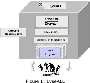
LyeeALL is a commercial Japanese CASE environment which aims at transforming software requirements into code. As shown in Figure 1, the underlying Lyee approach [16] [17] comprises an original framework to structure programs, an engine to control their execution and a generation mechanism to generate programs from given requirements. These requirements are expressed in rather low-level terms such as screen layouts and database accesses. Moreover they are influenced by the LyeeALL internals such as the Lyee identification policy of program variables, the generated program structure and the Lyee program execution control mechanism. As a consequence it is difficult to get the Lyee customer away from the burden of Lyee internals instead of focusing his/her attention on the requirements. Projects conducted in industry with LyeeAll show the need to separate clearly software requirements from user-centric requirements in order to acquire the former from the latter.
1
Lyee, which stands for GovernmentaL MethodologY for SoftwarE ProvidencE, is a methodology for software development used for the implementation of business software applications. Lyee was invented by Fumio Negoro.
Figure 1 : LyeeALL
The Sorbonne group develops research towards meeting this need. As a first step, the group is aiming at:
- (1) defining a user-centric requirements model
- (2) developing methodological rules to support the capture of these requirements in a systematic way,.
- (3) developing a software assistant to guide the capture of user centric requirements
- (4) generating the Lyee software requirements from these user requirements In a second step, the objective is to provide an intelligent software support for the elicitation of high level requirements and the automated generation of the Lyee software requirements.
In this paper we concentrate on points (1) and (2) above. In the next section we introduce the meta-modelling approach which was used to define the user-centric requirements model and we provide an overview of the model. Section 3 contains a description of the model concepts and illustrates them with examples. The next section deals with the process support to help in the capture of user-centric requirements. Some idea of future work is given in the conclusion.
2. Meta-Modelling Approach and Lyee Requirements Meta-Model
At the start of the project, it was quickly realised that Lyee was understood in operational terms such as Process Route Diagram (PRD), Pallets, Signification Vectors, Routing Vectors and the like and it was difficult to get a global, systemic view of it. The need for the latter was felt particularly strongly because :
(a) user-centric requirements are to be related to Lyee software requirements. and a systemic model would help in clearly expressing this relationship.
(b) additionally, the transition form user requirements to Lyee programs called for traversal across different levels of abstraction, a task that the area of modelling and meta-modelling is known to perform effectively.
Meta-modelling is known as a technique to capture knowledge about methods. It has been used for understanding, comparing and evaluating methods [7]. Meta-models were also used as a basis for method-engineering [4] and Case shell construction [3] [9] [13]. A number of meta modelling languages have been proposed to deal with (a) the representation of the product aspects of methods [1] [3] [8] [10] [15] [24] and (b) for modelling the process aspects of methods [12] [20] [21] [23].
We used a meta modelling approach to first model the set of concepts underlying the Lyee software requirements and secondly, to abstract from them the user-centric
requirements model. The result of this effort is a 2-layer meta model2 expressed with UML
notations. The upper layer corresponds to the user-centric requirements model whereas the lower layer identifies the set of concepts required to express software requirements in Lyee terms.
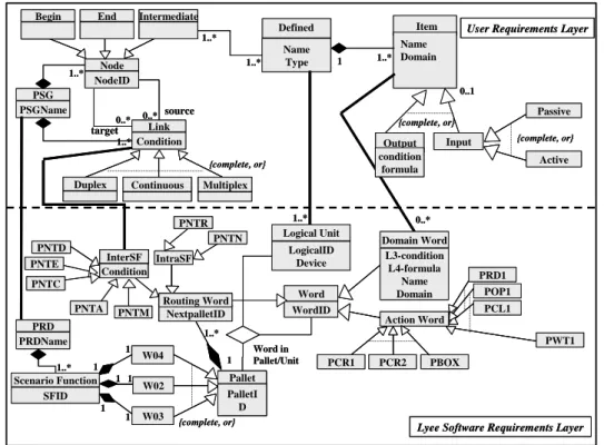
Figure 2 shows the meta-model and highlights the separation between user requirements concepts and Lyee software requirements concepts. The former constitute the user requirement layer whereas the latter form the Lyee software requirements layer.
User Requirements Layer
Lyee Software Requirements Layer
1 1..* Name Domain {complete, or} Input Output source target Link Condition
Duplex Continuous Multiplex
Name Type {complete, or} Node NodeID PSG PSGName 0..* 0..* Intermediate End Begin 1..* 1..* 1..* 1..* 1..* 0..* 0..1 {complete, or} Action Word W04 W02 W03 PNTR PNTD PNTE LogicalID Device Logical Unit SFID 1 1 1 1 1 1 1 1..* NextpalletID
Routing Word Word
WordID Domain Word L3-condition L4-formula Name Domain PRD1 POP1 PCL1 PCR1 PCR2 PBOX PWT1 Word in Pallet/Unit 1..* PNTA PNTM IntraSF PNTN PNTC PRD PRDName Pallet PalletI D Passive Active {complete, or} Item Defined condition formula Scenario Function InterSF Condition
User Requirements Layer
Lyee Software Requirements Layer
1 1..* Name Domain {complete, or} Input Output source target Link Condition Duplex
Duplex ContinuousContinuous MultiplexMultiplex
Name Type {complete, or} Node NodeID PSG PSGName 0..* 0..* Intermediate Intermediate End Begin 1..* 1..* 1..* 1..* 1..* 0..* 0..1 {complete, or} Action Word W04 W02 W03 PNTR PNTD PNTE LogicalID Device Logical Unit SFID 1 1 1 1 1 1 1 1..* NextpalletID Routing Word NextpalletID
Routing Word Word
WordID Domain Word L3-condition L4-formula Name Domain PRD1 POP1 PCL1 PCR1 PCR2 PBOX PWT1 Word in Pallet/Unit 1..* PNTA PNTM IntraSF PNTN PNTC PRD PRDName Pallet PalletI D Pallet PalletI D Passive Active {complete, or} Item Defined condition formula Scenario Function InterSF Condition InterSF Condition
Figure 2 : Lyee meta-model
Let us introduce first, the lower layer concepts to express Lyee software requirements. The essence of the Lyee approach is to reduce software requirements to the description of program variables called words, and to generate the control structure that logically processes these variables and produces the expected result. Despite the traditional design approaches in which both the variables and the control structure of the program must be designed, LyeeALL generates the latter provided an appropriate description of the former is given.
From the design view point, the approach can be compared to declarative approaches for information system design. In these approaches, system design is reduced to a set of predicates from which the state of the system can be derived at any point of time t. Lyee relies on the notion of word and makes the distinction between input words ( these are given value through system communication with the external world) and output words produced by the system. Instead of predicates, Lyee uses formulae to express how to produce an output word. The ordering of word production does not need to be given. In this sense the Lyee approach is declarative.
From the generation view point, LyeeALL is similar to a forward inference engine of an expert system which generates new facts by applying to the existing base of facts at time t those rules having their premises true. Similarly, the Lyee engine saturates the
application of formulae till all the output words are determined. However, as the Lyee engine controls the execution of formulae which are procedural rules and not inference rules, the engine activates a proprietary function to a Lyee specific program structure, the Process Route Diagram (PRD). This structure is hierarchical : a PRD is composed of Scenario Functions (SF), composed of Pallets which are made of Vectors. In order to carry out the generated program control the function generates its own words, such as the action words related to vectors and routing words to distribute the control over the various SFs of a PRD.
The concept of Word is therefore central to the expression of Lyee software requirement, whereas the ones of PRD, SF, Pallet and Vector required by the word processing mechanism of LyeeALL are also part of the Lyee software requirements model. These concepts can be seen in Figure 2 as part of the lower layer of the meta-model.
The upper layer of Figure 2 is centred on three concepts only : Defined, Item and
PSG. This reflects the fact that the user-centric model abstracts from the details of Lyee
software requirements to identify the minimum set of concepts to capture the domain dependent requirements. However the simplicity of the upper layer results fundamentally from the declarative approach of Lyee.
We present the upper layer concepts in the next section and illustrate them with the
Split example. Split a Goal is a functionality which, given a goal statement such as
‘Withdraw cash from an ATM’, automatically decomposes it into a verb and its parameters. For example, Withdraw is the verb, Cash is the target parameter of the verb and from an
ATM is the means parameter. The full functionality identifies 7 different parameters .
However, in this paper we will consider only the two parameters exemplified above, target and means. Besides, the case considered in the following extends when necessary, the Split functionality in three different ways :
(a) the storage of the goal and its decomposition in a database. (b) the retrieval of the goal name from a Goal table in a database. (c) the possible failure of the goal decomposition function.
3. The User Centric Requirements Meta-Model
Interaction driven user requirement capture
In order to comply with the Lyee approach, the user requirements model should be centred on a notion which abstracts from the Lyee internal concept of word. Obviously words required by the Lyee processing mechanism are not relevant at this level. On the contrary, the concern is only with domain dependent words. Besides, there is a need to provide the requirement holder with a means to grasp a ‘set of ‘words’ conceptually associated with one another. We propose the notion of ‘system interaction’ for that purpose. We believe that the Lyee approach, which is output driven, fits with a use case [6] kind of user requirements capture.
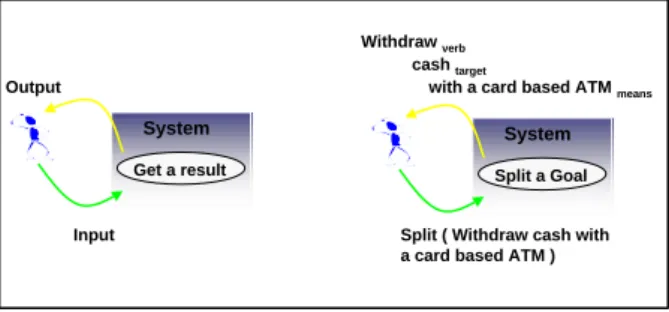
Our suggestion to the Lyee user is to reason in terms of a goal driven interaction as shown in Figure 3. The interaction is meant to be between the user and the system viewed as a black box. The interaction is goal driven in the sense that the user asks the system to achieve the goal he/she has in mind without knowing how the system will do it. The user provides some input and receives the output which corresponds to the expected result. It is the achievement of the goal which produces the output. The input is necessary to achieving the goal. We refer to this goal as the interaction goal.
In generic terms, any interaction is characterised by the user goal ‘Get a result’; it produces an output, given some user input. In the Split example, the user goal is to get
support from the system to decompose a goal statement. Thus, ‘Split a Goal’ is the interaction goal. If, for example, the input is the goal statement ‘Withdraw cash from the ATM’, then the achievement of the goal produces the output i.e. the decomposed form of
the goal : Withdraw verb cash target from the ATM means.
System Get a result Output Input System Split a Goal
with a card based ATM means
Withdraw verb
cash target
Split ( Withdraw cash with a card based ATM )
Figure 3 : The interaction view point Words in interaction
An interaction delineates a number of input and output ‘words’ logically assembled together. The former correspond to meta-model items belonging to the same defined (see below).
In order to systematise the collect of requirements, we identify generic classes of ‘words’ that will be instantiated in any such interaction and represented as items in the requirements formulation. Let us introduce so far three of them :
- Winput : the input provided by the user
- Wresult: the result of the goal achievement - Woutput : : the output displayed to the user
In the ‘Split a Goal’ interaction of Figure 4, Winput is the goal statement given as
input by the user, the result Wresult produced by the achievement of the goal ‘Split a Goal ‘,
is the set {verb, target, means} and the output Woutput presented to the user is identical to the
result, i.e. the set {verb, target, means}. Winput : {goal,}
Wresult : {verb, target, means}.
Woutput = Wresult
As illustrated with the Split example, the set of output words Woutput might be the
same as the set of result words Wresult ; however the semantics is different as the former are
the ones whose values are presented to the user whereas the latter are the ones resulting of the interaction goal achievement.
In addition, as shown underneath a relationship can be established between the Winput and
Wresult:
Wresult Wcmd (Winput )
Indeed, to get the interaction goal achieved, the user has to provide the input and to
give some kind of command (Wcmd)
The concepts of Defined3 and Item
All the words of an interaction shall be represented with the meta-model concept of
Item. The above typology helps identifying the items to be identified and described for a
given interaction.
3
In the following concepts are in italics with a capital as first letter. Instances of concepts are in italics with a small first letter. For example, Item refers to a concept whereas item refers to an instance of the concept Item. A specific item such as goal is in small letter and italics.
Item Wresult, Wcmd, Winput , Woutput
The items belong to the same defined. A Defined is a container of Items logically related to each other. Defined and Items are the keys to expressing user requirements compliant to our meta-model.
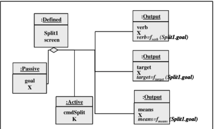
In the Split example there are 5 items, namely goal, cmdSplit, verb, target and
means. All belong to the same defined, Split1. Figure 4 presents the instantiation of the
meta-model for formulating the Items and defined of the Split example. The instance is drawn with the UML object diagram notations.
:Output target X
target=ftarget(Split1.goal)
:Output means X
means=fmeans(Split1.goal)
:Defined Split1 screen :Passive goal X :Active cmdSplit K :Output verb X
verb=fverb(Split1.goal)
:Output target X
target=ftarget(Split1.goal)
:Output target X
target=ftarget(Split1.goal)
:Output means X
means=fmeans(Split1.goal)
:Output means X
means=fmeans(Split1.goal)
:Defined Split1 screen :Defined Split1 screen :Passive goal X :Passive goal X :Active cmdSplit K :Active cmdSplit K :Output verb X
verb=fverb(Split1.goal)
:Output verb X
verb=fverb(Split1.goal)
Figure 4 : Items & Defined of the Split interaction
In the meta-model, the concepts of Defined and Item have attributes: Every defined has a name (Name) and a type (Type) which identifies the physical device of the container (screen, file, database etc..). An item has a name (Name) and a domain (Domain): numeric (9), char(X) and (K) for screen buttons. In the Split example, goal is the name of an item of the defined Split1 which has a string of characters as domain(X).
The meta-model specialises Item into Output and Input. An output is produced by the system whereas an input is captured from the user. Input is further specialised into
Passive and Active. An active input triggers a system action whereas a passive input
represents values captured from the user. A screen button such as cmdSplit in the Split example is an active item whereas goal is a passive one. Both specialisations (Item into Output or Input and Input as Active or Passive) are partitions of the set of items i.e. they are complete and exclusive.
Finally, the concept of Output Item has two specific attributes : Formula and
Condition. The Formula is mandatory whereas the Condition is set by default to true. Due
to the declarative nature of the Lyee approach, calculation dependencies among items do not need to be expressed through conditions. Therefore, only constraints such as validity constraints on input items might become conditions associated to outputs depending on the validity of these inputs. The formula is the calculation rule. In the Split example, the verb
will be associated to the formula, verb = fverb(goal). The function fverb when applied to a
goal statement produces the verb of its goal statement. Housekeeping goals
The achievement of the interaction goal ‘Get a result’ is not always as straight forward as in the case considered so far. It can happen that it requires some additional goals to be fulfilled. We refer to these goals as housekeeping goals. Typical examples are the extension (a) and (b) of the Split case introduced above in the paper. In case (a) the decomposition is stored in the database and in case (b) the goal statement is retrieved from the database. ‘Store Goal Decomposition’ and ‘Retrieve Goal Statement’ are housekeeping goals. They are additional to the interaction goal ‘ Split a Goal’’.
It shall be noticed that there is a fundamental difference between the two types of goals, interaction goal and housekeeping goal. Whereas the ‘Get a result’ type of goal is the essence of the interaction, the housekeeping goals contribute to the performance of a successful interaction but do not determine its purpose. The interaction goal is user-centric whereas the housekeeping goals are system-centric. Following goal decomposition in requirements engineering [3] [6] [23], housekeeping goals can be regarded as sub goals of the interaction goal ‘Get a result’.
However housekeeping goals implies new items and new defineds to be introduced. Let us understand the nature of these items by extending the typology of ‘words’ as defined previously in cases similar to extension (a) of the Split example. A similar reasoning can be done for each type of housekeeping goal [25].
In cases similar to extension (a) of the Split example, words to be memorised in a
persistent manner such as in a database or a file, Windb have to be identified as part of the
user requirements formulation.
Windb Wcmddb (Wdbkey, Woutput)
The above expression characterises the production of Windb. In order to store output
words Woutput in specific database words, Windb, the database key Wdbkey is required and the
user shall activate a command, Wcmddb .
Consequently, new items shall be introduced :
Items Windb, Wcmddb, Wdbkey,
Housekeeping goals lead to specific defineds as they use a specific device distinct from the one characterising the defined of the interaction. In the Split example, the requirement formulation (Figure 5) includes the defined GOAL of type database with the
associated items, goalid, goal, verb, means and target. In contrast, the Wcmddb is part of the
defined associated to the interaction. In the Split example the command button, CmdOK is an item of the defined Split1.
As there are several defineds a precedence relationship between these shall be introduced. The concept of PSG in the meta-model captures this aspect.
The concept of PSG
The meta-model includes the notion of a PSG, the Precedence Succedence Graph to stipulate ordering conditions between Defineds.
As shown in Figure 2, a PSG has Nodes and Links between Nodes. Nodes are classified into Intermediate, Begin and End. Begin and End Nodes are predefined nodes to start and end the program whereas Intermediate Nodes. are related to Defineds .
Links between Nodes are of three different types : Continuous, Duplex and Multiplex Whereas all links indicate the processing order of the related defineds, a continuous link is a forward link between two defineds while duplex /multiplex links are
backward links between two defineds. The choice between a duplex or a multiplex link depends on whether or not data have to be transferred to process the backward defined. In the Split example, the defined GOAL is multiplex- linked to the defined Split1 to get back to an empty Split screen after a goal decomposition was performed. In this case there is no data transfer associated to the backward link to Split1 and therefore, the GOAL-Split1 link in the psgSplit is a multiplex one. It shall be noticed that this information is user driven : it is a user decision to choose an iterative process allowing to capture a goal statement and ask for its decomposition several times.
Finally, the meta-model shows that a Link might have an associated Condition which constraints its occurrence.
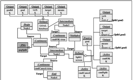
Figure 5 presents the instantiation of the meta-model to formulating the Split a Goal requirements in case (a). The instance is drawn using the UML object diagram notations. It shows that there are two defined, (a) Split1 of type screen, gathering the input and output
items of the interaction and (b) GOAL of type database composed of the items representing
the attributes of the relational table to store the goal decomposition.
Split1 comprises active items (cmdSplit, cmdOK and cmdCancel) whereas GOAL
has only passive items. Some items in Split1 are typed input (cmdSplit, cmdOK,
cmdCancel, goal) whereas the others are output items (verb, target, means). All items in GOAL are typed output as they are produced by the program and stored in the database.
Each of the output items in the defined Split1 are associated with a formula that is its calculation rule. In compliance with the meta-model, the output items of the defined GOAL have formulae which are rules for expressing that the values of the attributes of the database table GOAL are the ones of corresponding items of the defined Split1.
:Output target X
target=ftarget(Split1.goal)
:Output means X
means=fmeans(Split1.goal)
:Defined Split1 screen :Passive goal X :Active cmdOK K :Continuous cmdOK=true :Begin Node1 :Intermediate Node2 :Intermediate Node3 : PSG psgSplit :Multiplex :Continuous Source Target Source Target Source Target :Output goal X :Output target X :Output means X :Defined GOAL database :Output verb X :Output verb X
verb=fverb(Split1.goal)
:Output goalid X :Active cmdSplit K :Active cmdCancel K :End Node4 :Continuous cmdCancel=true Source Target :Output target X
target=ftarget(Split1.goal)
:Output target X
target=ftarget(Split1.goal)
:Output means X
means=fmeans(Split1.goal)
:Output means X
means=fmeans(Split1.goal)
:Defined Split1 screen :Defined Split1 screen :Passive goal X :Passive goal X :Active cmdOK K :Active cmdOK K :Continuous cmdOK=true :Continuous cmdOK=true :Begin Node1 :Begin Node1 :Intermediate Node2 :Intermediate Node2 :Intermediate Node3 :Intermediate Node3 : PSG psgSplit : PSG psgSplit : PSG psgSplit :Multiplex :Multiplex :Continuous :Continuous Source Target Source Target Source Target :Output goal X :Output goal X :Output target X :Output target X :Output means X :Output means X :Defined GOAL database :Defined GOAL database :Output verb X :Output verb X :Output verb X
verb=fverb(Split1.goal)
:Output verb X
verb=fverb(Split1.goal)
:Output goalid X :Output goalid X :Active cmdSplit K :Active cmdSplit K :Active cmdCancel K :Active cmdCancel K :End Node4 :End Node4 :Continuous cmdCancel=true :Continuous cmdCancel=true Source Target
Figure 5 : Formulating the Split requirements through meta-model instantiation
The psgSplit comprises two nodes, Split1 and GOAL in addition to the Begin and
End nodes. They are related by a continuous forward link which is activated in the
processing when the button OK has been pushed and a multiplex link in the backward direction which is processed as soon as the goal decomposition has been stored in the database.
Considering Obstacles to ‘Get a result’
The notion of obstacle has been introduced in requirements engineering by Colin Potts in [19] and further developed in [3] [29] [30] [31]. An obstacle is defined as anything which happens and causes a failure in achieving a goal. From a requirement viewpoint, it is important to identify obstacles as the system under construction shall be prepared to react to obstacle happenings. In our case, identifying the risks of interaction goal failure is a means to complete the requirements related to the interaction.
Considering obstacles to the achievement of ‘Get a result’ leads to the introduction
of new types of words, Wcase i characterised as follows :
Wcase i = P(Woutput ) : f boolean = true
The set of words referred to as Wcase i corresponds to the subset of output words,
Woutput which are produced under a certain condition (f boolean = true).The entire set of output
words to be considered in the interaction is therefore the union of Wcase i.
Let us consider case (c) of the Split example, assuming that the f verb function might
fail if the name of the verb extracted from the goal statement is not in the table of verbs used by this function. The interaction might then, fail in achieving the interaction goal
‘Split a Goal’. Consequently, there are two cases of output :
- case 1 occurs when the verb, target and means items are presented to the user,
whereas
- case 2 occurs when the decomposition cannot be performed; the message
‘Impossible Split’ is shown to the user.
In this case Woutput = Wcase 1 Wcase 2
Wcase 1 = {goal, target, means, verb}
Wcase 2 = {‘Impossible Split’}
An item has to be introduced for every word of each Wcase i.
Figure 6 shows the instantiation of the meta-model to formulating case (c) of the Split example. Two new defineds Scase1 and Scase2 have been added and linked to the
defined Split1 through forward continuous links. These links are labelled with conditions
identifying the two cases, case 1 and case 2. Each of the defineds aggregates the appropriate
items : {goal, target, means, verb, cmdOK} for the defined Scase1 and {M1, cmdOK} for the defined Scase2.
Verb found :Active cmdSplit K :Defined Split1 screen :Passive goal X :Defined Scase1 screen :Defined Scase2 screen :Output M1 :‘Impossible Split’ X :Output verb X :Output target X :Output means X :Begin Node1 :Intermediate Node2 : PSG psgSplit :Continuous Source Target :Continuous cmdSplit=true :Intermediate Node3 Source Target :Continuous cmdSplit=true :Intermediate Node4 Source Verb not found Target :End Node5 :Continuous cmdOK=true Source Target :Continuos cmdOK=true :Active CmdOK K :Active cmdOK K :Output goal X Source Target Verb found :Active cmdSplit K :Active cmdSplit K :Defined Split1 screen :Defined Split1 screen :Passive goal X :Passive goal X :Defined Scase1 screen :Defined Scase1 screen :Defined Scase2 screen :Defined Scase2 screen :Output M1 :‘Impossible Split’ X :Output M1 :‘Impossible Split’ X :Output verb X :Output verb X :Output target X :Output target X :Output means X :Output means X :Begin Node1 :Begin Node1 :Intermediate Node2 :Intermediate Node2 : PSG psgSplit : PSG psgSplit : PSG psgSplit :Continuous :Continuous Source Target :Continuous cmdSplit=true :Continuous cmdSplit=true :Intermediate Node3 :Intermediate Node3 Source Target :Continuous cmdSplit=true :Continuous cmdSplit=true :Intermediate Node4 :Intermediate Node4 Source Verb not found Target :End Node5 :End Node5 :Continuous cmdOK=true :Continuous cmdOK=true Source Target :Continuos cmdOK=true :Continuos cmdOK=true :Active CmdOK K :Active CmdOK K :Active cmdOK K :Active cmdOK K :Output goal X :Output goal X Source Target
Figure 6 : Formulating the Split case (c ) through meta-model instantiation. Compound interaction
In real projects the user has to deal with more gross-grained interactions than the Split interaction drawn in Figure 3. We suggest a distinction between a simple interaction and a compound interaction. The former is associated to one single atomic interaction goal whereas in the latter the goal is an aggregate of interaction sub-goals
Figure 7 is an example of compound interaction where the goal ‘Get Confirmed
Booking’ is an aggregate of two sub-goals : ‘Request for Booking’ and ‘Confirm & Pay’.
The request parameters are the inputs necessary to achieve the first sub goal which results in an offer to the customer. This offer is the input for the achievement of the second sub goal.
Customer
Customer Get Confirmed
Booking Confirmed Booking
Request for booking (request parameters) Confirm & Pay (offer parameters)
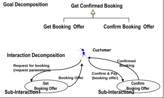
The notion of AND decomposition of a goal is well known in requirements engineering [5] [6] [19] [22] and business process modelling [3] [11] [14] [18] [26] and seems to fit our needs. The interaction goal of a compound interaction is decomposable in two or more ANDed sub-goals. As shown in Figure 9, the interaction goal ‘Get Confirmed Booking’ is decomposable in two sub-goals ‘Get Booking Offer’ and ‘Confirm Booking
Offer’
Goal Decomposition Get Confirmed Booking
Get Booking Offer Confirm Booking Offer
Interaction Decomposition CustomerCustomer
Get Booking Offer
Booking Offer
Confirm & Pay (booking offer)
Confirm Booking Offer
Request for booking (request parameters)
Confirmed Booking
Sub-Interaction1 Sub-Interaction2
Figure 8 : Decomposition of the ‘Get Confirmed Booking’ interaction
It is important to notice that sub-goals are interaction goals. In other words, the compound interaction can be seen as a sequence of atomic interactions, each of them corresponding to one sub-goal of the compound interaction goal. This is exemplified in Figure 8 that shows the compound interaction to ‘Get a Confirmed Booking’ as composed of two interactions, the first one to ‘Get Booking Offer’ and the second one to ‘Confirm
Booking Offer’. Each of these interactions follows the pattern explained above and might
include housekeeping goals. Each of these will have to be scrutinised as explained before to identify the involved items and defineds.
To sum up, the user centric layer of the meta-model identifies three key concepts,
Defined, Item and PSG. These three concepts are used to express the set of domain
dependent requirements and this expression is necessary and sufficient to derive the Lyee software requirements. Items are the essence of Lyee user requirements, the external form of Lyee internal words. A Defined is a group of items that are conceptually related to one another and are bound together in a simple or compound interaction. In addition to the
Defineds flowing from the interaction, housekeeping goals introduce complementary defineds that require the use of devices such as databases, files or Internet communications.
The concept of PSG captures the ordering of the defineds required by the user.
From a semantic viewpoint, this paper proposes to relate the user-centric requirements to the notion of an interaction and introduces an interaction frame with a
typology of ‘words’ to reason systematically about the requirements implied by this
interaction. It was shown that a complex interaction case can be mastered using a decomposition mechanism that breaks down the compound interaction in ANDed atomic interactions. This introduces the problem of guiding the process to capture user-centric requirements compliant with the meta-model. This problem is dealt with in the next section.
4. Guiding the Requirements Capture
Any method is defined as composed of a product model and a process model [20]. Whereas section 3 was dealing with the product model of the Lyee method, we consider here the
process aspect of the method. Our aim is to systematise the capture of user-centric
requirements and their formulation in terms which comply with the upper layer of the meta-model as presented in the previous section. Ultimately, our goal is to implement a software assistant to support the capture and formulation of these requirements.
Our process modelling approach is Pattern based. The concept of a pattern has been introduced by Alexander in architecture [2] and borrowed by IT engineers to capture software design knowledge. According to Alexander, a pattern refers to ‘a problem which occurs again and again in our environment and describes the core of the solution to that problem, in such a way that you can use this solution a million times over, without ever doing it the same way twice’. The key idea of a pattern is thus, to associate a problem to its
solution in a well identified context. The formulation of the problem and of its associated
solution are generic.
We identified ten typical situations (the problem) in Lyee user-centric requirements capture (the context) and associate to them ten guidelines (the solution) to help in the requirements elicitation and formulation. We coupled the situation and associated guideline in a Requirement Pattern and therefore, the process model takes the form of a Catalogue of
Requirements Patterns.
Each pattern captures a requirement situation and guides the formulation of the requirement in compliance with the requirement meta-model. In fact each pattern tells for the given situation, what are the concepts of the meta-model to instantiate and how, which are the attributes that have to be considered and what are the links between concepts that must be instantiated.
The ten patterns will be applied again and again in the different software projects using Lyee. Even if actual situations are different from one project to another, each of them should match one pattern situation and the pattern will bring the core solution to the requirements capture problem raised by this situation.
Identifying generic activities of requirements capture in an atomic interaction
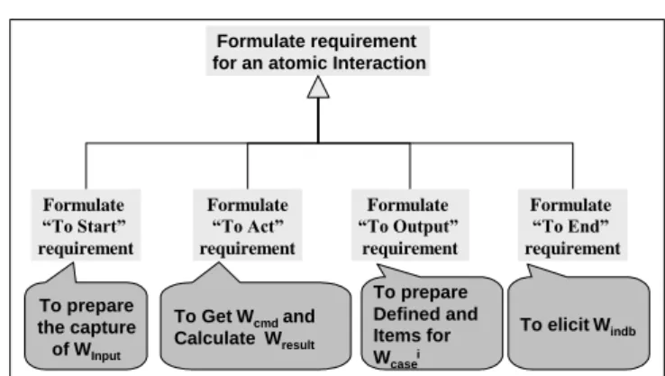
In order to systematise the requirements capture, we first founded our reasoning on the notion of atomic interaction and investigate the possibility to identify generic activities of requirements capture within the context of an atomic interaction. We end up with the view that the capture of requirements related to an atomic interaction comprises four activities to, respectively:
- Start the interaction (To Start requirement) - Perform the action (To Act requirement)
- Prepare the output ( To Output requirement)and, - End the interaction (To End requirement)
Formulate requirement for an atomic Interaction
Formulate “To Start” requirement Formulate “To Act” requirement Formulate “To Output” requirement Formulate “To End” requirement To prepare the capture of W Input To Get Wcmdand Calculate W result To prepare Defined and Items for Wcasei To elicit Windb
Figure 9 : Generic activities of requirements capture in an atomic interaction
As shown in Figure 9, each of these activities is linked to the ‘word’ typology introduced in section 3 as each activity is associated to one type of ‘words’. The requirement activity is concerned with the elicitation and definition of these ‘words’, their grouping in defineds and the positioning of those in the PSG of the interaction.
- The To Act requirement is concerned by the elicitation of the Wcmd and the
calculation of Wresult
- The To Output requirement shall help eliciting and defining Wcase i
- Finally, the To End requirement considers Windb
Identifying typical situations in requirements capture
The relationship between a requirement activity and its associated type of word was essential to identify generic situations for requirements capture. For instance, we identified
two different situations dealing with the capture of W input : either the input value is directly
captured from the user or it is indirectly captured through the satisfaction of a housekeeping goal. In the Split example this corresponds to the initial case and case (b), respectively. In the initial case the user provides the goal statement whereas in case (b) it provides the
goalid which is used to retrieve the goal in the database table.
We identified two generic situations for each of the four generic activities of requirement capture introduced above. These situations are described in the Table1 below.
Situation Requirement Activity Situation Characterisation
S2 To Start W input are captured directly from the user
S3 To Start W input are captured indirectly through some
housekeeping goal to retrieve the input value from a database or a file
S1 To Act W result are calculated by simple formulae which
do not require the calculation of intermediate words
S8 To Act W result are calculated by complex formulae
which do require the calculation of intermediate words and possibly the access to data in a file or database.
S6 To Output There is no obstacle neither in the capture of
Winput nor in the production of W result
S7 To Output A number of different cases of output
production shall be considered due to possible obstacles either in the capture of W input or in
the production of W result
S4 To End The interaction ends normally without
additional housekeeping activity.
S5 To End Some housekeeping activity shall be performed
such as storing part or the totality of Woutputs
Table 1 : Generic situations in requirements capture
It shall be noticed that the two situations of each activity are orthogonal. Given an interaction and one requirement activity , let say ‘To Act’ either S1 or S8 will be true but not both as the same time.
Identifying requirements patterns
- Atomic interaction patterns
To each of the 8 situations of requirement capture presented above, we define a guideline that helps in the performance of the requirement activity. As the result of any of these requirements activities is an instantiation of the meta-model concepts, guidance tells which items shall be introduced, to which defineds they must be associated and how these
defineds must be positioned in the PSG. Every guideline provides exactly this type of
knowledge : given the situation at hand, the guideline advises on items, defineds and their
We couple the situation and the guideline in a pattern, namely a Requirement
Pattern. Figure 10 shows the 8 patterns corresponding to the 8 situations described in
Table1. These are atomic patterns in the sense that they do not call for applying other patterns.
Formulate requirement for an atomic interaction
P2 P3 P1 P8 P6 P7 P4 P5 Immediate Start Prerequisite for Start Simple Word Complex Word Single Output Multiple Output Simple End Compound End
“To Start” “To Act” “To Output” “To End”
Figure 10 : Requirements Patterns for an atomic interaction
These 8 patterns provide advice to capture and formulate requirements for each of the generic requirements activities:
- P2 &P3 support the ‘ToStart’ requirements activity, i.e. the setting of requirements to ensure that Winput will be properly defined
- P1 & P8 help in the elicitation of requirements which guarantees that Wresult can be calculated by the Lyee program
- P6 &P7 advice in discovering obstacles to interaction goal achievement and to formulate the appropriate items, defineds and PSG links for handling these obstacles in the Lyee program.
- P4 &P5 ensure that the interaction will end correctly and that housekeeping goals will be taken care of.
- Composite pattern for atomic interaction
Each of the previous 8 patterns deals with one single requirement activity whereas to get the complete set of requirements for a given problem, the requirements engineer has to perform one of each type of activity. The complete set of requirements requires that each of the following be performed once: ‘To start’, ‘To Act’, ‘To Output’ and ‘To End’.
To obtain advice on this, a new pattern, Pattern P9, is introduced. As shown in Figure 11, the requirement pattern P9 is a compound pattern composed of the 8 atomic patterns, P1 to P8.
Solution :
1Apply patterns as shown below in the left to right order :
2. When multiple choice is provided select the pattern based on the situation P2 P3 P6 P7 P4 P5
start output end
1..* act P1 P8 sequence 1..* multiplicity Multiple choice
Figure 11 : The compound requirement pattern P9
P9 simply advises that one pattern for each of the four activities needs to be applied to complete one interaction requirements formulation. The choice of the right pattern to apply for each activity is based on the situation at hand. Since the situations of the two candidate patterns of any activity are orthogonal, the decision making is facilitated. For instance, in the simple case of the Split example (get the goal statement and outputs the
goal decomposition), P2 is applicable as the input is directly got from the user; P1 must be applied as the decomposition function produces the goal decomposition directly from the goal statement; P6 is the right pattern because there is no obstacle either in getting the input or in calculating the result and P4 is applicable in this case as there is no additional task to perform than displaying the goal decomposition to the user.
Thus, for a given interaction, the requirements process will consist of a path within P9. For instance, P2, P1, P6, P4 is the path for dealing with the basic Split example whereas P3, P8, P7, P5 is the path for the extended Split example (combining (a), (b) and (c)).
- Composite pattern for compound interaction
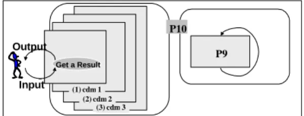
Finally, the requirement pattern P10 deals with a compound interaction as introduced in the previous section. As shown in Figure 12, P10 is a composite pattern which calls for the iterative application of P9.
As suggested by the figure, the pattern gives advice on how to decompose a
compound interaction into atomic
interactions to which the pattern P9 should be applied. In fact, the pattern helps in recognising that the interaction is not an atomic one in the first place.
P10 (3) cdm 3 (2) cdm 2 (1) cdm 1 P9 Get a Result Input Output
Figure 12 : The composite requirement pattern P10
5. Conclusion
The UP1 activity presented here relies on meta-modelling. Meta-modelling has been used in Information Systems as a way of developing abstractions of methods to aid in method understanding, evaluation and comparison. In extending this to Lyee we expected to gain a better understanding of how the Lyee method generates programs from given software requirements. Indeed the lower of the two layers of our meta-model achieved this purpose. The upper layer added a new abstraction level which makes it possible to deal with user requirements and not with low level software requirements. With this capability comes the possibility of generating Lyee programs directly from user requirements. The next step to be taken is to formalise the mapping rules between the two sets of concepts.
Meta-modelling addresses both, process and product aspects of methods. The meta-model presented in this paper is a product meta-meta-model. To complete the formalisation of the method it is necessary to also model the way-of-working. The paper introduced the pattern approach and the ten patterns which are currently under development to support the acquisition of user requirements. Each pattern identifies a generic situation in user requirements capture and proposes a solution to elicit and formulate the requirement typical of this situation. The next step will be to validate the pattern through extensive experiments and to develop a CASE tool to guide the requirements engineers in the application of patterns.
6. References
[1] N.Ahituv, ‘A Meta-Model of information flow : a tool to support information theory’, Communications of the ACM, 30(9), pp781-791, 1987.
[2] C. Alexander, S. Ishikawa, M. Silverstein, M. Jacobson, I. Fiksdahl-King, S. Angel, ‘A Pattern
Language’, Oxford University Press, New York, 1977.
[3] A.I. Anton, W. M. Mc Cracken, C. Potts, ‘Goal decomposition and scenario analysis in business process
reengineering’, Proceedings of the 6th International Conference CAiSE’94 on Advanced Information
[4] S. Brinkkemper, K. Lyytinen, R. Welke (eds): ‘Method Engineering : Principles of Method Construction
and Toll Support’, Chapman & HALL, London, UK, 1996
[5] : J. Bubenko, C. Rolland, P. Loucopoulos, V. De Antonellis, ‘Facilitating, ‘Fuzzy to Formal’
Requirements Modelling’ , Proc. of the First International Conference on Requirements Engineering,
Colorado Springs, Colorado, 1994.
[6] A. Cockburn, ‘Structuring use cases with goals’, 1995 http://members.aol.com/acocburn/papers/usecases.htm
[7] Series of Proceedings of CAISE/IFIP8.1 International Workshop on Evaluation of Modeling Methods in Systems Analysis and Design (EMMSAD).
[8] J.C. Grundy, J.R. Venable, ‘Towards an integrated environment for method engineering’, Proc. IFIP WG 8.1 Conf on ‘Method Engineering’, Chapman and Hall, pp 45-62, 1996.
[9] F. Harmsen, S.Brinkkemper, ‘Design and implementation of a method base management system for
situational CASE environment’, Proceedings of the 2nd
APSEC Conference, IEEE Computer Society Press, PP 430-438, 1995.
[10] A.H.M. Ter Hofstede, ‘Information modelling in data intensive domains’, Dissertation, University of Nijimegen, The Netherlands 1993.
[11] R.L. Hsiao and R.J. Ormerod, ‘A new perspective on the dynamics of information technology-enabled
strategic change’, Information Systems Journal, Blackwell Science, Vol. 8. No. 1, pp. 21-52, 1998.
[12] M. Jarke, C. Rolland, A. Sutcliffe, R. Domges, ‘The NATURE requirements Engineering’. Shaker Verlag, Aachen 1999.
[13] S. Kelly, K. Lyyttinen, M. Rossi, ‘MetaEdit+: A fully configurable, multi-user and multi tool CASE and
CAME environment’, Proc. CAiSE 96 Conference, Springer Verlag, 1996.
[14] J. Lee, ‘Goal-Based Process Analysis: A Method for Systematic Process Redesign’, Proceedings of Conference on Organizational Computing Systems, , Milpitas, CA, pp. 196-201, 1993.
[15] MOF Specification, OMG document ad/97-08-14, revised submission, September 1, 1997.
[16] F. Negoro, ‘Methodology to Determine Software in a Deterministic Manner’, Proceeding of ICII, Beijing, China, 2001.
[17] F. Negoro, ‘A proposal for Requirement Engineering’, Proceeding of ADBIS, Vilnius, Lithuania, 2001. [18] M.A. Ould ‘Business Processes - Modelling and Analysis for Re-engineering and Improvement’, John Wiley and Sons, Chichester, UK, 1995.
[19] C. Potts, K. Takahashi, A.I. Anton, ‘Inquiry-based requirements analysis’, IEEE Software 11(2), pp. 21-32, 1994.
[20] N. Prakash, ‘On Method Statics and Dynamics’, Information Systems, Vol 24, No 8, pp 613-637, 1999. [21] C. Rolland, C. Souveyet, M. Moreno, ‘An Approach for Defining Ways-of-Working’, Information Systems Journal, 1995.
[22] C. Rolland, C. Ben Achour, C. Cauvet, J. Ralyté, A. Sutcliffe, N.A.M. Maiden, M. Jarke, P. Haumer, K. Pohl, Dubois, P. Heymans, ‘A proposal for a scenario classification framework’. Requirements Engineering Journal Vol 3, No1, 1998.
[23] C. Rolland, N. Prakash, A. Benjamen : ‘A Multi-Model Vew of Process Modelling’, Requirements Engineering Journal (4)(4), pp169-187, 1999.
[24] M. Saeki, K. Wen-yin, ‘Specifying Software Specification and Design Methods’, Proc. CAISE 94, LNCS 811, Springer Verlag, pp 353-366, Berlin, 1994.
[25] TR5.1: ‘L’Ecritoire Linguistic Approach : Concept Definition and Implementation’. Technical Report, University Paris 1, C.R.I, mars 2002.
[26] E. Yu, J. Mylopoulos, ‘Using goals, rules and methods to support reasoning in business process
reengineering’. Proceedings of the 27th Hawaii International Conference System Sciences, Maui, Hawaii,
January 4-7, Vol. IV pp. 234-243, 1994.
[27] S. Si-Said, G. Grosz, C. Rolland, ‘Mentor, A Computer Aided Requirements Engineering Environment’, Proceedings of the 8th CAISE Conference. Challenges in Modern Information Systems, Heraklion, Crete, Greece, May 1996.
[28] K.Smolander, K.Lyytinen, V.Tahvanainen, P.Martiin : ‘Meta-Edit - A Flexible Graphical Environment
for Methodology Modelling’, Proceedings of the 3rd International Conference in Advanced Information
Systems Engineering.
[29] A. Dardenne, A.v. Lamsweerde, and S. Fickas , ‘Goal-directed Requirements Acquisition’, Science of Computer Programming, Vol. 20, 1993.
[30] A.v. Lamsweerde, R. Dairmont, P. Massonet; ‘Goal Directed Elaboration of Requirements for a Meeting
Scheduler : Problems and Lessons Learnt’, in Proceedings of Requirements Engineering, pp 194 –204,1995.
[31] A.G. Sutcliffe, N.A.M. Maiden, S. Minocha, D. Manuel, ‘Supporting Scenario-based Requirements
Engineering’, Transaction of Software Engineering, Special Issue on Scenario Management, Vol. 24, No. 12,