HAL Id: in2p3-00377124
http://hal.in2p3.fr/in2p3-00377124
Submitted on 21 Apr 2009HAL is a multi-disciplinary open access archive for the deposit and dissemination of sci-entific research documents, whether they are pub-lished or not. The documents may come from teaching and research institutions in France or abroad, or from public or private research centers.
L’archive ouverte pluridisciplinaire HAL, est destinée au dépôt et à la diffusion de documents scientifiques de niveau recherche, publiés ou non, émanant des établissements d’enseignement et de recherche français ou étrangers, des laboratoires publics ou privés.
Preliminary implementation for the new SPIRAL2
project control system
P. Gillette, C. Haquin, E. Lécorché, D. Touchard, J.F. Denis, F. Gougnaud,
J.F. Gournay, Y. Lussignol, P. Mattei, P. Graehling, et al.
To cite this version:
P. Gillette, C. Haquin, E. Lécorché, D. Touchard, J.F. Denis, et al.. Preliminary implementation for the new SPIRAL2 project control system. 7th International Workshop on Personal Computers and Particle Accelerator Controls - PCaPAC08, Oct 2008, Ljubljana, Slovenia. pp.165-167, 2008. �in2p3-00377124�
PRELIMINARY IMPLEMENTATIONS FOR THE NEW SPIRAL2 PROJECT
CONTROL SYSTEM
P. Gillette, C. Haquin, E. Lécorché, D. Touchard and the Ganil control group (Ganil / Caen, France)
J.F. Denis, F. Gougnaud, J.F. Gournay, Y. Lussignol, P. Mattei (CEA-IRFU / Saclay, France)
P. Graehling, J. Hosselet, C. Maazouzi, C. Olivetto (CNRS-IPHC / Strasbourg, France)
Abstract
The Spiral2 project consists of a new facility to provide high intensity rare ions beams. It is based on a primary beam driver accelerator (RFQ followed by a superconducting linac) and a rare ion production process delivering the beam either to a low energy experimental area or to the existing Ganil facility. From October this year, one ion source coupled with a first beam line section will be in test; then, the injector (ion and deuteron sources, RFQ) will be tested by the end of 2010 so the whole accelerator should be commissioned by the end of 2011; the first exotic beams being planned one year later. The accelerator control system design results from the collaboration between several institutes and Epics has been chosen as the basic framework. The paper therefore presents the main choices: MVME5500 CPUs, VME I/O boards, VxWorks, Siemens PLCs, Modbus field buses, EDM screens and Java applications, Linux PCs, use of a LabView/Epics gateway… Specific topics are the evaluation of the XAL environment, an Epics design to address the power supplies, an emittance measurement system, the development of a beam profiler interface and the investigation for a triggered acquisition system.
THE SPIRAL2 PROJECT
General Overview
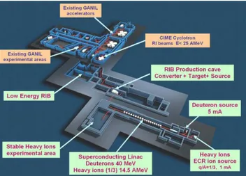
The Spiral2 project ([1], [2]) aims to build a new facility providing rare ion beams (RIB), it will be installed on the Ganil site (Caen, France) and will be coupled with the Ganil existing complex as shown on Figure 1:
Figure 1: Installation of the Spiral2 facility within the Ganil complex.
First, a primary beam will be produced, according to different particles to be accelerated as shown on Table 1:
Table 1: The Spiral2 Primary Beams.
Beam p+ D+ Ions Ions
Q/A 1 1/2 1/3 1/6
Imax (mA) 5 5 1 1 Wmin (MeV/A 2 2 2 2 Wmax (MeV/A) 33 20 14,5 8,5 CW beam power (kW) 165 200 44 48
This beam will be therefore either sent to a new stable experimental area or to the RIB production facility able to deliver the rare ion beam either to a new low energy beam experimental area or to the existing Ganil facility.
The Linac Based Accelerator
The accelerator consists of ions or deuterons ECR sources, a RFQ to pre-accelerate the beam up to 0,75 Mev/A then the superconducting Linac. Both the RFQ and the Linac cavities are operated at 88.05 MHz; the Linac is composed of two beta quarterwave resonators families:12 β=0,07 modules equipped with one cavity and 7 β=0,12 modules, each one having two cavities. These cryomodules are separated by warm focusing sections, integrating quadrupoles doublets and diagnostic boxes.
Figure 2: Accelerator schematic layout.
The RIB Facility
The RIB production process will be achieved through target ion/source systems using different techniques. A first way is based on the use of a carbon converter generating neutrons from the deuterons beam impinging on a uranium carbide target; the neutron flux therefore generates fission reactions so producing a large variety of rare isotopes. An other alternative consists in sending other types of beams on targets/sources assemblies so producing rare ions by different reaction types. So, a 1+ ions beam is produced and sent either to an identification system, a new low energy experimental area or a 1+/N+ charge booster. Lastly the N+ rare ion beam will be transported to the existing CIME cyclotron accelerating
Proceedings of PCaPAC08, Ljubljana, Slovenia WEP001
Classical Topics Status Reports and Control System Overviews 165
the beam up to 25 MeV/A before finally being sent to the Ganil experimental areas.
Milestones
The project has been approved in May 2005 and relies on the collaboration between many French, European and international laboratories. The commissioning of the driver accelerator is planned by the beginning of year 2012 so that the availability of rare ion beams is presently considered for 2013. Within this collaboration policy, intermediate tests for the accelerator will be performed:
• The q/a=1/3 ions source and the first part of the coming out low energy beam transfer line (LEBT1) will be tested by the beginning of next year (2009) at CNRS-LPSC (Grenoble).
• In parallel, first tests of the deuterons source will start to be carried out at CEA-IRFU (Saclay). Then this process will be extended as the so-called “Injector” part (deuterons source, low energy beam transport line LEBT2, RFQ, part of the medium energy beam transport line MEBT) will be installed and tested at CEA-IRFU (mid-2010) before being dismounted and transferred (2011) to Ganil at Caen.
THE EPICS BASED ACCELERATOR
CONTROL SYSTEM
Collaborations
Like the whole project organisation, the accelerator control system design results from the collaboration of several institutes [3]. Beside of its own implementations, obviously Ganil as the installation site will have to coordinate and to integrate developments performed by the two other laboratories involved into the control system collaboration: CEA-IRFU (Saclay) and CNRS-IPHC (Strasbourg). Because of its previous experience running Epics ([4], [5]), IRFU is in charge of first providing the global Epics software architecture then developing specific subsystems and is also globally responsible of the injector control system as it will be first installed and tested at Saclay, so being nearby. IPHC like Ganil was a new Epics user and joined the collaboration as being in charge of an intermediate test bench to qualify the beam at the RFQ output; this platform integrates many beam diagnostics to be interfaced.
The Ganil facility is presently successfully operated within the so-called home made “Ganiciel” control system ([6]) based on Ada software being executed both at the Linux level (operator consoles and servers) and the real-time environment (VME crates running the VxWorks operating system). Nevertheless Epics was chosen for the Spiral2 driver control system because of its wide use among the accelerator community and to be a common environment for the three laboratories. As far as the RIB control system is concerned, a study has still to be performed as the two control systems will have to be coupled together so probably needing an evolution of the Ganiciel interface layer.
Main Technical Options
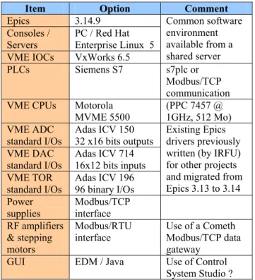
Table 2: The Accelerator Control System Main Options.
Item Option Comment
Epics 3.14.9 Consoles /
Servers PC / Red Hat Enterprise Linux 5 VME IOCs VxWorks 6.5
Common software environment available from a shared server PLCs Siemens S7 s7plc or Modbus/TCP communication VME CPUs Motorola
MVME 5500 (PPC 7457 @ 1GHz, 512 Mo) VME ADC standard I/Os Adas ICV 150 32 x16 bits outputs VME DAC
standard I/Os Adas ICV 714 16x12 bits inputs VME TOR standard I/Os Adas ICV 196 96 binary I/Os Existing Epics drivers previously written (by IRFU) for other projects and migrated from Epics 3.13 to 3.14 Power supplies Modbus/TCP interface RF amplifiers & stepping motors Modbus/RTU interface Use of a Cometh Modbus/TCP data gateway
GUI EDM / Java Use of Control System Studio ?
FIRST TESTS AND IMPLEMENTATIONS
Power Supplies Interface
It has been decided at an early stage of the design to consider Ethernet as the standard field bus to interface the power supplies, using Modbus/TCP at the application layer. So the specific LEBT1 line power supplies have been ordered, featuring a dedicated mapping to be opened for future needs or extensions. For off the shelf power supplies, the Ganil power supplies group developed a home-made Modbus/TCP interface card.
An appropriate Epics records database has been designed using VDCT so first tests (IOC first on Linux then VxWorks) have been successfully performed. More details about this development can be found in [7].
Evaluation of a Fast Triggered Acquisition
System
The accelerator will be a CW machine but, because of the beam power, the commissioning as well as the tuning will have to be performed within a pulsed mode with a duty cycle up to 10-4 (typically one 100µs pulse at 1 Hz).
To get the beam intensity, Faraday cups or DC current transformers (DCCT) will be used [8] implying an acquisition process to be triggered according to the beam pulse characteristics.
The foreseen bandwidth for signals is about 50 KHz. Our first requirements for this acquisition board were a sampling rate of 1 MSamples/s, an external trigger to synchronize the acquisition with the beam pulse and an at least 14 bits resolution for the ADCs. Another constraint
WEP001 Proceedings of PCaPAC08, Ljubljana, Slovenia
Classical Topics 166
was to select a VME form factor board. These major specifications lead us to choose this VME boards configuration: an ICV178 16 bits resolution, 8 analog inputs and 1,2.MSamples/s connected to a controller board ICV108 via the I/O lines of P2. The ICV108 comprises an external trigger, a RAM buffer of 4 Mbytes and runs in “single event” or “flip flop” modes. The block transfer rate could reach 76 Mbytes/s in VME64. The different available modes to use these boards and the software development are in progress.
Emittance Measurement System
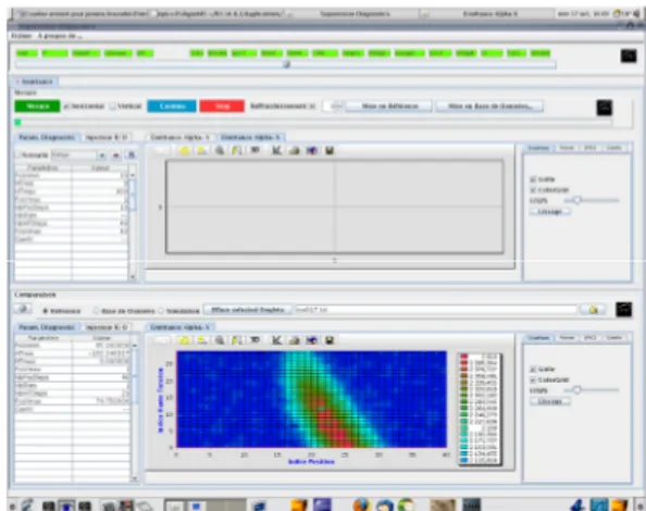
Similar as the beam test bench one, three transverse emittance measurement systems (Allison scanners) will be installed within the low and medium energy beam transfer lines. A first implementation of the system has been performed and real tests have been carried out at CNRS-LPSC. It worked fine as shown on the screen snapshot Figure 3, displayed by a Java application addressing the VME IOC through the CAJ package (the configuration being achieved by an EDM application).
Figure 3: Screen snapshot of the emittance Java display. The final design will make use of specific VME modules such as the Oregon OMS MaxV 4000S card to drive Brushless motors and an ISEG 202 M board to provide a high voltage output, both of them having an existing Epics driver. When validated, the fast triggered acquisition system described above will be integrated into the measurement acquisition system.
Investigation for High Level Applications
Beside of EDM screens used for the basic GUI interfaces to equipment, high level applications will have to be developed in Java language within the Eclipse IDE. Some investigation for the high level applications development is in progress, including an evaluation of the XAL environment [9]. So, some basic tests were successfully done based on this XAL framework and the evaluation has to be continued according to the Spiral2 specific tuning requirements. Also a link with the particle trajectories Tracewin [10] simulation code will have to be considered in the same time with the objective to provide an on-line optimisation and tuning of many correlated parameters by using the calculation TraceWin program to determinate the appropriate values to be applied.
Beam Profiler Interface
A new electronic board to perform the beam profiler measurement is currently under design by the Detectors and Technologies for Physics Section at Ganil. The acquisition is done by an FPGA Altera processor while a ColdFire 5282 µcontroller is in charge of the data processing; it also communicates via an I2C bus with a daughter board under the control of a µprocessor having to handle the auxiliary controls of the beam diagnostic: high voltage settings, vacuum control, device insertion …
Communication with the control system will be achieved through the use of a Modbus/TCP connection. IOC interface is presently under consideration.
Ion Beam Tests Environment
As the ion source coupled with part of the LEBT1 line is going to be tested by the beginning of 2009, this will be the opportunity to merge the different developments performed by the three laboratories involved into the collaboration. Later, some new components and functionalities of the definitive control system will be added progressively, according to the tests progress.
CONCLUSION & PERSPECTIVES
As described in this paper, the building blocks of the accelerator Epics based control system are under way, although a lot of work has still to be done. Up to now, most of our efforts have been concentrated towards the injector control system design. The next step will consist in considering topics related to the whole accelerator: beam diagnostics interface, low level RF integration, high level applications, database organisation.Also the preliminary study for the RIB control has to be launched.
REFERENCES
[1] T. Junquera et al. “Status of the Construction of the Spiral2 Accelerator at Ganil” Linac 2008.
[2] P. Bertrand, M.H. Moscatello, “The advancement of Spiral2 project” Cyclotrons 2007.
[3] E. Lécorché et al. “First steps towards the new Spiral2 project control system” Icalepcs 2007.
[4] J.F. Gournay, “Quench data acquisition and slow control for the superconducting magnet of the Compass experiment” Icalepcs 2005.
[5] F. Gougnaud et al., “The control system for the MIRI imager Ground Support Equipment” Icalepcs 2005. [6] L. David and the Ganil control group, “Linux
migration of the Ganil control system” Icalepcs 2005. [7] D. Touchard, “A Modbus/TCP based power supply
interface” PCaPAC 2008, this workshop.
[8] C. Jamet et al., “Injector diagnostics overview of Spiral2 accelerator”, Dipac 2007.
[9] T. Pelaia II et al., “XAL Status” Icalepcs 2007.
[10] D. Uriot, N. Pichoff, “New implement in TraceWin/Partran codes: integration in external field map”, PAC2003.
,
,
,
Proceedings of PCaPAC08, Ljubljana, Slovenia WEP001
Classical Topics Status Reports and Control System Overviews 167