HAL Id: in2p3-00309538
http://hal.in2p3.fr/in2p3-00309538
Submitted on 6 Aug 2008HAL is a multi-disciplinary open access
archive for the deposit and dissemination of sci-entific research documents, whether they are pub-lished or not. The documents may come from teaching and research institutions in France or
L’archive ouverte pluridisciplinaire HAL, est destinée au dépôt et à la diffusion de documents scientifiques de niveau recherche, publiés ou non, émanant des établissements d’enseignement et de recherche français ou étrangers, des laboratoires
Power loss estimation in the Electrostatic Separators of
the ILC alternative head-on scheme at 500 GeV in the
center-of-mass
J. Brossard, P. Bambade, O. Napoly
To cite this version:
J. Brossard, P. Bambade, O. Napoly. Power loss estimation in the Electrostatic Separators of the ILC alternative head-on scheme at 500 GeV in the center-of-mass. 2007, pp.1-4. �in2p3-00309538�
Power loss estimation in the Electrostatic Separators of the ILC
alternative head-on scheme at 500 GeV in the center-of-mass
J. Brossard1, P. Bambade1, O. Napoly2 1LAL, Univ Paris-Sud, IN2P3/CNRS, Orsay, France
2CEA, Saclay, France
September 10, 2007
Abstract
This memo presents the power loss estimation in the Electrostatic Separators of the ILC alternative head-on scheme at 500 GeV in the center-of-mass, for the Nominal and High Luminosity beam parameters set, induced both by beam particles and radiative Bhabha processes.
Computation
The computation of the power losses has been realized using DIMAD software in the alternative head-on scheme [1] extraction line. In order to achieve an accurate estimation of the power losses, high statistics macro-particle distributions [2,3] have been tracked. Table 1 shows the number of macro-particles (resp. particles) tracked for the beam (resp. radiative Bhabha processes). With these beam statistics the upper limit of the minimal power deposition which can be obtained is 1.8 W (corresponding power deposition from one charged beam macro-particle at 250 GeV). For Nominal (resp. High Luminosity) beam parameters, the total radiative Bhabha processes is about 72 W (resp. 147 W). The minimal power deposition is much lower in this case, around 0.07 W (resp. 0.03 W).
Number of macro-particles or particles Beam 6 183 275 (macro-particles) Nominal
Radiative Bhabha processes 5 286 120 (particles)
Beam 5 983 849 (macro-particles) High Luminosity
Radiative Bhabha processes 11 188 544 (particles) Table 1 : Statistics used in the computation [2,3].
The results are shown in Table 2 and Table 3 for the 7 Electrostatics Separators (ES) needed in the present design, both for full and vertically split electrodes. The full horizontal gap between electrodes of each ES device is 100 mm, and their total vertical extent is 50 mm (theses dimensions are used in DIMAD software to define the transverse aperture of each ES device). In the case of calculation with splits electrodes, an additional vertical gap of up to 50 mm is introduced in the middle of each electrode.
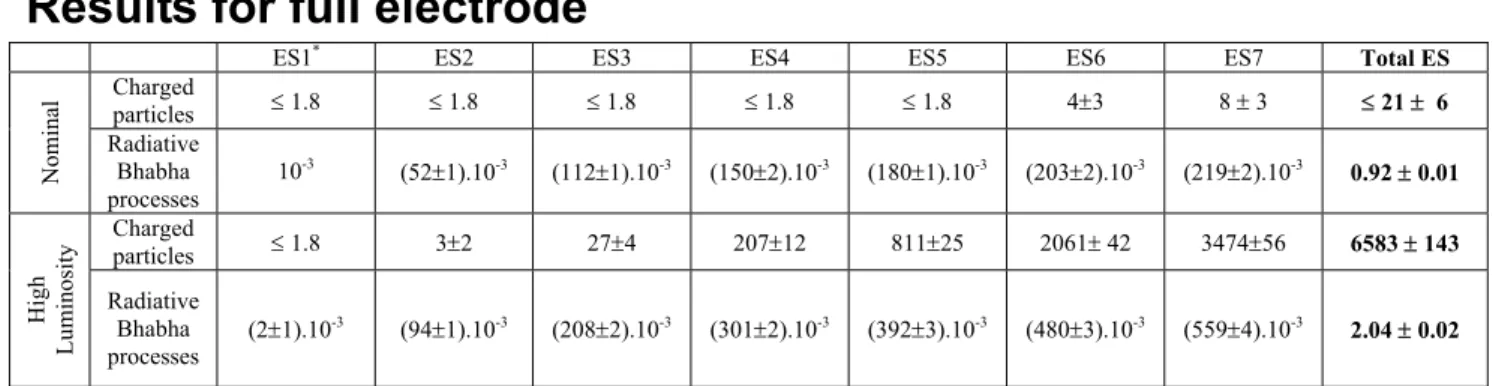
Results for full electrode
ES1* ES2 ES3 ES4 ES5 ES6 ES7 Total ES
Charged particles ! 1.8 ! 1.8 ! 1.8 ! 1.8 ! 1.8 4"3 8 " 3 ! 21 " 6 Nominal Radiative Bhabha processes 10-3 (52"1).10-3 (112"1).10-3 (150"2).10-3 (180"1).10-3 (203"2).10-3 (219"2).10-3 0.92 " 0.01 Charged particles ! 1.8 3"2 27"4 207"12 811"25 2061" 42 3474"56 6583 " 143 High L um in os it y Radiative Bhabha processes (2"1).10 -3 (94"1).10-3 (208"2).10-3 (301"2).10-3 (392"3).10-3 (480"3).10-3 (559"4).10-3 2.04 " 0.02
Table 2 : Power losses (in W) in the 7 ES devices, for full electrodes.
Results for 50 mm full gap split electrode
ES1 ES2 ES3 ES4 ES5 ES6 ES7 Total ES
Charged particles ! 1.8 ! 1.8 ! 1.8 ! 1.8 ! 1.8 ! 1.8 ! 1.8 ! 13 Nominal Radiative Bhabha processes 10-3 2.10-3 3.10-3 3.10-3 3.10-3 4.10-3 4.10-3 0.02 Charged particles ! 1.8 2 4 6 23 26 36 ! 99 High L um in os it y Radiative Bhabha processes 2.10-3 7.10-3 9.10-3 9.10-3 11.10-3 12.10-3 12.10-3 0.063
Table 3 : Power losses (in W) in the 7 ES devices, for electrodes split in the vertical plane for 50 mm full vertical gap.
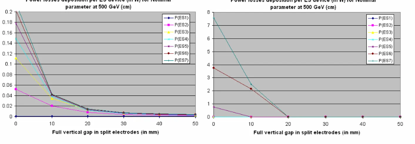
Results for different split electrodes
The power losses in the 7 ES devices have been computed for different sizes of the vertical gap in the electrodes (vertical gap = 10, 20, 30, 40, 50 mm). Figure 1 shows the power losses for each ES device as a function of the full vertical gap.
Figure 1 : Power losses for each 7 ES device for Nominal parameters (upper panel) and High Luminosity (lower panel) set at 500 GeV in the center-of-mass, induced by radiative Bhabha
processes (left panel) and beam particles (right panel).
Conclusions
In both Nominal and High Luminosity beam parameter sets, the power losses in the seven ES devices of the ILC alternative head-on scheme induced by the beam particles is always more than one order of magnitude greater than the power losses induced by the radiative Bhabha processes.
The level of the power losses induced by beam charge particles in the four last ES devices (3.5 kW for the very last one) shows that a full electrode design would not be realistic for High Luminosity beam parameters. Vertically split electrodes would most certainly be required in these cases.
An important question which remains to be investigated is whether losses up to 36 W distributed on the two Titanium split electrodes which are planned [1] are acceptable. Presumably, suitable collimators can be introduced between each of the 7 ES devices for protection.
Besides the beam distribution and the radiative Bhabha process, other sources from the beamstrahlung cone and from incoherent pairs are negligible in the ES.
References
[1] : “Technical challenges for head-on collisions and extraction line at the ILC”, O. Napoly & al. proceedings of PAC07 conference, Albuquerque, USA (EUROTeV-Report-2007-043).
[2] : http://flc-mdi.lal.in2p3.fr/spip.php?article27 [3] : http://flc.web.lal.in2p3.fr/mdi/BBSIM/bbsim.html