HAL Id: cea-02338541
https://hal-cea.archives-ouvertes.fr/cea-02338541
Submitted on 24 Feb 2020
HAL is a multi-disciplinary open access
archive for the deposit and dissemination of
sci-entific research documents, whether they are
pub-lished or not. The documents may come from
teaching and research institutions in France or
abroad, or from public or private research centers.
L’archive ouverte pluridisciplinaire HAL, est
destinée au dépôt et à la diffusion de documents
scientifiques de niveau recherche, publiés ou non,
émanant des établissements d’enseignement et de
recherche français ou étrangers, des laboratoires
publics ou privés.
C. Lejouad, B. Richard, P. Mongabure, S. Capdevielle, F. Ragueneau, S.
Kevorkian
To cite this version:
C. Lejouad, B. Richard, P. Mongabure, S. Capdevielle, F. Ragueneau, et al.. Effect of steel
reinforce-ment corrosion on the dynamic behavior of RC beams. FONTEVRAUD 9 - International Symposium:
Contribution of Materials Investigations and Operating Experience to Light Water NPPs’ Safety,
Per-formance and Reliability, Sep 2018, Avignon, France. �cea-02338541�
Effect of steel reinforcement corrosion on the dynamic behavior of
RC beams
Chaymaa LEJOUAD 1*, Benjamin RICHARD 1, Philippe MONGABURE 1, Sophie CAPDEVIELLE 2,
Frédéric RAGUENEAU 2, Sandrine KEVORKIAN 3
1 DEN-Service d’études mécaniques et thermiques (SEMT), CEA, Université Paris-Saclay, F-91191
Gif-sur-Yvette, France
2 LMT, ENS Paris-Saclay, CNRS, Université Paris-Saclay, 61 Avenue du Président Wilson, F-94235 Cachan,
France
3 Institut de Radioprotection et de Sûreté Nucléaire, 31 Avenue de la Division Leclerc, F-92260
Fontenay-aux-Roses, France
* E-mail: Chaymaa.Lejouad@cea.fr
Keywords: Reinforced concrete, corrosion, earthquake engineering, dynamic behavior
Abstract
Corrosion is one of the most common pathologies that affects reinforced concrete structures (RC). The fact that this phenomenon leads to a progressive loss of structural performance does not need further discussions. This loss of performance is a crucial issue for safety, especially when considering the coupling with an external loading such as an earthquake. The present study aims to quantify the time evolution of some quantities of interest, such as the eigenfrequencies, the modeshapes or the damping ratios, as functions of the corrosion degree. To reach this objective an extensive experi-mental campaign has been set up on simple but large-scale RC specimens. The consequences of the corrosion phenomenon on both the static and dynamic behaviors of beams are quantified, considering several steel configurations. In this paper, the experimental campaign is described. Especially, the accelerated corrosion method used is presented as well as the planned loading. The paper ends with a brief description of a simplified model which is under development. Due to its low computational demand, it will be able to be used within the framework of probability safety assessment (PSA) stud-ies.
1.
Introduction
Nowadays, reinforced concrete (RC) is one of the most widely used construction composite materials in the world. Due to the effects coming from the external environment along with time, specific pathol-ogies may appear. Among them, the steel reinforcement corrosion is one of the most preponderant pathologies which makes the structural performance decrease. This phenomenon can lead in its early stages to a loss of durability at the material scale, a loss of service ability and lately, a loss of structur-al safety. In other words, the corrosion phenomenon is responsible for a loss of performance structur-along with time.
For this reason and with the aim of predicting the time evolution of safety functions, the study of the influence of corrosion on the structural behavior of RC structures is of crucial importance. This state-ment is particularly true for vital facilities, such as nuclear power plants or dams.
As far as the structural behavior of RC elements is concerned, the corrosion leads to a decrease of the bearing capacity as well as a modification of the dynamic behavior. The aim of this study is to quantify the influence of corrosion on the quasi-static and the dynamic behavior of RC elements. In this paper, a brief state of the art will be presented. Then, the experimental campaign will be ex-posed as well as some perspectives related to the development of a numerical model with a low com-putational demand being able to describe the overall mechanical behavior of corroded RC structures.
2.
State of the art
Corrosion in reinforced concrete is caused by the introduction of specific aggressive agents from the external environment to the steel bar surface within the pores of concrete. In this context, we distin-guish two types of steel corrosion: a first type due to chloride penetration [1] and a second resulting from a carbon dioxide dissolution [2].
In the case of corrosion induced by carbonation, also called uniform corrosion, we observe a uniform distribution of the cross section loss along the steel bar. Whereas, in corrosion induced by chloride, also called pitting corrosion, the morphology of corroded bars exhibits a localized loss of cross section. As a result, this second type of corrosion seems to be the most penalizing for RC structures.
According to the aforementioned reasons, the focus will be on corrosion induced by chlorides. As a matter of fact, corrosion in RC is a long process: a study carried out on a RC specimen subjected to natural corrosion shows that after 16 months of exposure, the degradation of the specimen remains insignificant [3].
In the research field, using natural corrosion process to get corroded specimens is highly time-demanding. Thus, scientists have come up with technics to accelerate corrosion namely galvanostatic method (whether by imposed current [4] or imposed voltage[5]), artificial environment [6] [7] and addi-tives in concrete mixture [8] [9].
The main chemical reaction responsible for corrosion is the oxidation of steel (Equation 1) or in other words the exchange of negative charges (electrons) between the steel element and another element such as oxygen (Equation 2). So, the corrosion phenomenon is fully driven by electrons flow or, in other words, by the electrical current. From a chemical point of view, the accelerated corrosion by imposed current method seems to be the closest to natural corrosion.
𝐹𝑒 → 𝐹𝑒
2++ 2𝑒 −
2𝐻2𝑂 + 𝑂2+ 2𝐹𝑒 → 2𝐹𝑒2++ 4𝑂𝐻−
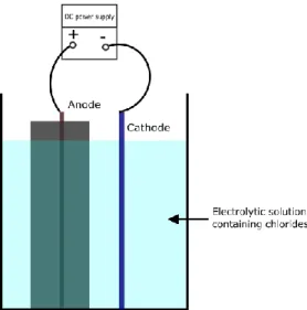
The accelerated corrosion method with imposed current consists in applying an electrical current from a DC power supply* between the cathode (which can be made from stainless steel [10], copper [11] or platinum [12]) and the anode which is the reinforcement inside de RC specimen. The whole specimen should be immersed in an electrolytic solution to guarantee electrical conduction (Figure 1) : the com-position of the solution can vary according to authors but generally contains 3 to 5% of NaCl [6] [12].
Figure 1: Set-up for accelerated corrosion by imposed current
Since the accelerated corrosion by imposed current method is an electrical process, some empirical equations exist to describe this phenomenon. The most used one is Faraday’s law (Equation 3) [5].
∆𝑤 =
𝑀.𝐼.∆𝑡𝑧.𝐹 (*) Device delivering direct current (DC)
Equation 1 Equation 2
Where ∆𝑤 is the mass of steel consumed due to corrosion (kg/m²), 𝐼 is the current density (A/m²), Δt is the exposure time (s), 𝐹 is the Faraday constant 96 500 (A/s), 𝑧 is the ionic charge (2 for Fe), 𝑀 is the atomic weight of metal (g/mol).
The Faraday’s law is suitable for the corrosion of a bare bar due to the presence of chlorides at the steel bar surface since the beginning of the corrosion process. Whereas, in RC chlorides need to reach the steel bar surface from the electrolytic solution within concrete pores; that is to say that cor-rosion does not start immediately and the applied current initially is used to depassivate the steel rein-forcement by spreading chlorides into the concrete matrix. To take into account this aspect, a coeffi-cient λ between 1.3 and 2, is added to the basic Faraday relationship [13] (Equation 4).
∆𝑡 =
𝜆. Δ𝑤. 𝑧. 𝐹
𝑀. 𝐼
As far as the set current density is concerned, many studies have shown that the choice of the current density value has a direct consequence on the more or less similitude with natural corrosion regarding crack patterns for example. The majority of studies suggests not to exceed 100 µA/cm² to have similar structural effects as natural corrosion [14] [15].
This type of corrosion leads to a reduction of the resistant section and reinforcement ductility (Figure 2), concrete spalling and bond strength degradation due to high stresses resulting from the formation of corrosion products (Figure 3). All these consequences lead to a decrease of the bearing capacity [16] and ductility offer.
Figure 2: Evolution of corroded steel bars ductility [16]
Figure 3: Crack patterns due to corrosion [17]
Regarding the dynamic behavior of corroded RC elements, to our knowledge no study has been done on this subject. However, some cyclic loads applied on corroded specimens show a decrease of hys-teretic capacity and dissipation energy [18] [19] .Therefore, the dynamic behavior might be modified.
3.
Experimental campaign: DYSBAC
The name of this experimental campaign, DYSBAC, is a French acronym for “Dynamic behavior of corroded RC structure”. This campaign will be performed by means of the AZALEE shaking table and the strong floor, as part of the TAMARIS experimental facility operated by the French Alternative En-ergies and Atomic Energy Commission (CEA). The main objective of this campaign is the study of the influence of corrosion on:
The quasi-static behavior (bearing capacity, energy dissipation, hysteretic capacity…)
The dynamic behavior (natural frequencies, solicitation amplification, mode shapes…) Equation 4
3.1. Samples
For the sake of simplicity and representativeness of a real structure, the choice of RC beams has been made. Considering some design constraints related to test facilities such as the size of the strong floor (4.5 m length) , the maximal stroke of the available actuator (± 400 mm) and operating frequency range of AZALEE shaking table (0 - 30 Hz); we come up with the geometry of DYSBAC specimens shown in (Figure 4.a).
The reinforcement was designed according to the BAEL which is a French standard used before the Eurocodes to design RC structures. The Figure 4.b shows the details of the considered reinforcement.
(a) The geometry of the specimen (b) Reinforcement details Figure 4: Geometry and reinforcement details of the specimens - dimensions in centimeters
Regarding materials, the considered concrete has a compressive strength measured on cubes equal to 30 MPa with a water cement ratio around 0.6 representative of concrete in aged RC structures. The steel is a B500A steel with an average yield strength equal to 500 MPa and an ultimate strain (Agt) equal to 2.5%.
In order to define an experimental corrosion methodology, some preliminary experiments were con-ducted:
On a bare bar (Figure 5.a)
On a bare reinforcing cage (Figure 5.b)
(a) for a bare bar (b) for a bare reinforcing cage Figure 5: Accelerated corrosion set-up
These experiments showed that it is difficult to control corrosion in the case of a reinforcing cage be-cause of the heterogeneous current distribution on the different parts of the reinforcing cage.
As a result, three types of specimens were considered:
Beam
𝐶
1 with longitudinal bars corrosion: an insulation is put on stirrups Beam
𝐶
2 with transverse reinforcement corrosion: an insulation is put on longitudinal bars Beam𝐶
3 with both transverse and longitudinal reinforcement corrosion : no insulation is put The insulation consists of putting an electrically insulating painting and a heat-shrinkable covering. Electrical connection is achieved by drilling the bar and welding an electrical wire.To ensure the good behavior of the insulation and of the electrical connection, an experiment was achieved on a steel reinforcing cage with insulation (Figure 6.a). At the end of the experiment, only longitudinal bars were corroded (Figure 6.b); the effectiveness of insulation is therefore confirmed.
(a) At the beginning of the experiment (b) At the end of the experiment Figure 6 : Accelerated corrosion performed on a reinforcing cage with insulation
3.2. Samples corrosion
Before corroding the DYSBAC specimens, three small-scale beams with the three reinforcing configu-rations (𝐶1,𝐶2 and 𝐶3) were subjected to an accelerated corrosion by imposed current (Figure 7). At the end of this experiment, crack patterns on each beam type (Figure 8) reveal the corroded reinforcement part. Therefore, the corrosion set-up was precisely defined for each beam type.
(a) 𝑪𝟏configuration (b) 𝑪𝟐configuration (c) 𝑪𝟑 configuration Figure 7 : Accelerated corrosion performed on small-scale specimens
(a) 𝑪𝟏 configuration (b) 𝑪𝟐 configuration (c) 𝑪𝟑 configuration Figure 8: Crack patterns observed at the end of the accelerated corrosion process
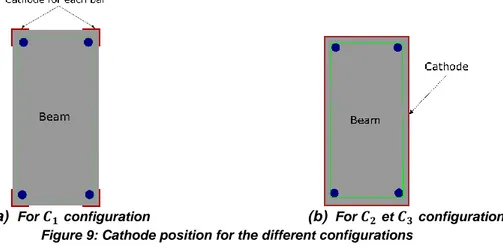
For the 𝐶1beam configuration :
Every longitudinal bar is considered as an anode with an independent cathode in stainless steel (Figure 9.a)
A four channels DC power supply is considered For both beam configurations 𝐶2 and 𝐶3:
The full beam will be wrapped with the stainless steel grid (Figure 9.b) One DC power supply is considered
(a) For 𝑪𝟏configuration (b) For 𝑪𝟐et 𝑪𝟑configurations Figure 9: Cathode position for the different configurations
For all beams, a current density of 100 µA/cm² is considered [20] to achieve three target mass losses of 5% (believed to be the threshold of the bond loss between steel and concrete [21]), 10% (rate from which civil engineering maintenance operations begin[22]) and 15% (believed to be the threshold from which a change of failure mode is observed [23]).
All the beams are immerged in a 3.5% NaCl solution (Figure 10). The exposure duration is estimated for each type of beam and each corrosion rate using Faraday‘s law (Equation 4) with λ = 1.3.
Table 1 summarizes the applied current values and the estimated exposure time for each corrosion rate.
Configuration 𝐶1 Configuration 𝐶2 Configuration 𝐶3
For each bar HA12 44 stirrups HA8 4 bars HA12 and 44 stirrups HA8 Corrosion rate (%) Exposure dura-tion (days) Corrosion rate (%) Exposure dura-tion (days) Corrosion rate (%) Exposure dura-tion (days) 5% 47 5% 31 5% 36 10% 94 10% 62 10% 72 15% 141 15% 94 15% 109
Table 1 : Exposure duration for different beams configuration
3.3. Sample testing
The setup is similar to the one used for the IDEFIX campaign [24].The beams will be excited along their weakest flexural axis; the boundary conditions consist of:
Blade-shaped supports allowing the rotation at the beam extremities,
Two air-cushion systems to bear the beam weight and to reduce drastically the friction be-tween the beam and the shaking table’s or strong floor’s upper plate.
3.3.1. Quasi-static loading
A classical four points bending test is performed on the TAMARIS strong floor (Figure 11.a). Indeed, this test is operated by an actuator linked with a metal beam able through swivels at its ends to dis-tribute the loading on two points of the DYSBAC beam. Specific machine elements have been de-signed (Figure 11.b).
(a) General view on the experimental setup on the
strong floor (b) Designed setup for 4 points bending test Figure 11: Quasi-static testing
The applied loading includes blocks of 5 identical cycles of prescribed displacement, with an amplitude increase of 2 cm between two consecutive blocks. The aim of the 5 cycles is to stabilize the new level of damage of the current block. One cycle includes 4 phases which are: loading in one direction, un-loading, loading in the other direction and unloading (Figure 12).
Figure 12: Planned load in quasi-static testing
The same loading will be applied on 10 specimens: a non-corroded beam in addition to 3 beams of each reinforcement configuration and each corrosion rate. The end of the test may coincide with the beam failure or the actuator maximal stroke especially for the non-corroded beam.
The deformed shape of the beam in 4 points bending is close to the first mode shape. Therefore, it’s possible to assess the evolution of the hysteretic energy dissipation within cycles.
Moreover, every specimen will be subjected on the strong floor to hammer tests in different boundary conditions: free-free and bi-supported; and even between blocks to evaluate the change of modal characteristics as a function of damage.
3.3.2. Dynamic loading
The dynamic test will be performed on AZALEE shaking table. It’s a 6 x 6 m² shaking table able to reproduce seismic signals up to 1.5 g. The table is controlled on 6 degrees of freedom (3 rotations, 3 translations) (Figure 13).
Figure 13: General view of the experimental setup for dynamic tests
Before applying the dynamic loads, a modal characterization will be performed on the 10 DYSBAC beams intended to be tested on AZALEE shaking table. This characterization consists of hammer tests in addition to a white noise signal (PGA = 0.1 g).
The dynamic loading consists in a synthetic signal able to excite only the first natural mode. This sig-nal might be different for each beam configuration and each corrosion rate so it is designed after the modal characterization of each beam. Increasing levels of the signal are tested.
1st block
The applied signals are generated using the inverse Fast Fourier Transformation (FFT) from a defined spectrum. In order to anticipate the modal frequency drop due to damage, a crenel spectrum is con-sidered with nominal acceleration between 0.5 times and 1.05 times the first natural frequency and equal to zero outside (Figure 14). This choice anticipates the modal frequency drop due to damage and allows to constantly exciting the sought modal frequency all along the test.
Figure 14: Crenel spectrum used in signal generation
It is to be noted that digital image correlation technique will be used for quasi-static and dynamic tests. Indeed, it consists of a painted strip on the upper surface of the beam. The displacement of this strip will be followed in time using a stereoscopic system.
3.3.3. Further experiments
After dynamic and quasi-static tests, some corroded specimens will be subjected to post-mortem analysis in order to measure the actual mass loss due to corrosion and to observe a 3D profile of cor-roded bars at different corrosion rates.
In addition to the DYSBAC beams, some special specimens were designed and manufactured:
- Pull-out specimens (Figure 15.a), the objective of having such specimens is to evaluate the bond between concrete and steel at different corrosion rates.
- Prismatic concrete specimens of 72 x 72 mm² cross section and 4.5 m length crossed by a longitudinal bar HA12 (Figure 15.b). These specimens are intended to be corroded using the imposed current accelerated technique. At the end of corrosion process, the bar is supposed to be cleaned using ASTM standards [25] then scanned using a laser profilometer. It will be useful to provide numerical models with a 3D profile of the bar at different corrosion rates.
(a) Pull-out specimens (b) Prismatic specimens intended to be corroded Figure 15: Complementary specimens
4.
Perspectives
DYSBAC experimental campaign (not executed yet) will improve the state of the art concerning dy-namic behavior of RC structures. Actually, by means of applying either quasi-static or dydy-namic loading on large-scale beams, the quantification of some quantities of interest, such as the eigenfrequencies, the modeshapes or the damping ratios will be possible.
So as to capitalize these results coming from the experimental campaign, a numerical model is devel-oped. The considered model relies on the Timoshenko multi-fiber element (Figure 16) [26].
Figure 16: Principle of multi-fiber beam [26]
The numerical model should take into account the distribution of the section loss due to corrosion along the longitudinal bars. It should also be able to reproduce the effect of the bars swelling due to the formation of corrosion products as well as the bar sliding due to the loss of bond between steel and concrete.
At the time this paper has been written, first experimental tests are to be performed soon and the nu-merical model is still under development.
Acknowledgements
The French Institute for Radioprotection and Nuclear Safety (IRSN) and the Nuclear Energy Division of the French Sustainable Energies and Atomic Energy Commission (CEA/DEN) are kindly thanked for financial supports. The research reported in this paper has been supported in part by the SEISM Paris Saclay Research Institute.
References
[1] E. Ghali, « Électrochimie, corrosion et protection ».
[2] F. Lea, « The Chemistry of Cement and Concrete, Chemical Publ. Comp », Inc., New York, 1972. [3] Mohammed Maslehuddin, Ibrahim A. Allam, Ghazi J. Al-Sulaimani, Abdulaziz Al-Mana, and Sahl N.
Ab-duljauwad, « Effect of Rusting of Reinforcing Steel on its Mechanical Properties and Bond with Concrete », Materials Journal, 1990.
[4] F. Paradis, « Influence de la fissuration du béton sur la corrosion des armatures : caractérisation des pro-duits de corrosion formés dans le béton », Université Laval, 2009.
[5] S. Altoubat, M. Maalej, and F. U. A. Shaikh, « Laboratory Simulation of Corrosion Damage in Reinforced Concrete », Int. J. Concr. Struct. Mater. vol. 10, no 3, p. 383‑391, sept. 2016.
[6] Y. Yuan, Y. Ji, and S. P. Shah, « Comparison of two accelerated corrosion techniques for concrete struc-tures », ACI Struct. J., vol. 104, no 3, p. 344, 2007.
[7] « Comparison of Two Accelerated Corrosion Techniques for Concrete Structures », ACI Struct. J., vol. 104, no 3, 2007.
[8] J. Xu, L. Jiang, W. Wang, et Y. Jiang, « Influence of CaCl2 and NaCl from different sources on chloride threshold value for the corrosion of steel reinforcement in concrete », Constr. Build. Mater. vol. 25, no 2, p.
663‑669, févr. 2011.
[9] « Long-Term Performance of Corrosion-Damaged Reinforced Concrete Beams », ACI Struct. J., vol. 102, no
5, 2005.
[10] A. K. Azad, S. Ahmad, and S. A. Azher, « Residual strength of corrosion-damaged reinforced concrete beams », Mater. J., vol. 104, no 1, p. 40–47, 2007.
[11] Y.-C. Ou et N. D. Nguyen, « Influences of location of reinforcement corrosion on seismic performance of corroded reinforced concrete beams », Eng. Struct., vol. 126, p. 210‑223, nov. 2016.
[12] O. Loukil et al., « Experimental study of corrosion-induced degradation of reinforced concrete elements », in International RILEM Conference on Materials, Systems and Structures in Civil Engineering Conference seg-ment on Electrochemistry in Civil Engineering, 2016.
[13] S. Imperatore, Z. Rinaldi, et C. Drago, « Degradation relationships for the mechanical properties of corroded steel rebars », Constr. Build. Mater. vol. 148, p. 219‑230, sept. 2017.
[14] C. Andrade, C. Alonso, and F. J. Molina, « Cover cracking as a function of bar corrosion: Part I-Experimental test », Mater. Struct. vol. 26, no 8, p. 453‑464, oct. 1993.
[15] T. A. El Maaddawy et K. A. Soudki, « Effectiveness of impressed current technique to simulate corrosion of steel reinforcement in concrete », J. Mater. Civ. Eng., vol. 15, no 1, p. 41–47, 2003.
[16] A. A. Almusallam, « Effect of degree of corrosion on the properties of reinforcing steel bars », Constr. Build. Mater. vol. 15, no 8, p. 361‑368, déc. 2001.
[17] W. Zhu et R. François, « Corrosion of the reinforcement and its influence on the residual structural perfor-mance of a 26-year-old corroded RC beam », Constr. Build. Mater. vol. 51, p. 461‑472, janv. 2014. [18] Y. Ma, Y. Che, et J. Gong, « Behavior of corrosion damaged circular reinforced concrete columns under
cyclic loading », Constr. Build. Mater. vol. 29, p. 548‑556, avr. 2012.
[19] A. Guo, H. Li, X. Ba, X. Guan, et H. Li, « Experimental investigation on the cyclic performance of reinforced concrete piers with chloride-induced corrosion in marine environment », Eng. Struct., vol. 105, p. 1‑11, déc. 2015.
[20] S. Caré and A. Raharinaivo, « Influence of impressed current on the initiation of damage in reinforced mortar due to corrosion of embedded steel », Cem. Concr. Res., vol. 37, no 12, p. 1598‑1612, déc. 2007.
[21] Y. Auyeung, « Bond properties of corroded reinforcement with and without confinement. », 2002.
[22] « Projet APPLET : Durée de vie des ouvrages en béton : Approches prédictives performantielles et probabi-listes », 2006.
[23] A. Ouglova, « Etude du comportement mécanique des structures en béton armé atteintes par la corrosion », PhD Thesis, Cachan, Ecole normale supérieure, 2004.
[24] T. Heitz, A. Le Maoult, B. Richard, C. Giry, and F. Ragueneau, « Dissipations in reinforced concrete compo-nents: Static and dynamic experimental identification strategy », Eng. Struct., vol. 163, p. 436‑451, mai 2018.
[25] A. G1-03, « Standard practice for preparing, cleaning, and evaluating corrosion test specimens », Annu. Book ASTM Stand., 2003.
[26] S. Capdevielle, « Introduction du gauchissement dans les éléments finis multifibres pour la modélisation non linéaire des structures en béton armé, PhD thesis », Université Grenoble Alpes, 2016.
[27] I. Bitar, N. Benkemoun, P. Kotronis, et S. Grange, « A novel multi-fiber Timoshenko beam finite element formulation with embedded discontinuities to describe reinforced concrete failure under static loadings », 2016.
![Figure 2: Evolution of corroded steel bars ductility [16]](https://thumb-eu.123doks.com/thumbv2/123doknet/12911185.372465/4.892.115.786.581.818/figure-evolution-corroded-steel-bars-ductility.webp)


![Figure 16: Principle of multi-fiber beam [26]](https://thumb-eu.123doks.com/thumbv2/123doknet/12911185.372465/11.892.252.641.325.434/figure-principle-of-multi-fiber-beam.webp)
