HAL Id: hal-00712127
https://hal.inria.fr/hal-00712127
Submitted on 26 Jun 2012
HAL is a multi-disciplinary open access
archive for the deposit and dissemination of
sci-entific research documents, whether they are
pub-lished or not. The documents may come from
teaching and research institutions in France or
abroad, or from public or private research centers.
L’archive ouverte pluridisciplinaire HAL, est
destinée au dépôt et à la diffusion de documents
scientifiques de niveau recherche, publiés ou non,
émanant des établissements d’enseignement et de
recherche français ou étrangers, des laboratoires
publics ou privés.
Co-Designed Cache Coherency Architecture for
Embedded Multicore Systems
Jussara Marandola, Loïc Cudennec
To cite this version:
Jussara Marandola, Loïc Cudennec. Co-Designed Cache Coherency Architecture for Embedded
Mul-ticore Systems. IP-Embedded System Conference and Exhibition, Dec 2011, Grenoble, France.
�hal-00712127�
Abstract:
One of the key challenges in chip multi-processing is to provide a programming model that manages cache coherency in a transparent and efficient way. A large number of applications designed for embedded systems are known to read and write data following memory access patterns. Memory access patterns can be used to optimize cache consistency by prefetching data and reducing the number of memory transactions. In this paper, we present the round-robin method applied to baseline coherency protocol and initial analysis of one hybrid protocol that performs speculative requests when access patterns are detected. We also propose to manage patterns through a dedicated hardware component attached to each core of the processor.
1. INTRODUCTION
The cache coherence mechanisms are a key component towards achieving the goal of continuing exponential performance growth through widespread thread-level parallelism [1].
The thread level parallelism (TLP) has turned attention of mainstream microprocessors vendors by designing chips with multiple processors, called multicore or chip multiprocessors (CMPs). Today, the main memory in multicore era presents
Higher demands: bandwidth and capacity [2]. Chip multi-processing has become very popular these past years with the possibility to offer the power of massively parallel architectures in a single chip. One of the key challenges arising from chip multi-processing consists in designing the right programming model while relying, as few as possible, on the underlying hardware. This is particularly critical in the field of data management between many-core caches. In this architecture, each core may store a copy of the data in its cache. Cache coherence is either directly managed by the user or falls under the control of a cache coherence unit. This second solution makes all updates and data transfers transparent for the user. It also simplifies the development of applications.
Unfortunately, it is known to have a cost in term of hardware design, refraining from being massively adopted in embedded computing. In order to make data coherence more attractive for massively-parallel embedded architectures, we think that cache Coherence models and protocols should be tightly adapted to suit the targeted applications needs. A large number of applications used to be deployed on embedded devices are based on image, video, data stream and workflow processing.
This class of applications tends to access data using a given set of memory access patterns. These patterns can be used to optimize the cache coherence protocol, by prefetching data and reducing the number of memory transactions. In this paper we propose a hardware extension that is able to store patterns, with first approach that we focused on cache hierarchy model and method of cache coherency protocol based on hardware behavior. The details about memory addresses recognition that
Are part of pattern are not described in this paper. Other contribution is regarding about the study of state of the art in cache coherency protocols. The remainder of this paper is organized as follows. Section II explains the advantages of Hybrid Protocol comparing several cache policies of protocols. Section III presents the brief state of art about CMP architecture and baseline protocol. Section IV gives an overview of co-designed cache coherency architecture. Section V describes the flow of read transaction of hybrid protocol and the round-robin method. Finally, section VI concludes and gives some perspectives on this work.
II. RELATED WORKS OF CACHE POLICIES
The optimization of cache coherency traffic of Cache Coherency Architecture is specialized for applications based on memory access patterns and our contribution is concerning the treatment of memory access patterns. This treatment of memory access patterns were specified through hardware/software co-design. A new hardware-component and the new cache coherency protocol
IP-ESC’11
CO-DESIGNED CACHE COHERENCY ARCHITECTURE FOR EMBEDDED
MULTICORE SYSTEMS
Jussara Marandola, USP (São Paulo, Brazil)
Loic Cudennec, CEA-LIST (Saclay, France)
that implement the speculation of messages by memory access patterns. The hybrid protocol is a cache coherency protocol based on baseline protocol and speculative protocol. Our first objectives were provide the best cache politics to solve the problem of cache lookup and transaction messages model in the system of cache for our cache coherency protocol. Actually, the architectures more advanced present many levels of hierarchy memory and new concept of 3D memory. The main different between Cache Coherency Architecture and others architectures is your Hardware-component to store the address in form of table patterns.
In the state of the art, our protocol is based on proximity aware protocol model [3], especially on concept of home node and alternative home node protocol [4], to implement our interleaved messages in the system. The mechanisms of pattern lookup could be compared with conterminous group and locality [5]. Additionally, we analyzed several cache politics such as Spatio-Temporal Memory Streaming (STeMS) [6], Spatial Memory Streaming (SMS) [7] and Temporal Streaming of Shared Memory (TMS) [8]. In the table below, we show The characteristics of comparison between cache policies:
Table 1: Cache Policies III. CMP ARCHITECTURE
Shared Memory Chip Multi-Processor Architectures are now expected to host up to hundreds of cores. These cores are connected through a scalable network based on a mesh topology. Communications are established between neighbors, In the same way than ad-hoc networks. In this context, data coherence occurs when a data is replicated on different caches, due to concurrent read and write operations. Versions of the data may differ between cores and main memory. In order to maintain consistency, one popular approach resides in the use of a four-state, directory-based cache coherence protocol.
This protocol, called baseline protocol, is a derivative protocol of the Lazy Release Consistency [9] protocol, as found in some Distributed Shared Memory systems. This section we described the processor architecture that we use for our study. We also described the baseline coherence protocol, an updated MESI protocol for directory-based coherence architecture.
A. Baseline Architecture
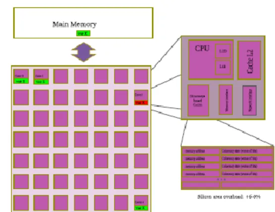
Figure 1: CMP Architecture Multicore based on baseline protocol
The architecture is a chip multiprocessor consisting of 64 cores arranged as 8 x 8 mesh of tiles. Each tile contains an in-order with private L1 instruction and data caches, distributed shared memory L2 instruction and data cache, a directory controller, and a network switch, as show in figure 1. The main feature described in our co-designed cache
Coherency architecture is regarding the cache design with data consistency between level 2 distributed shared caches. It differs of Baseline Architecture standard [3] because all level 2 caches are private.
This shows a figure 1 consisting of CMP architecture of general purpose. The directory-based cache size is matching cache size. However, the data is not equivalent. While cache tends to store the data with high spatial locality, in the directory addresses are not consecutive (to avoid hotspots in the communication network).
In order to illustrate the baseline protocol behavior, we consider a 64-cores CMP machine as shown in Figure 1. Each core of the machine hosts a L1 instructions and data cache, a L2 cache, a directory-based cache, a memory interface and a network interface. The directory-based cache hosts coherence information for a given set of data stored in the cache. Sorted by memory address, the coherence information is (N + 2) bits long, with N the number of cores in the system. Traditionally, the coherence information is composed by 2 bits representing the coherence state, plus an N bits-long presence vector. The coherence state field represents four states, as defined by the MESI protocol:
M (modified): a single valid copy exists across the whole system, the core owning this copy is named the Owner of the data and has the right to write. The value of this copy has changed since the data was cached by the owning core.
E (exclusive): a single valid copy exists across the whole system; the core owning this copy is named the Owner of the data and has the right to write. The data was not modified since it was cached by the owning core.
S (shared): multiple copy of the data exist, all copy are in read-only mode. Any core with a copy of the data is named a Sharer.
I (invalid): this copy is currently invalid and should not be used for other purpose than to be discarded.
The length of the presence vector is equal to the number of cores in the system. Where a 0 at the ith
bit means the data is not cached in the core i, and a 1 at the jth bit means the data is cached in the core j.
For each data managed by the consistency protocol, a dedicated node, named home-node, is in charge of managing coherence information for this particular data. In the literature, many cache coherence protocols, such as proximity-aware [3], alternative home node [4], MESI [10] and MESIF [11] derivate from the baseline protocol.
B. Baseline Protocol
The problem observed on time request to memory access when the data is not found in l2 cache. The cost performance is very high then the baseline protocol provides the method of home node management. For conventional directory-based coherence, a read or write miss to a line that is in the shared or uncached state always results in home node searching the data. However, if the data may not be in home node l2’s and accesses to off-chip memory is very expensive.
Baseline protocol consider the cache lookup standard and send the request data to home node. In case of cache miss, the home node forward request to closest sharer. The data are shared with requester after the message ACK is sent to home node. In this way, all requests are sent to home node, providing the hotspot of messages.
IV. CACHE COHERENCY ARCHITECTURE
The Cache Coherency Architecture has 64 cores, in our example for general purpose, where each CPU core of the system may be involved in the exchange of coherence messages with FOUR different roles. The exact roles play by a core is data centric, i.e. a core can plays one (or several) roles in transaction related to a given data, and assume different roles considering different data.
Requester, the core asks for a data.
Home node, the core is in charge of keeping track of the coherence information of a requested data in the system.
Sharer, the core has currently a copy of the data in its cache. This copy is in ’shared mode’, i.e. multiple copies of the data can exist at the same time in different caches of the system.
Owner, the core has currently a copy of the data in its cache. This copy is in ’Exclusive’ or ’Modified’ mode, i.e. only one and only one instance of this data can exist at this given time across the whole system.
Each CPU has the following components of hierarchy cache system: cache l1, cache l2 (shared inclusive), directory of cache coherence and ’Pattern Table’. This pattern table has the important functions: to manage the pattern table (PT’s) on each core of the system and to modify a regular data consistency.
Considering this hierarchy memory, we could describe the behavior of hardware through the following pseudo code:
Pseudo code of Hardware Behavior
1. CPU Core process a load instruction
For data of @x
- L1/L2 cache look-up for @x If cache hit:
- retrieve the data from cache and complete the load instruction END
else /* this is a cache miss */ Pattern table look-up
if pattern table hit
cocca_home=get_home_node_RR_page(@ x)
send RD_RQ_SPEC(pattern_@x) to cocca_home
END @x process
else /* this is a pattern table miss */ Baseline_home= get_home_node_RR_line(@x) send RD_RQ(@x) to baseline_home END @x process
Co-Designed Cache Coherence Architecture relys on memory access patterns. The hardware-component manages the pattern table on each core of the system and modifies the regular data consistency protocol to benefit from pattern tables. The highlights of this hardware approach are concerning the reduction of the messages transaction and optimization of cache consistency protocol oriented by pattern table.
Actually, the new multi-core architectures such as MD K10 and Intel Nehalem have the hierarchy memory composed by 3 levels (l1/l2/l3). The AMD Athlon 64 microarchitecture has four caches specialized: cache l1 instruction, cache l1
associated to TLB and cache l1 of data. Cache Coherence Architecture presents the simple cache based on direct mapping to reduce the silicium cost and complexity of hardware design.
A. Pattern Table
Figure 2: Pattern Table is a hardware-component auxiliary of cache coherency and oriented by patterns management. This pattern table is similar to a hash table or a cache. The address to check is compared with a sub-set of slots witch could possible stores this address. The number of slots composing this sub-set is called associativity.
Patterns are used to summarize the spatial locality associated to the access of a data (or in a more general way to a trigger). In the current design of patterns are considered as triplet’s equation:
Pattern = [baseaddress, length, stride] (1) Where base address is the address of the first cache line of the pattern, length, expressed the number of cache lines belonging to the pattern, and stride expresses the distance between two consecutive cache lines of the pattern. In the figure 2, we presented some initial concepts about Pattern Table. Considering a core with a cache miss for a variable of address ’@11’, the Pattern Table is searched for a trigger matching ’@11’. In case of matching, the Pattern Table returns a Pattern Hit signal as well as the pattern description. In this case the pattern description is @11, 3, 2, which means that
’@11’ is the base address of a pattern of 3 cache lines with a stride of 2 cache lines. If we consider architecture with cache lines of 128 Byte and pages size of 4096 Byte, thus a page contains 32 cache lines.
B. Method Round-Robin
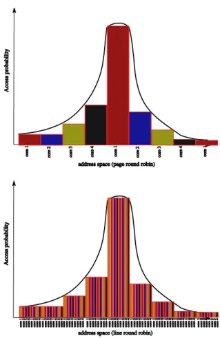
The key innovation in this cache coherency architecture is based on Method of Round-Robin to determine the home node of data. When a processor needs a data it first needs to check with the home node of this data what is the coherency state. This task is handled by the coherence engine which send/received all messages related to shared memory access.
Figure 3: Probability of memory access to home node regarding addresses accessed. These graphs show the distribution round-robin by page and line. The hotspot is demonstrated by round-robin by page memory.
Therefore, the initial step for the coherence engine is to determine which core in the system is the Home node of the requested data. The basic, and classical, algorithm perform a modulo operation on the low order bits of the address of the data to determine the home node. This algorithm has many advantages: it is simple, fast and, considering an even distribution of shared memory accesses, by dispatching requests among all cores it provides good bandwidth utilization. The follow equation describes the function regarding the type of
granularity:
HNid = (dataaddressincacheline)(Nb.cores) (2)
One key question is the granularity used for the round robin algorithm. For instance it has be shown that memory access are not distributed in homogeneous way leading to an uneven bandwidth consumption (some cores are hot stop).
V. HYBRID PROTOCOL
The basic idea in the Hybrid coherence protocol is to support two different kinds of Home Node.
According on previously extracted patterns (pattern extraction is out of the scope of this paper), coherence actions are taken either at the cache line granularity or at the pattern granularity. Therefore these structural information allow anticipating and modifying onthe-fly the granularity of the coherence messages. This trick relies on the storage of this structural information related to the application behavior for every core within a dedicated pattern table and an additional stage (a level of indirection) is introduced in the protocol. Through pattern table we could define the granularity of messages in the cache coherence protocol conforming demonstrated at figure yet. The main goal is provide the hybrid way to play two kinds of messages regarding pattern miss or pattern hit.
To represent home node function when we observed the miss pattern table, we demonstrated the algorithm round-robin that implements partial behavior of hybrid protocol to choice of home node. #include <stdio.h> #include <stdlib.h> #define NB_CORE_IN_THE_SYSTEM 64 #define PAGE_SIZE 4096 #define LINE_SIZE 128 #define ROUNDROBIN_PAGE_GRANULARITY 1 #define ROUNDROBIN_LINE_GRANULARITY 2
/* This function returns the home node corresponding to an address */ int get_home_id (void* an_address, int nb_core_in_the_system, int HN_POLICY) { int home_node_id; switch (HN_POLICY) { case ROUNDROBIN_LINE_GRANULARITY: home_node_id = ((long) an_address / LINE_SIZE % nb_core_in_the_system); break;
case
ROUNDROBIN_PAGE_GRANULARITY : home_node_id = ((long) an_address / PAGE_SIZE % nb_core_in_the_system); break;
default: /* centralized home node */ home_node_id = 0;
break;
}return home_node_id; }
Table 2: Home Node Function Code Description This program computes the home node id for every elements of a NxM matrix
Please enter the (N) height of the matrix: -->4
Please enter the (M) width of the matrix: -->4
Please select the home node allocation policy: Default behavior is centralized coherency (home node always set to 0)
Otherwise, please select: 1) Page granularity. 2) Line granularity. -->1
Policy set to page round robin
Matrix to allocate is 4X4
my_matrice[0][0] address 0xc3c010 value 0.50 home node 60
my_matrice[0][1] address 0xc3c018 value 1.50 home node 60
my_matrice[0][2] address 0xc3c020 value 2.50 home node 60
my_matrice[0][3] address 0xc3c028 value 3.50 home node 60
my_matrice[1][0] address 0xc3c030 value 4.50 home node 60
my_matrice[1][1] address 0xc3c038 value 5.50 home node 60
my_matrice[1][2] address 0xc3c040 value 6.50 home node 60
my_matrice[1][3] address 0xc3c048 value 7.50 home node 60
my_matrice[2][0] address 0xc3c050 value 8.50 home node 60
my_matrice[2][1] address 0xc3c058 value 9.50 home node 60
my_matrice[2][2] address 0xc3c060 value 10.50 home node 60
my_matrice[2][3] address 0xc3c068 value 11.50 home node 60
my_matrice[3][0] address 0xc3c070 value 12.50 home node 60
my_matrice[3][1] address 0xc3c078 value 13.50 home node 60
my_matrice[3][2] address 0xc3c080 value 14.50 home node 60
my_matrice[3][3] address 0xc3c088 value 15.50 home node 60
Table 3: Execution program of addresses memory A. Performance Model
The performance model evaluates the cost of performance based on our Co-Designed Cache Coherence Architecture.
Inittialy, the performance model has the following parameters:
L2 Lookup: cost of cache lookup L2;
DirLookup: cost of directory of cache coherence lookup;
PTLookup: cost of pattern table lookup;
Mem: cost of memory access;
msg: cost of message transfer between cores in the
system.
Figure 4: Cost Coherence Performance
VI. CONCLUSION
With the growing scale of chip multi-processors, data cache consistency becomes one of the key challenge to efficiently support parallel applications. This is particularly true in the context of embedded systems. A large number of embedded applications read and write data, according to memory access patterns. These patterns can be used to optimize cache coherence protocols and therefore, to improve application performances when sharing data among cores. In according our state of art, our hybrid protocol provides the advantages about home node policy because he adopts the hybrid policy based on messages standard and messages speculatives. Our cache coherence architecture differs the others architectures regarding some propreties as NUCA cache and new component hardware oriented by pattern memory access. We concluded that our cache coherence architecture is based on CMP architecture, directory-based cache and lazy realese consistency model.
The CMP architecture is inspired at Baseline architecture, but the different is concerning the L2 shared cache. Our hybrid protocol implements the round-robin method that provides the two roles in the memory systems: baseline home node and pattern home node. This method optimize the
memory access providing the speculation of pattern messages. In the performance model we concluded that our hybrid protocol is more efficiency than baseline protocol when applied the formula with pattern table.
ACKNOWLEDGMENT
This research was supported by Challenge and Innovation project at CEA-LIST.
REFERENCES
[1] Marthy, R. Michael. 2008. Cache Coherence Techniques for Multicore Processors. PhD Thesis on Computer Science (Doctor Philosophy), University of Wisconsin Maidson.
[2] Jian Lin, et al. 2007. ’Thermal Modeling and Management of DRAM Memory System.’ In: ISCA 2007 proceedings, ACM SIGARCH Computer Architecture News, vol. 35, pp. 312-322. ACM, New York.
[3] Jeffery, A., Rakesh Kumar, Den tullsen. 2007. ’Proximity-aware Directory-based Coherence for Multicore Processor Archectures.’ In: ACM Symposium on Parallel Algorithms and Architectures SPAA’07, pp. 126-134, June 9-11, San Diego, California.
[4] Zhuo H., Xudong S., Ye X., Jih-Kwon P. 2008. Alternative Home Node: Balacing Distributed CMP Coherence Directory CMP-MSI: 2nd Workshop on Chip Multiprocessor Memory Systems and Interconnects, Beijing, China.
[5] Xudong S., Zhen Y., Jih-Kwon P., Lu P., Yen-Kuang C., Lee V., Liang B. 2006. ’Coterminous locality and coterminous group data prefetching on chip-multiprocessors.’ In: 20th IEEE International Parallel and Distributed Processing Symposium - IPDPS’06, 10pp, ISBN 1-4244-0054-6.
[6] Stephen S., Thomas F., Anastasia A., Babak F. 2007. ’Spatio-Temporal Memory Streaming.’In: 36th ACM International Symposium on Computer
Architecture - ISCA’07, pp. 69-80.
[7] Stephen S., Thomas F., Anastasia A., Babak F. 2006. Spatial Memory Streaming. In: 33th IEEE International Symposium on Computer Architecture - ISCA’06, pp. 252-263.
[8] Thomas F., Stephen S., Nikolaos H., Jangwoo K., Anastasia A., Babak F. 2005. Temporal Streaming of Shared Memory. In: 32th IEEE International Symposium on Computer Architecture - ISCA’06, pp. 222-233.
[9] Li, K., Hudak, P.1989. ’Memory Coherence in Shared Virtual Memory Systems.’ ACM Transactions Computer Systems 7, 4, 321-359.
[10] Chung, E., Hoe, J., Falsafi, B. 2006. ’ProtoFlex: Co-simulation for Component-wise FPGA Emulator Development. 2nd Workshop on Architecture Research using FPGA Platforms - WARFP.
[11] H.J.Hum, H., R.Goodman, J. 2005. ’Forward State for Use in Cache Coherency in a Multiprocessor System. Intel Corporation, Patent US 6,922,756 B2.