HAL Id: hal-03078430
https://hal.archives-ouvertes.fr/hal-03078430
Submitted on 16 Dec 2020
HAL is a multi-disciplinary open access
archive for the deposit and dissemination of
sci-entific research documents, whether they are
pub-lished or not. The documents may come from
teaching and research institutions in France or
abroad, or from public or private research centers.
L’archive ouverte pluridisciplinaire HAL, est
destinée au dépôt et à la diffusion de documents
scientifiques de niveau recherche, publiés ou non,
émanant des établissements d’enseignement et de
recherche français ou étrangers, des laboratoires
publics ou privés.
MICADO-MAORY SCAO Preliminary design,
development plan & calibration strategies
Yann Clénet, Tristan Buey, Eric Gendron, Zoltan Hubert, Fabrice Vidal,
Mathieu Cohen, Frédéric Chapron, Arnaud Sevin, Pierre Fédou, Gaële
Barbary, et al.
To cite this version:
Yann Clénet, Tristan Buey, Eric Gendron, Zoltan Hubert, Fabrice Vidal, et al.. MICADO-MAORY
SCAO Preliminary design, development plan & calibration strategies. Adaptive Optics for Extremely
Large Telescopes conference, 6th edition, Nov 2019, Québec, Canada. �hal-03078430�
MICADO-MAORY SCAO
Preliminary design, development plan & calibration strategies
Yann Cl´
enet
a, Tristan Buey
a, Eric Gendron
a, Zoltan Hubert
d, Fabrice Vidal
a, Mathieu Cohen
b,
Fr´
ed´
eric Chapron
a, Arnaud Sevin
a, Pierre F´
edou
a, Ga¨
ele Barbary
a, Bruno Borgo
a, Jean-Michel
Huet
b, Alexandre Blin
c, Olivier Dupuis
a, Julien Gaudemard
b, Saber Ben Nejma
a, Damien
Gratadour
a, Vincent Deo
a, Florian Ferreira
a, Simone Thijs
a, Vincent Lapeyr`
ere
a, Jordan
Raffard
a, Fanny Chemla
b, Bertrand Le Ruyet
a, Arielle Bertrou-Cantou
a, Milan Rozel
a, Youssef
Youn`
es
b, G´
erard Rousset
a, G´
erard Zins
e, Emiliano Diolaiti
f, Paolo Ciliegi
f, Vincent Garrel
g,
Sebastian Rabien
g, Josef Schubert
g, Michael Hartl
g, Veronika H¨
ormann
g, and Richard Davies
ga
LESIA, Observatoire de Paris, Universit´
e PSL, CNRS, Sorbonne Universit´
e, Universit´
e de
Paris, 5 place Jules Janssen, 92195 Meudon, France
b
GEPI, Observatoire de Paris, Universit´
e PSL, CNRS, 5 place Jules Janssen, 92195 Meudon,
France
c
DT-INSU, 1 place Aristide Briand, 92190 Meudon, France
dIPAG, Univ. Grenoble Alpes, 38000 Grenoble, France
e
ESO, Alonso de C´
ordova 3107, Vitacura, Casilla 19001, Santiago de Chile, Chile
fOsservatorio Astrofisico di Bologna, Via Ranzani 1, 40127-Bologna, Italy
gMax Planck Institute for extraterrestrial Physics, 85748 Garching, Germany
ABSTRACT
MICADO is the European ELT first-light imager, working in the NIR at the telescope diffraction limit. In addition to a wide-field MCAO correction provided by MAORY, the ELT first-light adaptive optics module, MICADO will also benefit from a SCAO correction developed under MICADO’s responsibility and jointly by MICADO and MAORY. In a phased approach of the AO integration at the ELT, SCAO will be the first AO mode to be tested with MICADO at the telescope and will be ultimately offered as a MAORY mode.
The SCAO module is made of a pyramid wave-front sensor, a real-time computer, a dedicated calibration unit, a dichroic plate and a specific mechanical structure, all of them being associated to their corresponding electronics and (either real-time or non real-time) software. MICADO and its SCAO module have successfully passed their preliminary design review last November (2018) at ESO.
In this contribution, we first present the design of the SCAO module and its different subsystems as they have been validated by the PDR board.
We also present the development plan of the SCAO module, emphasizing the key milestones with their specific tests during the AIT phase. These tests comprise an on-sky experiment with the SCAO pyramid wave-front sensor and RTC prototypes, using the CANARY demonstrator at the William Herschel Telescope, as well as successive validations in lab in France, in Germany and finally in Chile.
We finally make a focus on the calibrations we plan to perform until and during the operations at the telescope.
Keywords: ELT, MICADO, MAORY, SCAO, preliminary design, development plan, calibrations
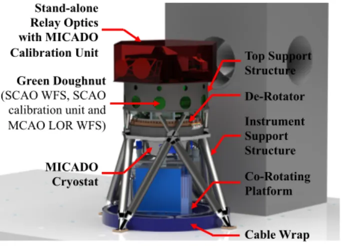
Stand-alone Relay Optics with MICADO Calibration Unit Green Doughnut (SCAO WFS, SCAO
calibration unit and MCAO LOR WFS) MICADO Cryostat De-Rotator Instrument Support Structure Top Support Structure Co-Rotating Platform Cable Wrap
Figure 1. MICADO at the telescope in its standalone configuration, i.e. with the SCAO module alone and a dedicated optical relay.
1. INTRODUCTION: MICADO OVERVIEW
MICADO is the ELT first light-imager.1,2 Working in the near-IR (0.8-2.4 µm) at the ELT diffraction limit, it will offer four observing modes:
• Standard imaging: with 1.5 & 4 mas pixel scales, the corresponding FoV will be 19 & 51 arcsecond2. More
than 30 broad-band & narrow-band filters will be available
• Astrometric imaging: it drives MICADO design, with a gravity invariant implementation, a fixed mirror optical design, state-of-the-art ADC and dedicated astrometric calibration and data pipeline
• High contrast imaging: it will use the central detector and will be enabled via a classical configuration of focal plane coronagraphs and Lyot stops, as well as pupil plane vAPP coronagraphs and sparse aperture masking. Pupil tracking will be available for angular differential imaging3
• High resolution spectroscopy: it will provide coverage of a wide wavelength range simultaneously (1.15-1.345 µm, 1.48-2.45 µm or 0.845-1.48 µm) at a resolution of ∼20000 on faint compact or unresolved sources. Three slits will be available: 300×16 mas, 1500×20 mas (for sky subtraction along the slit), 300×48 mas (wide)
MICADO will benefit from the Multi-Conjugate Adaptive Optics (MCAO) correction provided by MAORY,4
for which MICADO’s design is optimized. MICADO will also benefit from a SCAO correction developed under MICADO’s responsibility and jointly by MICADO and MAORY. This SCAO module will be integrated in MAORY. In case of a delay in the development of MAORY, MICADO will be commissioned at the telescope first-light in a stand-alone configuration with a specific optical relay and with the SCAO module alone (Fig.1). In any case, in a phased approach of the AO integration at the ELT, SCAO will be the first AO mode to be tested with MICADO at the telescope.
MICADO’s planning is the following:
• 2018, Nov.: (successful) preliminary design review • 2020, Oct.: final design review
• 2024, June: preliminary acceptance Europe
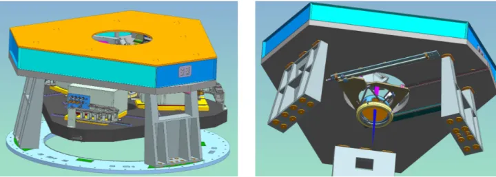
Figure 2. Left: The GD with the baffled SCAO parts on the top and the MAORY MCAO NGS WFS at the bottom. Right: Bottom view of the SCAO bench, with the deployable dichoic plate assembly.
2. MICADO-MAORY SCAO PRELIMINARY DESIGN
2.1 SCAO Green Doughnut and dichroic plate
The Green Doughnut (GD) is a volume hosting in its upper part the SCAO module and in its lower part the MAORY MCAO NGS WFS (Fig. 1 and 2 left). The SCAO GD structure is made of 1) the optical bench supporting the SCAO WFS and the SCAO calibration unit, 2) its feet connecting the bench to the MICADO cryostat interface and 3) below the bench, the SCAO dichroic plate assembly (Fig. 2and3left).
The SCAO GD structure has stringent specifications: • SCAO envelop limited to 2.8m×0.4m
• Mass budget limited to 620 kg
• First eigen frequency greater than 50 Hz
• Low CTE to ensure optical alignment over the ESO-specified environmental conditions
These specifications are fulfilled thanks to a carbon fiber bench with a baffling and pods contributing to the structural stability.
The SCAO dichroic plate is removable for MCAO operations. Its tilt (18◦) allows to escape the MCAO NGS patrol FoV with an acceptable vignetting while keeping the induced astigmatism limited. This ∅340mm×30mm dichroic plate has a slight wedge on its rear surface to compensate for the lateral shift of the pupil it introduces at the entrance of the cryostat
2.2 SCAO WFS
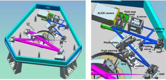
The SCAO WFS is based on a (double) pyramid WFS. It is sensing the wave-front between 0.589 and 0.96 µm with a ∅200 FoV. Critical functionalities of the WFS are: pupil control & guiding, field patrolling, atmospheric dispersion compensation, NCPA management, wave-front sensing itself. We describe hereafter how these func-tionalities are addressed in the SCAO design (Fig.3 right).
Pupil guiding is handled thanks to:
• A pupil imaging lens (PIL) system, located between the WFS camera and the pyramid, in charge of the managing the small pupil offsets
• A pupil steering mirror, located at the entrance of the WFS, in charge of managing large (and rare) pupil offsets
Figure 3. Left: Opto-mechanical design of the WFS (blue rays) and SCU in its final on-sky configuration (magenta rays). Right: Zoom on the WFS components (the pupil imaging camera is not represented).
• A K-mirror stabilizing the pupil in rotation, whose stringent specifications (∼0.1 λ/D shift over 6◦rotation)
have motivated specific prototyping5
A field selector at the entrance of the WFS allows:
• To select, finely position and track the AO target in the SCAO 600×2000patrol FoV
• To correct for the differential image position between IR and visible • To manage dithering/offsets and differential tracking
Near an intermediate pupil plane an assembly gathers several components:
• A phase plate assembly, dedicated to the compensation of NCPA between the WFS and the cryostat, supporting three phase plates (one for the dichroic astigmatism, one for this astigmatism and the fixed cryostat low order aberrations, and one neutral)
• An ADC, made of two rotating prisms • A neutral density positioner
• The modulation mirror, specified at ±0.1 mrad @ 500 Hz and 1 mrad @ 50 Hz The sensing is performed thanks to:
• An achromatic 20mm×20mm×39mm double pyramid in a F/30 beam
• An ESO in-development ALICE camera based on the E2V CCD220 detector with 240×240 pixels, allowing to image the four pyramid pupils of 96 pixel-diameter each
The WFS also integrates:
• A pupil viewing camera, sampling finely the pupil for AIT & maintenance • Calibration sources, including for reference slopes, at the entrance of the WFS
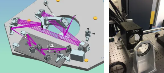
Figure 4. Left: The SCU in AIT configuration, with a breadboard supporting the AIT components. Right: ALPAO 64×64 DM @ Meudon (co-funded by R´egion Ile-de-France/DIM ACAV and CNRS/INSU).
2.3 SCAO calibration unit
The SCAO calibration unit (SCU) is the SCAO test, calibration and maintenance facility. During its lifetime it will know successively an AIT and an on-sky configuration.
In AIT configuration (Fig.4 left), the SCU will be used during the AIT phases in Meudon and in the MPE hall in Garching. It will allow to perform the integration and performance tests of the SCAO module. For this purpose, it will be equipped with:
• A newly developed and recently delivered ALPAO 64×64 actuator deformable mirror (DM), currently under tests in Meudon (Fig.4 right). It will be used in the final AIT phase in Meudon for the validation of the SCAO performance6,7
• A slow tip-tilt mirror (TTM) allowing with the 64×64 DM to mimic the ELT M4+M5 configuration • Turbulent phase screens, pupil masks and calibration/alignment sources
SCU will be turned into its final on-sky configuration when MICADO moves to ESO X4 hall in Garching, removing the turbulent phase screens, the pupil masks and the TTM, and replacing the 64×64 DM by a low order DM (so-called XDM) dedicated to NCPA calibration (Fig.3left).
2.4 SCAO real-time computer
SCAO real-time computer (RTC) design is based on developments made in Observatoire de Paris in the framework of the Green Flash project that are now going on with the COSMIC initiative (gathering Observatoire de Paris, Microgate and the Australian ANU and SUT) that aims at building an RTC platform, modular to adapt to various AO systems8
SCAO RTC will follow the functional architecture defined by ESO, dividing the RTC into a Hard Real-Time Core (HRTC), a Soft Real-Time Cluster (SRTC) and a Communication Infrastructure.
A classical control law is considered using MVM with up to 25.5k measurements (expanded space control or so-called ”full pixel” control9) and 5.4k commands at 500 Hz. Considering the allowed 285 µs latency for
computation, it leads to a required 1700 GB/s memory bandwidth in single precision for the HRTC. The maximum data transfer rate for telemetry (considering calibrated pixels, residual modes, DM commands, etc) is 2 Gb/s (in double precision) while the required compute throughput for the supervisor, related to the command matrix optimisation task, performed about every minute, is 314 GFLOP.
The HRTC design is based on hardware (HW) acceleration using NVIDIA GV100 GPU, equipped with HBM2 high memory bandwidth. It will make use of a Microgate FPGA-based HW interface and the GPU direct feature
Compute pipeline: Marlin Octopus Marlin Unit Marlin Unit Marlin Units
CPU SHM GPU SHM FPGA
Marlin Unit Marlin Unit Marlin Units Octopus
Telemetry Hardware Simulator
Controller: Kraken Redis database Marlin Unit Marlin Config Daemon Synchronize parameters between database and FPS Marlin Business Unit Implements the computation kernel Octopus: FPS interface
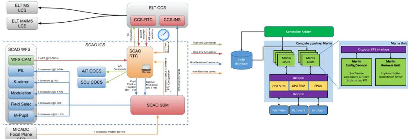
Figure 5. Left: overview of the different controls and data transfers at play for SCAO, involving both the instrument control software (and the corresponding ESO instrument control system framework modules) and the RTC. Right: HRTC core architecture, featuring the different HRTC SW levels.10
allowing to directly transfer the WFS camera data to the GPU. The HRTC software (SW) stack is divided in 3 levels: an interface module (called Octopus), the core compute engine (called Marlin) and the user interface (called Kraken)10(Fig. 5right).
The SRTC HW will be made of a GPU server while the various functional blocks of the SRTC SW will be assembled around the telemetry middleware to send / receive data from the HRTC module. On top of this, the control middleware is used by the supervisor SW to send commands to the HRTC software to perform observing sequences and optimize operations.
2.5 SCAO performance estimation
SCAO performance has been estimated with our GPU-based COMPASS platform that allows fine sampling (e.g. 512×512 pixel support for our SCAO final pyramid image) and fast simulation even at the ELT scale. It is installed on a computer equipped with 2 CPU Intel(R) Xeon(R) CPU E5-2630 v4 @ 2.20GHz (10 cores each) with 64GB RAM and 8 NVIDIA Titan X (Pascal) GPU cards.
For MICADO PDR, we performed AO simulations11 to
• Demonstrate the better performance of the pyramid WFS vs. Shack-Hartmann WFS
• Demonstrate the gain in performance using (Korkiakoski12) pyramid optical gains (though computed with
an unrealistic method, with 2 interaction matrices obtained by simulation: one diffraction limited, one under close loop conditions)
• Demonstrate the interest of the ”full pixel” centroiding method that virtually cancels any static misalign-ment of the pyramid WFS pupils and relaxes dramatically the specifications on the pyramid angles • Optimize the pyramid WFS parameters in terms of
– Pupil sampling: performance plateau between ∼88 et ∼100 pixels for the diameter of the four pyramid pupils. Our current baseline is 96 pixel diameter pupils.
– Number of filtered modes vs. guide star magnitude: ∼10 for a 12 magnitude reference source, ∼200 for a 15 magnitude reference source and up to 3000 for a 17 magnitude reference source, under median atmospheric conditions
– Modulation amplitude vs. guide star magnitude: current baseline is 5λ/D
• Estimate island effect residuals (differential pistons over the ELT pupil petals), when simply forcing phase continuity over the pupil by slaving the actuators pair-wise on each side of the spiders: 125 nm rms under median atmospheric conditions
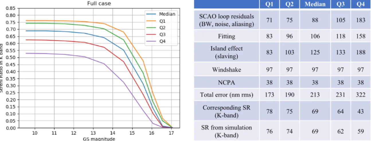
Q1 Q2 Median Q3 Q4
SCAO loop residuals
(BW, noise, aliasing) 71 75 88 105 183 Fitting 83 96 106 118 158 Island effect (slaving) 83 103 125 133 188 Windshake 97 97 97 97 97 NCPA 38 38 38 38 38 Total error (nm rms) 173 190 213 231 322 Corresponding SR (K-band) 78 75 69 64 43 SR from simulation (K-band) 76 74 69 62 59
Figure 6. SCAO performance including turbulence, NCPA compensation, windshake and island effect. Left: Performance vs. the guide star magnitude for the different ESO atmospheric conditions. Right: Corresponding error budget for R=12.
• Estimate windshake residuals from simulated ELT guide probe measurements: 97 nm rms under median atmospheric conditions
• Validate our NCPA management strategy, using a phase plate in the WFS design together with reference slopes+pyramid optical gain
We then derived the SCAO performance for various turbulence conditions and point-like reference source magnitudes as well as a global SCAO error budget (Fig.6). The complete SCAO error budget is obtained from these end-to-end AO simulations and additional instrumental error terms (130 nm rms left for these instrumental contributors to fulfil the SCAO performance specifications of SR=60%, i.e. 250 nm rms).
Since PDR, major developments in terms of AO simulations are concerning:
• The pyramid optical gains estimation, with the development of our new ”CLOSE” method that allows a robust estimation, in real-time, of these gains from previous WFS measurements13 (see e.g.
https: //tinyurl.com/singleStarCLOSE).
• The performance estimation for double/extended reference sources,11 demonstrating basically that
– the SCAO performance depends on the double star components on sky orientation and separation (Fig.7 right andhttps://tinyurl.com/doubleStarCLOSE)
– when the difference of magnitude between the double star components is larger than 1.75 the perfor-mance is equivalent to the single star case
– the performance is preserved with reference sources with a diameter up to 0.800 (Titan case,https: //tinyurl.com/TitanCLOSE)
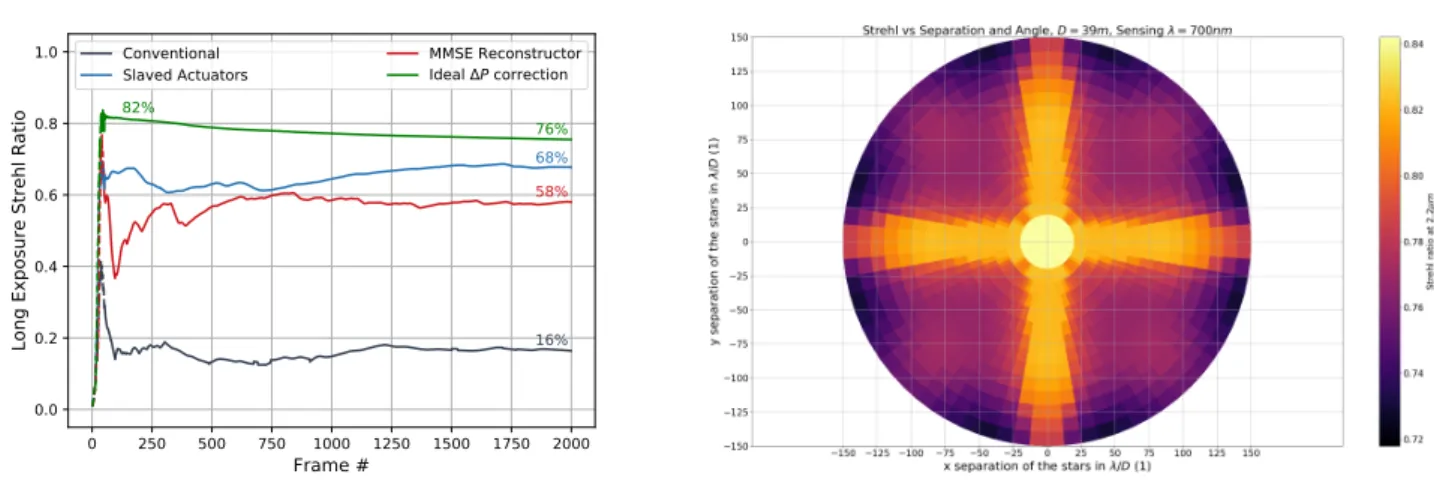
• The development of a new island effect management strategy based on a MMSE reconstructor filtering piston per segment together with an estimation of the missing differential piston component based on Kolmogorov statistics14 (Fig.7 left)
3. MICADO-MAORY SCAO DEVELOPMENT PLAN
3.1 The CANARDO on-sky demonstration and the SCAO prototyping activities
During the manufacturing phase, in 2021, our development plan includes an on-sky demonstration of our WFS core (double pyramid + PIL + modulation) + RTC prototype using the ALPAO 64×64 actuator DM and an OCAM2 camera (ALICE not yet delivered). It will be performed on the CANARY bench at WHT.
0 250 500 750 1000 1250 1500 1750 2000 Frame # 0.0 0.2 0.4 0.6 0.8 1.0
Long Exposure Strehl Ratio 16%
68% 58% 76% 82%
Conventional
Slaved Actuators MMSE ReconstructorIdeal P correction
Figure 7. Left: Performance of various island effect management strategies: actuator slaving (blue), MMSE-based14(red), ideal differential piston sensor (green). Black line is the performance in case of no island effect correction. Right: K-band performance for a R=11 double star reference source vs. double star components separation and angle.11
The goals of this demonstration are to check the proper functioning of the WFS hardware and to test the algorithms to be implemented in the SRTC, in particular their robustness to variable turbulent conditions (optimized modal gains, NCPA & island effect management, etc).
For that purpose, the manufacturing of the WFS core will be launched in advance to the project manufacturing phase. Tests of the WFS core + RTC prototype will done beforehand in our ATLAS AIT lab.
In parallel, pyramid WFS and K-mirror prototyping is performed in our Sesame lab together with the development of our field selector proto-flight model.
3.2 AIT milestones
In Meudon, the SCU (in its AIT configuration) and WFS will be integrated on separate optical benches but tested together. Performed tests will be: alignment and mounting procedures, internal interfaces verification, functional tests, NCPA procedure validation, software (ICS, SRTC) tests and continuous improvement, per-formance measurements. After the GD structure test with a specific test-bed, the SCU (AIT configuration) and WFS will be integrated on the GD to perform tests similar to the aforementioned ones (in particular AO performance).
In Garching, first tests with MICADO will be in the MPE hall (always with the SCU in its AIT configuration): external interfaces verification (mechanical, cabling, software), common optical alignment, NCPA measurements to build the final phase plates, performance measurements with MICADO. Tests with MICADO in its final configuration at the ESO X4 hall will be done with the SCU in its on-sky configuration. SCAO will be then shipped to Chile.
In Bologna, AIT with MAORY will be done with duplicated or dummy parts to check mechanical interfaces and interlock safety systems.
4. MICADO MAORY SCAO CALIBRATION STRATEGIES
4.1 Calibrations during AIT in Europe
These calibrations will be two-fold:
• Fixed and recurrent general calibrations at sub-system or system level, in particular: matching MICADO vs. SCAO coordinate systems, phase plate manufacturing, SCU photometry, MICADO plate scale, MICADO slits and coronagraph masks positions in SCAO field selector space, XDM & HODM command matrices, reference slopes for full turn of K-mirror and ADC, PIL interaction matrix, WFS detector calibration
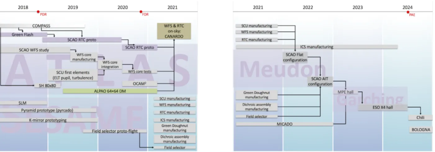
Figure 8. Left: MICADO-MAORY SCAO development plan till 2021, emphasizing the prototyping activities and the path to the CANARDO experiment. Right: MICADO-MAORY SCAO development plan after 2021, emphasizing the successive AIT phases.
• AO loop related calibration: WFS calibration against a modal basis larger than M4 with a large interaction matrix allowing to cope with any DM (provided we know its mode influence functions)
4.2 Calibrations during commissioning
These calibrations will either:• Not use ELT observing time: calibrations done during AIT in Europe will be redone during commissioning for verification (see above)
• Use ELT observing time, requiring a fully functional ELT:
– Verifications of various settings/parameters supposedly known from design (signs/orientations of off-sets, of pupil, of K-mirror rotation, etc)
– Verifications related to M4/M5: M4 modes/actuators on-sky orientation, scale of M5 motion, ESO-provided M4 modal influence functions (spatial aspects), RTC latency to M4
– Non-AO calibrations: field selector scale + registration with respect to MICADO detector, secondary guiding adjustment, transmission, etc
– AO-loop calibrations: closing the loop with an increasing number of modes, checking for the pupil guiding, M4 registration tracking, pyramid optical gain tracking
– TLR verifications: SCAO performance (SR vs. magnitude & seeing)
4.3 Calibrations during operations
SCAO is designed with the goal of minimizing the calibration phases during the instrument lifetime at the telescope and then lowering the impact on the observatory operation. In particular, the SCAO calibration unit delivered in the SCAO module is meant to allow us to perform calibrations internally without interfering with any activity at the ELT.
During daytime:
• NCPA can be re-calibrated, on demand according to the on-sky image quality (estimated calibration time: 3h/yr)
• Verification of SCAO good functioning by running each day a ∼10 min template During night time:
• M4 influence functions: we rely entirely on ESO providing these as-built M4 influence functions and no calibration of the influence functions is foreseen
• M4 interaction matrix: this calibration is performed during commissioning at night (no calibration source is available in the telescope) and is not planned to be re-calibrated (relying on ESO confidence in M4 + telescope stability)
• Optimization tasks done in background to observations: modal gains computation for command ma-trix optimisation and NCPA compensation, M1 & M4 registration, WFS detector background, wind-shake/vibration management, M1 missing segments
ACKNOWLEDGMENTS
The purchase of the ALPAO 64×64 actuator deformable mirror has been funded by a grant from DIM ACAV/R´egion Ile-de-France and thanks to the financial support of INSU. Its tests and characterization have been supported also by INSU and Observatoire de Paris through the funding of J. Raffard’s position.
REFERENCES
[1] R. Davies, J. Alves, Y. Cl´enet, et al., “The MICADO first light imager for ELT: overview and operation,” in Ground-based and Airborne Instrumentation for Astronomy VII, Proc. SPIE 10702, 2018.
[2] R. Davies et al., “MICADO sci-ops: shaping its adaptive optics systems,” in Proceedings of the AO4ELT6 conference, 2019.
[3] E. Huby, P. Baudoz, F. Vidal, et al., “MICADO lyot coronograph performance study,” in Proceedings of the AO4ELT6 conference, 2019.
[4] P. Ciliegi, E. Diolaiti, R. Abicca, et al., “MAORY for ELT: preliminary design overview,” in Adaptive Optics System VI, Proc. SPIE 10703, 2018.
[5] S. Thijs, O. Dupuis, E. Gendron, et al., “K-mirror prototype for the MICADO SCAO module,” in Proceed-ings of the AO4ELT6 conference, 2019.
[6] F. Vidal, J. Raffard, E. Gendron, et al., “Tests and characterizations of the ALPAO 64×64 deformable mirror, the MICADO-MAORY SCAO AIT facility,” in Proceedings of the AO4ELT6 conference, 2019. [7] P. Mahiou et al., “New deformable mirrors available for the ELT and future developments,” in Proceedings
of the AO4ELT6 conference, 2019.
[8] D. Gratadour et al., “The COSMIC real-time control platform,” in Proceedings of the AO4ELT6 conference, 2019.
[9] V. Deo, E. Gendron, G. Rousset, et al., “Assessing and mitigating alignment defects of the pyramid wavefront sensor: a translation insensitive control method,” A&A 619, p. id. A56, 2018.
[10] F. Ferreira, A. Sevin, J. Bernard, and D. Gratadour, “MICADO-MAORY SCAO RTC system prototyping: assessing the real-time capability of GPU,” in Proceedings of the AO4ELT6 conference, 2019.
[11] F. Vidal, M. Rozel, V. Deo, et al., “Analysis the MICADO-MAORY SCAO performance,” in Proceedings of the AO4ELT6 conference, 2019.
[12] V. Korkiakoski, C. V´erinaud, and M. L. Louarn, “Applying sensitivity compensation for pyramid wavefront sensor in different conditions,” in Adaptive Optics Systems. Proceedings of the SPIE, 7015, p. id. 701554, 2008.
[13] V. Deo, M. Rozel, A. Bertrou-Cantou, et al., “CLOSE: a self-regulating, best-performance tracker for modal integrator based AO loops,” in Proceedings of the AO4ELT6 conference, 2019.
[14] A. Bertrou-Cantou, E. Gendron, G. Rousset, et al., “Analysis of the island effect for MICADO-MAORY SCAO mode,” in Proceedings of the AO4ELT6 conference, 2019.