The Design and Testing of a Biologically Inspired
Underwater Robotic Mechanism
by
Michael Sachinis
Submitted to the Department of Mechanical Engineering
in partial fulfillment of the requirements for the degree of
Master of Science in Mechanical Engineering
at the
MASSACHUSETTS INSTITUTE OF TECHNOLOGY
June 2000
@
Massachusetts Institute of Technology 2000. All rights reserved.
Author ...
...
Department of Mechanical Engineering
/i
May 8, 2000
Certified by...
Michael S. Triantafyllou
Professor, MIT
Thesis Supervisor
R ead by ...
David L. Trumper
Professor, MIT
T4smm-eader
Accepted by
Ain A. Sonin
Chairman, Department Committee on Graduate Students
MASSACHUSETTS INSTITUTE OF TECH1NOLOiY
The Design and Testing of a Biologically Inspired
Underwater Robotic Mechanism
by
Michael Sachinis
Submitted to the Department of Mechanical Engineering on May 8, 2000, in partial fulfillment of the
requirements for the degree of
Master of Science in Mechanical Engineering
Abstract
This thesis describes the design, construction and testing of the new generation Robo-tuna, a laboratory six-joint robotic mechanism intended to imitate the motion and function of a real size bluefin tuna. Attached to a towing carriage in the MIT Testing Tank Facility, this mechanism was designed as an improved form and substitute of the original robot, built in 1993. Major issues of design as well as performance re-sults from its four-month life are discussed in detail. Finally, the issue of flow sensing around its flexible hull is addressed and first steps towards this implementation are described.
Thesis Supervisor: Michael S. Triantafyllou Title: Professor, MIT
Acknowledgments
I would first like to express my sincere gratitude towards my advisor, Prof. Michael
Triantafyllou, and towards Dr. Franz Hover for the unlimited guidance and support they have offered me, for supervising my thesis and for giving me the opportunity to work in a great engineering environment.
Special thanks also go to Prof. D. Trumper for being extremely accommodating and taking the time to read my thesis, and to Ms. Regan for her remarkable patience.
My extended gratitude also goes to Fred Cote who patiently guided me in paths
of engineering that I had never explored before, who never complained when I broke or borrowed tools and who taught me the value of persistence in machining. I hope the days of polypropylene tubing will one day be remembered as a nice memory.
I would also like to thank all the graduate and undergraduate students working
in the Towing Tank, for transforming a dark underground laboratory to such a nice working environment, even during long nights of stressful work. Special thanks go to David Beal, with whom I worked very closely on the Robotuna project, and whose guidance and good humor made it more enjoyable and certainly more educational. I am confident that he will take good care of the Robotuna, and I wish that the Robotuna will reward him with good results in the future. Special thanks also go to Michael Jakuba, Katherine Reid and Kate Thompson for taking a large part of the Robotuna's weight on their backs and for doing such a great and professional work.
MIT would not have been such a fun place without the presence of a certain group of Mediterranean people. I wish them all good luck in their studies and work and expect to see them soon in a warmer place.
My deep gratitude also goes to my parents for their unlimited love and support
and for so many years of sacrifice towards my education, to my brother for he has been a source of great encouragement, and to my uncle Harry for truly being a second parent. Most importantly, I would like to thank my stepfather, George, for believing in me and offering me opportunities that would have only been a dream without him.
Finally, I wish to thank Mayssam for being a true pillar of support, comfort, guidance and happiness at MIT. She has helped me in unimaginative ways. I hope these will be more than memories of the past. She has made it extremely difficult for me to leave MIT, and has encouraged me tremendously to return.
Contents
1 Introduction 12
2 Design Aspects of the New Robotuna
2.1 Design Philosophy ...
2.2 Actuation Considerations ...
2.2.1 Competing Systems of Actuation . . . .
2.2.2 Tendon Drive System . . . .
2.2.3 Reflections to the Transmission System Design .
2.3 Position Sensor Considerations . . . . 2.4 External Shape Design Considerations . . . .
2.4.1 Relevance of the Problem . . . .
2.4.2 Design Concerns over the Skin and Ribs . . . .
2.4.3 Design Solutions on Skin and Ribs . . . .
2.4.4 Nosecone Design . . . .
2.4.5 Peduncle and Tail Regions . . . . 2.4.6 Fins and Finlets . . . .
2.5 Evaluation of the Robotuna's Design . . . .
3 Testing and Performance of the New Robotuna
3.1 Preliminary Test Results . . . .
3.1.1 Primary Test Objectives . . . .
3.1.2 Straight Drag Results . . . .
3.1.3 First Genetic Algorithms on the New Robotuna
15 . . . . . 15 . . . . . 17 . . . . . 17 . . . . . 20 . . . . . 31 . . . . . 33 . . . . . 36 . . . . . 36 . . . . . 37 . . . . . 38 . . . . . 40 . . . . . 42 . . . . . 42 . . . . . 43 46 46 46 50 53
3.2 3.3 3.4
A Model for the Frictional Losses . . . .
Further Genetic Algorithm Results . . . . Recommendations for Future Work . . . .
4 Pressure Measurements of the Flow Around the
4.1 M otivation . . . .
4.2 Design Alternatives and Other Considerations . .
4.3 Tube Dynamics . . . .
4.3.1 Modeling of the Dynamic Effects of tubing 4.3.2 Testing of the Model . . . . 4.4 Future Pressure Tests on the Robotuna . . . .
5 Concluding Remarks . . . . . . . . . . . . New Robotuna . . . . . . . . . . . . . . . . . . . . . . . . 56 64 70 73 73 75 81 81 85 88 89
List of Figures
2-1 A close look to the passive joint connecting the plate of the nosecone to the
main body of the Robotuna. . . . . 17
2-2 Detailed view of the tail end of the Robotuna, showing the large peduncular
link that supports the lateral keel mechanism. . . . . 18
2-3 General view of the bar-linkage system, as it was conceived in the early
stages of the design of the Robotuna. . . . . 19
2-4 Actual angular position of the tail joint as a function of the previous joint angle alone. The deviation from the dotted red line shows imperfect coupling. 22
2-5 A schematic description of the fundamental difference in the idler pulley
arrangement between the new and the old Robotuna. In the new Robotuna design, the rotation of a link leaves the orientation of the next link unaffected (perfect coupling). This is not the case with the old design, where the next
link is expected to rotate by an equal amount (decoupling). . . . . 23
2-6 Cost function used for the minimization of the angular uncertainty in joint 4. 25
2-7 Side view of the lateral keel section in a real tuna. Courtesy of M.W.Westneat
et al.[11] . Though the disc-shaped form is not clearly shown, the curving
of the great lateral tendons (GLT) is obvious. . . . . 26
2-8 Demonstration of perfect coupling principle in the case of a bar-linkage
actuation system. The rotation of the second link leaves the following links
2-9 Closeup view of the compound-pulley configuration as was implemented in the case of joint 1. A pair of blue pulleys is allowed to slide along the white delrin channel. In reality, this pair is cable connected to a second pair (not shown) axially located on the left joint. Finally, a short cable (not shown) connects the sliding pulleys to the side of the bulkhead of the right joint. . 28
2-10 Schematic diagram of Compound Pulley System. The pulley at the left is fixed while the one diagonally to the right is allowed to slide, thus rotating
the bulkhead that is attached to. . . . . 30
2-11 Abstraction of the Compound Pulley system of Figure 2-10, showing the
similarity to a perfectly decoupled transmission system. . . . . 30
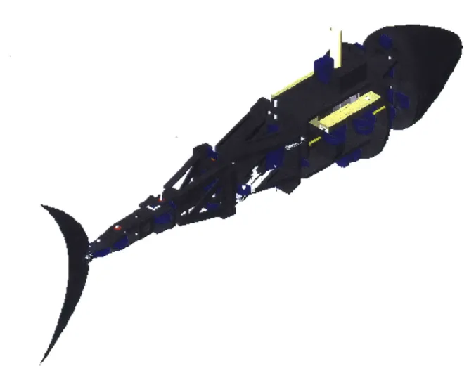
2-12 Overview of the final assembly of the new Robotuna, as designed in
Solid-Works by D. Beal and the author. . . . . 32
2-13 Schematic of the DVRT set up as it changes position with different angles.
The purple circle designates the size of the bearing mounted on the relevant joint. The green segment describes a fixed distance from the center of the joint to the attached bulkhead. The DVRT is mounted on the red line (of variable length). The black and blue lines are legs of constant length, fixed
or pinned to the rest of the mechanism. . . . . 34
2-14 The purple line shows the functional relation between DVRT core dis-placement and joint rotation for joint 4. Extreme angle positions at
0 and 60 degrees (straight fish at 30 degrees). Monotonicity is
pre-served but not linearity, as the deviation from the ideal red line shows. Sensitivity is also expected to be lost near the lower extreme. . . . . . 35
2-15 Closeup view of the DVRT placement for joint 4. . . . . 36 2-16 General view of the spine and rib design. . . . . 39 2-17 Wooden nose model and actual nosecone, thermoformed from a square PVC
sheet . . . . .... ... ... . . . .... . . . .... ... 41
2-18 The new Robotuna posing at the final stages of its assembly. The cables
have not been threaded yet. . . . . 45
3-1 First Straight Drag measurements on the new Robotuna and a parabolic fit. These have been very consistent with later measurements during the first
four months of operation. . . . . 51
3-2 Coefficient of friction based on a total wetted area of 0.59m2. . . . 51
3-3 Diagram showing the 8
th generation of the first genetic algorithm performed
on the new Robotuna. As most parameters have reached convergence, it seems that the best swimming style can produce approximately 1.5 times its drag at 0.6m/s, at an efficiency close to 15%. The two low-thrust cases
correspond to badly mutated offsprings of the generation. . . . . 54
3-4 Second genetic algorithm performed on the new Robotuna. Only the last
three generations are shown. The swimming parameter has a strong weight, a = 0.25 and prohibits convergence. Indication of an efficiency barrier near
15% is clear. . . . . 55
3-5 Decay in the total power expended to friction in air, as the Robotuna's
components become dry. Courtesy of D. Beal. . . . . 58
3-6 Internal friction coefficients for each joint, calculated from a linear model for friction, as functions of frequency of swimming. Green and red data points correspond to joints 0 and 1 and are the highest. Blue, magenta and black
points describe joints 2, 3 and 4. Total of runs: 73 . . . . 60
3-7 Internal friction coefficients for each joint, calculated from a linear model for friction, as functions of Strouhal number. Data seem coherent with a down-ward slope which suggests the existence of a Coulomb friction component.
Total of runs: 73 . . . . 60
3-8 Measured (red points) and computed (blue line) power expenditure to
fric-tion for joint 0, for a total of 73 runs. The linear-Coulomb model seems
within 5% accurate for most runs. . . . . 61
3-9 Measured (red points) and computed (blue line) power expenditure to
fric-tion for joint 1, for a total of 73 runs. As for joint 0, scatter is surprisingly
3-10 Comparison between measured and computed power requirements for joint 1. Agreement is very close for power levels up to 1.lWatt, which describe
most swimming styles . . . . 62
3-11 Measured (red points) and computed (blue line) power expenditure to
fric-tion for joint 2, for a total of 73 runs. . . . . 63
3-12 Measured (red points) and computed (blue line) power expenditure to
fric-tion for joint 3, for a total of 73 runs. The accuracy of the model is clearly
less than for the first joints. . . . . 63
3-13 Measured (red points) and computed (blue line) power expenditure to
fric-tion for joint 4, for a total of 73 runs. The model fails completely to follow
the data. . . . . 65
3-14 Genetic algorithm with circular SWP and a "real" propulsive efficiency that
dismissed frictional losses . . . . 66
3-15 Genetic Algorithm with a modified efficiency metric and a linear SWP. . . 68 3-16 Genetic Algorithm intended to investigate low thrust-high efficiency
swim-m ing styles . . . . . 69
4-1 Circuit diagram for the ASCX05DN pressure sensor unit. . . . . 78
4-2 Cluster Array of 12 Pressure Sensors. . . . . 79
4-3 Arrangement of cluster of pressure sensors on the mast of the tuna. Nalgene
tubes run through the mast and into the fish. . . . . 80
4-4 Schematic block diagram describing the main components that participate
in the tube dynamics. . . . . 82
4-5 Reduced block diagram representation for the tube dynamics. . . . . 83
4-6 Frequency spectrum of pressure trace when the tubes are filled mostly with
air. . . . . 8 6
4-7 Frequency spectrum of pressure trace when the tubes are filled mostly with
List of Tables
3.1 Mean and standard deviations of actual power expended in the joints from
the linear-Coulomb model. . . . . 61
3.2 Linear and Coulomb friction coefficients used to model frictional power
losses. The coefficients for joint 4 were not used . . . . . 64
3.3 Summary of some of the best runs obtained from various genetic algorithms.
The seven defining parameters include Strouhal number (St), tail-foil angle of attack (a), phase between heave and pitch (<0), heave amplitude (in cm),
Chapter 1
Introduction
The original Robotuna was designed and built in the MIT Ocean Engineering Testing Tank Facility in 1993, as a response to the need for highly maneuverable underwater vehicles of greater autonomy in oceanographic and military applications. The design of the Robotuna, conceived by graduate student David Barrett, was an attempt to imitate the biological shape form and motion of a medium sized bluefin tuna. This decision was based on the popular notion in the robotics community that nature has solved the issue of propulsion through evolution of its species and should therefore be a major source of study and inspiration for man-made propulsion systems. Thus, studying the motion of such an advanced swimmer that can cross oceans in the course of days and can allegedly produce instantaneous speeds up to 50 miles per hour, seemed like a logical start.
Inside its tuna-like body, the Robotuna consisted of a cable-driven robotic arm of six degrees of freedom that was rigidly connected to an overhanging carriage by means of a surface-piercing hydrofoil mast. The depth was thus constrained and the robotic mechanism was allowed to swim in straight paths only. Furthermore, the rigid connection to the carriage allowed all instruments and motors to be positioned in a dry and spacious environment.
During its first years of operation, the Robotuna participated in a large number of experiments that were targeted towards the development of an optimally efficient swimming style by means of a genetic algorithm approach. Moreover, dye injection
and laser visualization techniques were applied repeatedly in an effort to shed light to the mysteries of efficient fish swimming.
More than five years after its construction, it was apparent that the Robotuna had aged significantly and was unable to produce the performance levels that were reported in its early history. Furthermore, many of its mechanical parts had shown distinct signs of corrosion and decay, as they had far exceeded their intended design life of a few months. As a consequence, most measurements that were critical in the performance evaluation were deemed to be unreliable and imposed a halt to the testing process. Efforts were subsequently made by graduate student Sam Tolkoff to replace certain parts of the tuna and proceed in a partial restoration, but they marked only limited success [16].
Assessing the level of degradation based on Tolkoff's inspection analysis and ad-hering to the desire for a more advanced Robotuna with extended capabilities, it was decided that the second generation of tuna should be developed. The task was undertaken by graduate student David Beal and the author in the spring of 1999. This called for the design and construction of an entirely new swimming mechanism that could produce satisfactory performance levels, increase the reliability of position and force sensor outputs and ultimately possess higher "intelligence" capabilities by detecting the characteristics of its surrounding flow and responding accordingly to maximize its thrust or efficiency.
This effort has been under way for one year and while the new Robotuna has been swimming smoothly for nearly four months, the project is still far from its final conclusion. In this thesis, the author offers a detailed description of certain design aspects of the new Robotuna where he was primarily involved in. Some of the relevant work of graduate student David Beal and undergraduate students Michael Jakuba, Katherine Reid and Kate Thompson is also mentioned briefly for the purpose of completeness and in order to portray a more clear picture of the overall robotic mechanism. Issues relating to the general architecture of the model are discussed extensively with emphasis on the principles behind the actuation system design, and some evaluation based on primary results has been attempted. Initial performance
results, based on an early set of genetic algorithms, are mentioned and backed with suggestions and recommendations for the future. In a later chapter, the idea of further "intelligence" capability is introduced and the design of an artificial lateral line sensor array as well as a large scale vorticity production mechanism are described and evaluated.
It is hoped that this piece of writing may stand as an accurate report of what has transpired in the early stages of life of the new Robotuna, and may be a useful means of pointing out the strengths and weaknesses of the mechanism, so that improvements will be made in the near future and the main goal of the investigation will be fulfilled.
Chapter 2
Design Aspects of the New
Robotuna
2.1
Design Philosophy
The design of the new Robotuna was based on the principles of Barrett's fish. The simplicity of Barrett's mechanism and its success in imitating the undulating motion of a cruising tuna suggested that the new generation should by an improved offspring of the original version rather than a complete stranger to it [1]. Furthermore, by keeping the design philosophy unchanged, it would be easier to tackle specific prob-lems and limitations that were identified in the old tuna, especially towards the late stages of its life. Finally, by adopting a similar structure and testing methodology, we would be allowed to make more accurate comparisons between the two generations.
Like Barrett's fish, the new Robotuna was designed as a test bed for an efficient, straight line swimmer. Combining efficient cruising with swift maneuvering capabili-ties is a task kept for future generations. Consequently, it was decided that autonomy was not required yet and the new mechanism could still be supported by an over-hanging carriage that would provide depth control, and at the same time level the fish and host the powerful motors that actuate it as well as most of the necessary
elec-tronics. This decision simplified the design considerably and offered valuable space that was desperately needed, especially near the tail section. Moreover, it reduced
the dynamics of the overall system to that of an extended arm linkage mechanism that could swing in the horizontal plane only, with a total degree of freedom equal to the number of independent joints.
Having preserved these fundamental aspects of the old tuna mechanism, David Beal and the author defined our new design philosophy to target four areas that required change or offered room for further improvement. The first one involved the addition of new external features to the body, so that the Robotuna would follow more faithfully the shape of a real bluefin tuna. It was considered that details in the shape that were ignored in the first model might be responsible for secondary hydrodynamic effects worthy of investigation and, in some instances, could even facilitate the design.
A notable example to be discussed later in detail involved the presence of an expanded
lateral keel near the caudal peduncle of the fish.
The second area of attention involved the construction of a smoother external surface. The intent was twofold and aimed towards improving DPIV visualization conditions as well as reducing flow disturbances around the fish. Since the Robotuna is designed to operate at a near transitional Reynolds number, large irregularities in the surface might affect significantly the flow and even cause separation. This would easily increase the level of hydrodynamic resistance and could seriously inhibit the tuna's ability to use vorticity control for drag reduction.
Thirdly, the design of the new Robotuna was sensitive to the addition of flow-measuring sensors. Such sensors were expected to play the role of a lateral line in a fish, giving us the capability of detecting the flow around the Robotuna through pressure measurements. It was hoped that this knowledge could eventually be used both to investigate the details of fish swimming and also to provide the sensor output in a real-time feedback controller that would optimize the swimming parameters.
Finally, most of the weight of the design was placed at improving the precision of the transmission mechanism. A novel transmission system was required that would be devoid of large levels of uncertainty and any kind of nonlinearity. This was recognized to be extremely important for the understanding of the physics of fish swimming. Vorticity control is an unsteady phenomenon and, consequently, the search for high
Figure 2-1: A close look to the passive joint connecting the plate of the nosecone to the main body of the Robotuna.
propulsive efficiency is to a large extent a problem of synchronization between the main body of the fish and its tail. Position errors in the joints were therefore deemed
highly undesirable and had to be reduced to an acceptable level of less than one
degree. This effort is described below in detail and relies both on a novel transmission mechanism and the installation of accurate position sensors on the individual joints.
2.2
Actuation Considerations
2.2.1
Competing Systems of Actuation
The new Robotuna is actuated by means of a cable drive system. Aircraft-steel cables,
' inches in diameter originate from the drums of the motors and fan out to the active
joints of the structure. Overall, there are six joints that correspond to separate links of the structure, but only five are active. The sixth one controls the action of the nose section and is mechanically connected to the first active joint to perform an
anti-clastic movement, similar to that observed in real tunas[1].
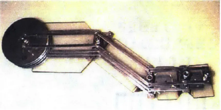
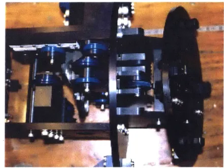
ac-Figure 2-2: Detailed view of the tail end of the Robotuna, showing the large peduncular link that supports the lateral keel mechanism.
curacy in the curvature of the nose is not as critical as the curvature of the main body [1]. The spacing of the joints decreases away from the nose and towards the tail, in a manner similar to Barrett's arbitrarily imposed "cosine rule" [1]. Near the caudal peduncle however, this cosine rule deviates and the spacing increases. This is effectively achieved by omitting the second to the last joint and producing a strong and massive peduncle, without compromising the flexibility of the tuna's undulatory motion. From a structural point of view, this modification is highly desirable be-cause it allows the strengthening of the skeleton at a very critical point. Moreover, it provides the necessary space for the installation of a fixed lateral keel.
Had the lateral keel been pivoted on a moving joint, its design would have been significantly more complicated and most likely would have affected negatively the smoothness of the outer surface.
In the early part of the design of the new Robotuna, the cable drive system of actuation was challenged by several other alternatives. The most important of these competitors included a hydraulic network and a bar-linkage system, the latter being conceptually similar to the one used to connect the wheels of old locomotives.
Hydraulic actuation provides compactness and strength, but introduces significant
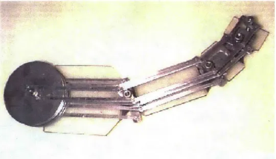
Figure 2-3: General view of the bar-linkage system, as it was conceived in the early stages of the design of the Robotuna.
complexity and cost that the designers were not willing to undertake. Furthermore, it reduces significantly the mechanical efficiency of the system, thereby requiring motors with larger power capabilities.
A bar-linkage inter-connection can offer three different but nonetheless significant
benefits: simplicity, linearity and perfect coupling. The simplicity stems from the fact that the system can be set up almost in its entirety by mechanically connect-ing only two types of buildconnect-ing blocks, aluminum pulleys and steel rods. By properly pinning the rods on the pulleys so that they are always arranged in parallel pairs, as shown in Figure 2-3, one can achieve perfect coupling of the joints. This means that the actuating motor of each joint can only affect the global orientation of the link directly attached to it. This is a highly desirable characteristic since it reduces significantly the overall angular error in the rear joints, and especially in the tail. In the opposite situation of perfect uncoupling, the total position error at a joint is the sum of the uncertainty of that joint and what is accumulated from all preceding ones. Evidently, even a small error of the order of one degree on each joint implies that the position of the tail can deviate by as much as five degrees, which is unac-ceptably high for our standards. Pure coupling resolves this problem and keeps the
total error within the uncertainty of each individual joint. Furthermore, this type of arrangement guarantees that the relation between the motor-drum's angle and the angle of each link referenced to a global fixed frame is perfectly linear. Linearity is very important because it greatly simplifies the position commands and presents a more accurate picture of the tuna's motion.
The bar-linkage inter-connection system however, is severely limited in four ways. Firstly, it introduces a great deal of frictional losses to the mechanism, by requiring ball bearings at each pinning location. Secondly, the bars are most likely to be weaker than steel cables and can potentially buckle when large compressive stresses are applied to them. Moreover, they are expected to undergo some twisting or bending deformation, thus affecting the accuracy of the mechanism. Finally, the most serious limitation rises from the fact that the tension applied to the bars can be shown to be inversely proportional to the cosine of the joint's absolute angle. This is necessary in order to keep the bar couples parallel to each other and preserve linearity and perfect coupling. Even though the relative angles of the links are not expected to exceed 30 degrees, the absolute angles could easily approach 90 degrees, thus increasing tensile and compressive stresses to dangerously high levels. This can be shown in Figure
2-3, where the last joint is nearly aligned to the previous one and yet the first couple
of bars that are associated with it experience high stresses.
The weight of these limitations pushed the design towards a cable-driven actuation system. The latter is conceptually closer to the tendon drive actuation used by real fish, and simultaneously offers simplicity, accessibility, low cost and high strength that cannot be surpassed by any of the other alternatives [1]. The arrangement of this cable drive system however, differs significantly from the one used in Barrett's tuna and attempts to adopt the benefits of the bar-linkage inter-connection, by imitating its main principle of operation.
2.2.2
Tendon Drive System
The particulars of the cable drive system will not be discussed in full detail. The interested reader may refer to Barrett's Master thesis for a more complete analysis
on this matter [1]. Instead, the discussion will be limited to three main "tricks" that have been employed to improve the actuation system according to the design goals specified in the previous section. These tricks are associated with an extended idler
pulley mechanism, a novel tail bar-linkage unit and an alternative compound pulley system.
Extended Idler Mechanism
An essential component of the cable drive transmission mechanism is the idler pulleys that hold the cables together and direct them to their paths. In the original Robotuna there was a particular type of idler pulleys, termed by Barrett as "conduit idler pulleys" [1]. They consisted of a set of overlapping discs that embraced the cables and arranged them neatly in parallel planes along the centerline of the tuna. The major benefit of this design was that it confined and protected all cable paths to the center. Moreover, it was intended to produce perfect decoupling of the joints. This however was not achieved in reality. Simple trigonometry can show that perfect decoupling can occur only in the limit as the conduit idlers have vanishingly small radius and infinite curvature. In essence, this would correspond to sharp corners in the cable lines along the joints. Unfortunately, cable-wear regulations require that the radius of curvature stays above a certain minimum, which depends on the cable thickness. Consequently, the conduit idlers could not be made arbitrarily small, and a finite amount of coupling was inevitable. To make matters worse, this type of coupling was found to be a very complex nonlinear function of the size of the driving pulleys and the range of travel, with a noticeable effect on the joint angles. For example, the arrangement of the last two joints in the old Robotuna can be shown in Figure 2-4 to produce an error of approximately 15% in the tail angle. This does not include the accumulated error from the previous joints.
A solution to this problem was found by considering the case of bar-linkage
ac-tuation. Instead of concentrating the cables to the centerline of the fish, large idler pulleys were used that wrapped the cables perimetrically around them and spread the cable lines outward, towards the sides of the hull. Figure 2-2 shows the driving
4U 35 30 125 ,20 15 10 5 0 5 10 15 20 25
Caudal Peduncle Angle in degrees
30 35
[ ctual
-da
Figure 2-4: Actual angular position of the tail joint as a function of the previous joint angle alone. The deviation from the dotted red line shows imperfect coupling.
pulley of the lateral keel and its first idler (half-hidden). The cables are completely exterior to the main skeleton and only interior to the ribs. Once again, trigonometry can easily show two remarkable benefits. Firstly, linearity is always preserved while always operating safely above the minimum radius of curvature. Secondly, the degree of coupling can be found to depend linearly on the relative size between the driving and idler pulleys, marked by R and r respectively in the simple relation shown below. In this relation, y represents the global (absolute) angle of the link, while 0 stands for the global angle of the preceding link. When the two radii are set equal, the joints are perfectly coupled and the motion of the link does not affect the orientation of the following ones in absolute coordinates. At the other (impractical) extreme, when the idler pulleys have a vanishingly small size, the fully decoupled condition is recovered.
A schematic demonstration of these two cases is shown in Figure 2-5.
r
For reasons of simplicity and reduction of error propagation to the latter joints, it was generally desired to keep the driving and idler pulleys at the same size. This
Position
osition
+ N, -I,
F---~~ITJ~*
'\~_~~/ ~ ~,>
I ~ -/
x
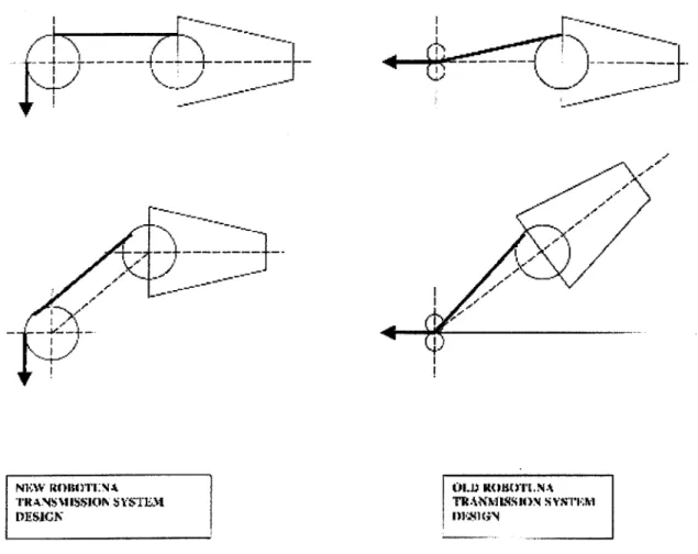
/ - \~-.----I / 7 Ii 4-I NEW ROROTI:N A TRANSMI.SSION SYSTEM DESIGN ODiJ R-OTLN A TRANMISSION ! YSTFMIN m.i41(NFigure 2-5: A schematic description of the fundamental difference in the idler pulley ar-rangement between the new and the old Robotuna. In the new Robotuna design, the rotation of a link leaves the orientation of the next link unaffected (perfect coupling). This is not the case with the old design, where the next link is expected to rotate by an equal amount (decoupling).
however was not always feasible, due to spatial limitations and cable stress consid-erations. Near the tail region, the cross-sectional area of the Robotuna decreases dramatically in order to comply with the slender and hydrodynamically fit shape of the fish. From a design perspective, packing all the necessary actuation and sensor components becomes a significant challenge. It may in fact appear to be tempting to keep the driving pulleys and idlers as small as possible. The consequence of this however is to increase the stress level at the cables, thus making cable compliance a real issue and a potential source of error. Different pulley sizes could yield more de-sirable solutions, and cost functions were constructed and optimized mathematically to investigate this possibility. These functions represented quadratic measures of the total angular error of a joint, which reflected the contribution of cable elongation and error accumulation from the previous (decoupled) joints.
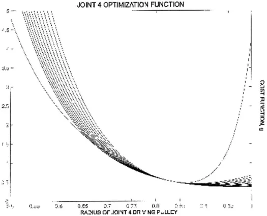
For instance, the cost function for joint 4 had the form:
f = (Aa)2 + (1 - r)2( o)2 R where T 2kR2 TO 2kR2
The constants 7, R, T0, RO represent the maximum torque loads and driving pulley
sizes relevant to the joint in question and the previous one. Figure 2-6 shows a plot of this cost function with the size of the driving-pulley for joint 4 (placed at the lateral keel). Different curves correspond to different driving-pulley sizes for the previous joint.
Tail bar-linkage unit
The area near the caudal peduncle of the tuna contains a feature which was given special attention. In biological terms, it is called "lateral keel" and represents a wide, disc shaped bony keel which extends horizontally along the sides of the fish[11] Its noticeable size and effect on the external geometry suggest that it might have
JOINT 4 OPTIMIZATION FUNCTION
RA')Us or ,1I1 T 4 DR V NG P.. LLCY
Figure 2-6: Cost function used for the minimization of the angular uncertainty in joint 4. a valuable hydrodynamic contribution, perhaps by reducing the added mass in the sway direction near the peduncle, and hence the power that is necessary to swing the tail. More importantly however, it is thought that its primary function is purely mechanical and provides a biological pulley mechanism that increases the contact angle between the great lateral tendons and the hypural plate, thereby increasing the amount of available torque (see Figure 2-7).[4]
The modeling of the lateral keel was very desirable when designing the new Robo-tuna, because it introduced some needed space and allowed for the possibility of further strengthening the tail. To accomplish the latter, nature was used again as a source of inspiration. A large driving pulley was located in the position of the lateral keel as shown in Figure 2-2, resulting in an increase in available torque, similar to the one described above. The location of this pulley was inconveniently far away from the tail foil however and required a 1.5 inch extension in the transmission. A bar linkage system of the type described in the previous section was the optimal candidate
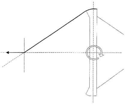
so-Figure 2-7: Side view of the lateral keel section in a real tuna. Courtesy of M.W.Westneat et al.[11] . Though the disc-shaped form is not clearly shown, the curving of the great lateral tendons (GLT) is obvious.
lution for this problem, primarily because it avoided the necessity of a separate loop of cables and guaranteed robustness and rigidity. Moreover, it saved some valuable space for the placement of position sensors and perhaps even for pressure sensors.
Each of the two bars of the system featured two sharp bends which are evident in Figure 2-2. These bends ensured that there would be no contact with the vertical tail shaft and thus helped to increase considerably the tail's range of motion. Despite their highly irregular shape however, they moved in parallel to each other as imposed
by coupling and linearity requirements. Their rectangular cross-section was optimized
to fit in the constricted geometry and provide very high axial and flexural rigidity. Finally, the bars were pinned to the large driving pulley and the tail connector (which was an equivalent hypural plate for the mechanical tuna) by means of minia-ture, double-sealed stainless ball bearings of low wear.
The overall caudal peduncle and tail mechanism resulted in a strong tail with minimal joint errors, which could be accurately controlled in a linear manner. This was an important step towards the development of a reliable Robotuna that can be used to investigate the details of fish-swimming. Ideally, position sensors would be necessary to identify precisely the exact orientation of the links and perhaps even to provide a closed loop control mechanism for perfect tracking. The placement of such sensors has been considered in the design and will be discussed later in more
Figure 2-8: Demonstration of perfect coupling principle in the case of a bar-linkage ac-tuation system. The rotation of the second link leaves the following links at the same orientation.
detail. Nevertheless, even without these sensors, visual observations and high thrust production measurements with the new Robotuna seem to indicate that the tail indeed performs as commanded.
Compound Pulley System
Another fundamental characteristic of the transmission design for the new Robotuna is related to the compound pulley system mechanisms that control the motion of the first two links. The idea behind a compound system was borrowed from Barrett's original tuna and is based on the need to reduce the torque required by the driving motors [2]. The first few joints are expected to withstand larger torques than the later joints, due to their relative distance from the tail foil, a fact which is particularly apparent in the old Robotuna design and has been verified by power measurements. The partial coupling of the new design alleviates some of the power requirement from the leading joints by distributing the load more uniformly between the motors, but is not sufficient to reduce the necessary torque to a satisfactorily low level. The latter however can be traded for a greater angular velocity requirement. This is a desirable step in order to comply with the specifications of the motors.
As in the original Robotuna, the compound systems consist of a combination of two pairs of pulleys that are fixed on different bulkheads. The effect is to reduce
Figure 2-9: Closeup view of the compound-pulley configuration as was implemented in the case of joint 1. A pair of blue pulleys is allowed to slide along the white delrin channel. In reality, this pair is cable connected to a second pair (not shown) axially located on the left joint. Finally, a short cable (not shown) connects the sliding pulleys to the side of the bulkhead of the right joint.
the cable tension by a factor of four and increase the angular velocity of the motor drums by the same factor. The idea behind this mechanism is very welcome, but the particular arrangement was plagued once again with nonlinearity at the joint angles. In fact, the rotation of the links relied on the stretching of small tensile springs connected at the ends of the cables. This type of transmission could not possibly yield accurate positioning. Its advantage however lay on the relative simplicity of its design.
As mentioned earlier, a fundamental principle in the design of the new Robotuna was to maximize the accuracy of the joint angles. It was thus clear that a more elabo-rate compound pulley system had to be developed. Quite naturally, the initial design efforts towards this issue attempted to produce a perfectly coupled compound pulley system that would adopt the design philosophy of the later joints. Unfortunately, it was impossible to incorporate the two together in a robust and reliable design. As a result, the opposite extreme was investigated. It was found indeed that the joints could be perfectly decoupled by positioning one end of the compound system at the center of the preceding bulkhead and by allowing the other end to translate freely in a diagonal direction. Attached to the second end was a short stainless-steel cable that connected it to the next bulkhead. The latter was rounded by means of removable aluminum ears to provide a linear angular relationship. Figure 2-9 is a closeup view of the compound-pulley system of joint 1 and shows the general arrangement.
This type of arrangement guaranteed perfect decoupling. By concentrating the two compound pulleys to the center of the previous joint, the overall system was oriented in a purely radial direction from the joint. Conceptually, the effect of this action would be similar to the effect of a pair of conduit idler pulleys with a vanishingly small radius, as shown in Figure 2-10 and Figure 2-11.
A small amount of partial coupling was admitted only to the system controlling
the first joint (joint 0). This "relaxation" in the design had to be made due to the lack of available space. More specifically, the positioning of the cable distribution system (mainly composed of tightly spaced fiddle pulleys) resulted in a small conflict with the compound pulley system and required the rerouting of a cable. This procedure slightly
I I V .1 I 21 -K7~
(I
-. I 7' 7, I 7 -7 77Figure 2-10: Schematic diagram of Compound Pulley System. The pulley at the left is fixed while the one diagonally to the right is allowed to slide, thus rotating the bulkhead that is attached to.
-- - - - - I --- - -- ---- 7 '7 7 7 .1~~I
Figure 2-11: Abstraction of the Compound Pulley system of Figure 2-10, showing the similarity to a perfectly decoupled transmission system.
compromised coupling and also introduced a small nonlinearity. Future designs should be wary of this problem and could attempt to resolve it.
From a design point of view, the proposed compound pulley mechanism was a risky solution to the problem of transmission, since it allowed for two pairs of freely translating pulleys (one pair for clockwise and one for anti-clockwise rotation). To secure the proper translation of these pulleys, it was decided that they should mounted on linear guides of stainless steel, that slid in appropriately shaped channels of delrin. Vibrational stability, proper alignment and wear constituted the main concerns of this decision. The results were quite satisfactory and eliminated the initial fears. Had it not been for space limitations and for friction considerations, one could even consider adopting this decoupled compound pulley system as the main principle behind the entire transmission design.
2.2.3
Reflections to the Transmission System Design
The transmission mechanism of the new Robotuna as described above can be clas-sified as a hybrid case. Even though it was based on cable-drive principles, it was flexible enough to incorporate a fundamentally different philosophy of a bar-linkage drive. Furthermore, the question of joint coupling in the links seems to be more in-volved: joints 0 and 1 are fully decoupled, joints 2 and 3 are fully coupled and joint 4 is partially coupled in a very specific way. At first, it may appear that all these optimization decisions have merely resulted in complicating the transmission system of the fish and have thus made the task of controlling the Robotuna unnecessarily dreadful. In fact, the opposite is true. The motion commands are almost perfectly linearly connected to the position outputs and, as a result, can be computed in a very straightforward manner. Moreover, there is significantly higher confidence over the actual position of the links without the use of position sensors, which reduces the need for active position tracking.
Figure 2-12: Overview of the final assembly of the new Robotuna, as designed in SolidWorks
2.3
Position Sensor Considerations
During the early stages of the design of the new Robotuna, it was considered prudent to allow for the possibility of active feedback position tracking on the joints. The importance of accurate positioning was stressed in a previous section and cannot be overemphasized. Thus, even though the new transmission mechanism is designed to reduce the need for a tracking system, the latter may appear to be increasingly valuable as the Robotuna ages. Indeed, corrosion effects, replacement of vital parts with slightly different ones, as well as possible changes in the skeleton in the long term could introduce uncertainty that would have to be eliminated only with feedback.
In the old Robotuna, position sensing was a task left entirely to the angular posi-tion encoders that were mounted directly on the driving motors. The major benefit of this type of measurement is the overall simplicity of installation. Safely above the water surface, the encoders can give accurate measurements of the commanded po-sitions of the rotors. Unfortunately, this is not sufficient to describe the actual joint angles, mostly due to complications arising from the dynamics of the compliant steel cables. A model can be constructed to account for these undesirable effects, but a more straightforward solution is sought instead which bypasses the cable dynamics and allows for collocated sensing on the joints.
The choice of the sensors was based on three necessary criteria: the sensors should be within one degree accurate, fully water-tight and sufficiently small to fit in a very constricted geometry. Microminiature DVRT type sensors were selected as the most desirable candidate. These are highly sensitive, state of the art linear displacement sensors that detect the differential change in reluctance caused by the motion of a miniature permeable core within two coil windings. They are about 1 inch long, water-tight, and have the ability to screen out thermal effects. Moreover, they have been used successfully in the hydraulically actuated Robotic Tuna that was built in Draper Laboratories.
Even though these sensors are linear, they were chosen over angular displacement measuring devices due to their exceptionally high sensitivity and reliability. This,
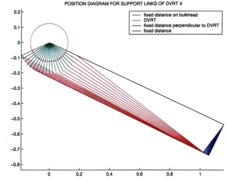
POSITION DIAGRAM FOR SUPPORT LINKS OF DVRT 4
0.2- - fixed distance on bulkhead
- DVRT
0.1 - fixed distance perpendicular to DVRT
-fixed distance 0--0.1 -0.2- -0.3- -0.4- -0.5- -0.6- -0.7--0.8 0 0.2 0.4 0.6 0.8 1
Figure 2-13: Schematic of the DVRT set up as it changes position with different angles. The purple circle designates the size of the bearing mounted on the relevant joint. The green segment describes a fixed distance from the center of the joint to the attached bulkhead. The DVRT is mounted on the red line (of variable length). The black and blue lines are legs of constant length, fixed or pinned to the rest of the mechanism.
of course, required that their mounting mechanism had to be designed carefully to convert linear to angular displacement. Naturally, one would desire a very simple and compact scheme that would be as linear as possible and that would not introduce any position error. Unexpectedly, this developed to an intricate optimization problem, where angular range, spatial constrains, sensitivity, linearity and monotonicity in the relation between linear and angular displacements, often played conflicting roles. As a consequence, the set up for each joint's sensor had to be different, to reflect the characteristics of the particular joint. In all cases however, the conversion from angular motion (of the joint) to the linear DVRT motion was achieved by means of a four-legged linkage system. Geometrically, this corresponded to a four sided structure with one variable angle and one variable length, as shown schematically in Figure 2-13. The installation of one of the DVRTs on the Robotuna is shown in Figure 2-15.
NONLINEAR MAP FROM LINEAR TO ANGULAR DISPLACEMENTS 0.4-Actual Function -Ideal Function 0.35- 0.3-WW 30.25- 3- 90.2-0 0.15 -0.1 -0.05 -0 10 20 30 40 50 60
RELATIVE ANGLE OF JOINT ROTATION FROM THE LEFT EXTREME, DEGREES
Figure 2-14: The purple line shows the functional relation between DVRT core dis-placement and joint rotation for joint 4. Extreme angle positions at 0 and 60 degrees (straight fish at 30 degrees). Monotonicity is preserved but not linearity, as the de-viation from the ideal red line shows. Sensitivity is also expected to be lost near the lower extreme.
Clearly, this was an inherently nonlinear model, but the parameters of the mecha-nism were chosen in such a way that the effect of the nonlinearity was reduced so that it was apparent only at extreme angles, close to or beyond the limits of the joint's allowable angular range. This effect is shown in Figure 2-14 for the DVRT of joint 4.
The position measuring system just described was the simplest solution to the problem of accurate sensing of the joint angles. So far though, in its four-month life, the Robotuna has operated without these sensors. This decision was made partly to simplify the task of preliminary testing and also to establish that the operation of the tuna was smooth and a typical swim would not be likely to threaten the extremely delicate and expensive DVRTs.
Finally, it can be stated with certain confidence that the ability to produce enough thrust for self propulsion is a good indicator that the compounded error of the joint
Figure 2-15: Closeup view of the DVRT placement for joint 4.
angles is sufficiently small for the preliminary tests that have been conducted, and therefore position sensors are not yet critical for operation.
2.4
External Shape Design Considerations
2.4.1
Relevance of the Problem
To perform a detailed study of the dynamics of fish swimming, it is essential that the Robotuna must resemble an actual fish as closely as possible. This suggests that apart from the obvious need for a smooth, periodic undulation, it is important to replicate accurately the external characteristics of its shape. The metallic skeleton structure is not an acceptable imitation of a tuna's body. In fact, it is hardly any different from a typical, five-link robotic arm and resembles a fish form only in the most stylistically abstract way. The task of camouphlaging this mechanical assembly of links and pulleys to a convincing bluefin tuna form is precisely the main concern
behind the rib and skin design. The weight of this design task was undertaken by senior undergraduate student, Michael Jakuba[7]. For this reason, I limit myself to an outline of the main concerns of the design and a brief description of the solutions that were adopted.
2.4.2
Design Concerns over the Skin and Ribs
Barrett's solution to the issue of a smooth thunniform shape provided for a thick layer of skin that lay over a system of ribs and foam. The skin was a composite of lycra, latex and foam layers. The lycra served to reduce small irregularities in the foam and was used as the outer layer. The purpose of the foam was to average larger irregularities and to eliminate any bumps caused by the ribs during the flexing of the body, an effect frequently described as the "hungry dog" look. Finally, the latex sheets strengthened the stiffness of the skin and assured that it was tightly wrapped around the body at all times. Underneath this complex skin there was a section of thick "flesh" and "bones", trimmed appropriately to resemble the shape of a tuna. The "flesh" was composed of highly porous foam segments, separated transversely by plastic ribs that were fixed on a common spine. This system conveniently filled the space between the metallic skeleton and the composite skin, and served two important functions. Firstly, it generated the general shape of the tuna by allowing the skin to contact it. Secondly, it provided an energy storage mechanism, by compressing like a spring at large joint angles and then releasing this elastic potential in the form of useful kinetic energy, thus reducing the required peak amplitude of the input power of the motors.
On the negative side, this type of massive flesh reduced the amount of available space within the fish's body. Furthermore, it caused some difficulties near the tail section, where the cross-sectional area of the outer hull was only slightly larger than the enclosed peduncle, leaving little space for flesh and skin. Moreover, it reversed the advantage of energy storage by inducing major power losses. These losses were primarily due to a cyclic pumping effect of the entrained fluid, caused by the con-traction and release of the foam. As the fish aged, the elastic properties of the foam
deteriorated and its structural damping increased, thus leading to even higher levels of power losses. Finally, another disadvantage of this particular flesh design was the difficulty and time involved in its installation and removal, which were necessary in order to expose the skeleton. This is often necessary for inspection and maintenance reasons. As a consequence, it was highly desired to construct a rib and skin design that was more readily removable and did not require hours spent on removing and re-attaching each and every rib and foam segment.
2.4.3
Design Solutions on Skin and Ribs
The design scheme of the new Robotuna was fundamentally different from what was described above. Instead of large, disc-shaped rib structures surrounded by foam, a peripheral rib cage was used, very similar to the one used in Kumph's Robopike
[8]. More specifically, the ribs took the form of thin, metallic rings, spaced closely
together and connected axially by means of two flexible splines that are pivoted to the joints in a way that guarantees smoothness in the swimming profile. A side view of this assembly is shown in Figure 2-16. These rings define the desired thunniform shape and provide a rigid surface where the outer skin can attach, far away from the robotic skeleton. The issue of flesh is avoided completely, resulting in a very light overall structure that does not interfere significantly with the mechanical links of the core and that conveniently leaves plenty of "empty space" to be occupied by pressure sensor gear. A more detailed description of this will follow in a later chapter.
More importantly, this peripheral cage-like rib structure can be removed and re-installed with minimal effort, almost like a sock. It also allows for the possibility of installing alternative fish shapes to the same skeleton, if so desired in the future. To avoid a hungry dog look, the ribs are coated with a thick layer of overlapping scales. These scales bear little resemblance to what is found in actual fish, but have been designed to play a similar role. They are composed of very thin, 3inch-by-1/2inch pieces of vinyl and have been pinned permanently to the outer surface of the ribs. As they overlap each other, they create a very smooth surface that can be easily stretched and contracted and that allows for low water permeability. It is indeed a very elegant
Figure 2-16: General view of the spine and rib design.
solution to the issue of external smoothness, developed by Jakuba. Finally, despite the fact that the pinning of the scales on the rib surfaces was a very time intensive exercise (there are more than 1000 scales currently pinned on the outer structure of the tuna hull) it was a very desirable technique in the long run, since the pinning was meant to be permanent.
Exterior to the scales lay the outer skin in a way that resembles the skin/scale formation in real tunas. Unlike Barrett's composite skin, the new one involved only a thin layer of lycra. The addition of a foam layer was deemed unnecessary, since the hungry dog look was sufficiently reduced by the scales underneath. Also, the latex stiffening layer was eliminated as it was impractical: latex has been found to lose some of its elastic properties with time, when exposed to highly chlorinated water, and can easily tear catastrophically. Moreover, the omission of foam reduced its importance, as there was no special concern over tightness.
As was proven very early on, this thin and light outer skin structure resting on a mesh of overlapping scales resulted in an exceptionally smooth external fish profile, very suitable for laser based visualization techniques, such as DPIV.
A sole notable disadvantage of the scale structure is that it introduces significant
power losses, mainly as Coulomb and linear friction between the individual scales. From a design point of view, one only has to consider that the new tuna has more M
than a thousand moving parts, each making its own contribution to the overall losses. The power losses to the skin have been measured to be of the order of 30% of the total frictional losses of the mechanism. This, of course, is an issue of significant concern, but steps have been taken to cancel out the effect. An analytical description will follow in the next chapter. Nevertheless, it is worthy to remark at this point that the largest contribution of the scale losses does not come from scale-to-scale interactions as might have been expected, but from the contact between scales and the thin silicone elastic bands that are used to keep them in an orderly manner[7]. A better choice for these bands could perhaps make a marked difference in the power consumption.
2.4.4
Nosecone Design
The design of the front section of the fish was also an issue of some concern. In compliance with the old Robotuna, a rigid nosecone shell, 8 inches in length, was attached to the first bulkhead of the mechanism. As described earlier, this bulkhead has the capability of performing an anticlastic motion defined by the first joint (joint
0).
The shape of the nosecone shell was measured in vertical segments from the cast of a real bluefin tuna. To a good approximation, it can be described as a collection of elliptical cross-sections, with varying eccentricities. Having determined the shape, a wooden model was developed and then used to thermophorm a 1/8" PVC layer. Figure 2-17 shows the actual wooden model with a thermoformed layer. For reasons of external rigidity, the shell was subsequently re-enforced with an inner elliptical bulkhead of aluminum, as well as with a thin layer of epoxy.
A major improvement over the nosecone of the old Robotuna and a subject of
particular emphasis was the transition from the rigid cone to the first bulkhead and the flexible rib structure behind it. This occurs only 8" away from the tip of the fish. Evidently, the Reynolds number at that location is not fully turbulent for all possible operating speeds. Consequently, if the transition is characterized by large gaps or extrusions, it is possible for the flow to separate, especially since turbulence
Figure 2-17: Wooden nose model and actual nosecone, thermoformed from a square PVC sheet
may not be present to stabilize the boundary layer. Such a disturbance in the flow may contribute significantly to the total drag and, more importantly, may disrupt any possible vorticity control mechanism employed by the tuna for efficient propulsion. In fact, the nosecone transition was so poor in the old Robotuna, that a silicon collar had to be placed as an easy, but temporary and inelegant, solution[16].
The Robotuna design solved the transition problem permanently and elegantly in three ways. First of all, it provided for two pairs of mounting blocks that were attached to the inner part of the first bulkhead and served as anchors for four plastic tubular springs residing inside the nosecone. This design solution was offered by David Beal and avoided completely the need for external connections. The spring-loaded cone was then capable of maintaining a fixed position with respect to the bulkhead during swimming. Secondly, a ring of scales was attached to the end of the nosecone, thus making the rest of the body a natural extension of the cone[7]. Finally, the nosecone was allowed to be covered completely by the thin lycra skin, thus creating

![Figure 2-7: Side view of the lateral keel section in a real tuna. Courtesy of M.W.Westneat et al.[11]](https://thumb-eu.123doks.com/thumbv2/123doknet/14681745.559412/26.918.119.511.95.325/figure-view-lateral-keel-section-real-courtesy-westneat.webp)