HAL Id: hal-01396857
https://hal.archives-ouvertes.fr/hal-01396857
Submitted on 15 Nov 2016
HAL is a multi-disciplinary open access
archive for the deposit and dissemination of
sci-entific research documents, whether they are
pub-lished or not. The documents may come from
teaching and research institutions in France or
abroad, or from public or private research centers.
L’archive ouverte pluridisciplinaire HAL, est
destinée au dépôt et à la diffusion de documents
scientifiques de niveau recherche, publiés ou non,
émanant des établissements d’enseignement et de
recherche français ou étrangers, des laboratoires
publics ou privés.
Wireless Pressure Measurement in Air Blast using
PVDF sensors
Jérémie Fourmann, Anthony Coustou, Hervé Aubert, Patrick Pons, J Luc, A
Lefrançois, A Lavayssière, A Osmont
To cite this version:
Jérémie Fourmann, Anthony Coustou, Hervé Aubert, Patrick Pons, J Luc, et al.. Wireless Pressure
Measurement in Air Blast using PVDF sensors. IEEE Sensors, Oct 2016, Orlando, United States.
�hal-01396857�
Wireless Pressure Measurement in Air Blast
using PVDF sensors
J. Fourmann1,2,3, A. Coustou1,2, H. Aubert1,2, P. Pons1,2, J. Luc3, A. Lefrançois3, M. Lavayssière3, A. Osmont3 1 CNRS, LAAS, 7 Avenue du colonel Roche, F-31400 Toulouse, France
2 Université de Toulouse, LAAS-CNRS, F-31400 Toulouse, France 3 CEA, DAM, GRAMAT, BP80200, F-46500 Gramat, France
Abstract - This paper presents a wireless dynamic
measurement of the air blast overpressure. This system is based on a piezoelectric PolyVinyliDene Fluoride
(PVDF) sensor fully characterized with the help of a shock tube calibration instrument. A dedicated optimized wireless system is used in order to transmit the transient pressure. The pressure signal inside a fire ball was recorded wirelessly for the first time during the open field detonation of an explosive. The proposed simple and low-cost technique allows transmitting high bandwidth pressure signal and could be an alternative to the conventional wired transmission setup.
Keywords - wireless sensors, pressure measurement, air blast experiment.
I. INTRODUCTION
To characterize the signature of an explosion, the transient pressure event is one of the key inputs. The accuracy of the analytical predictive blast wave model is highly dependent on the measurement. The pressure at a given location during an explosion typically presents very fast transient with short time rise (<< 1 µs), large bandwidth between 100 Hz and 1 MHz and high pressure level (> 10 MPa) in high-temperature environment (> 1000 °C) [1][2]. These extreme conditions make the real-time measurement of the air blast pressure very challenging and many issues must be addressed. First of all the finite bandwidth and resonant frequency of available pressure sensors may generate some undesired spurious harmonic distortion on the measured signal. In order to overcome this issue, methods are investigated to calibrate the sensors and to improve the reliability of the pressure measurement [3][4]. The shock tube calibration technique is used here to determine the transfer function of pressure sensors and to derive from such function the resonant frequency, low and high cut-off frequencies [4]. Moreover, during the air blast experiment long cable are often used to connect the sensor to the acquisition unit. Due to the series resistor (~10 mΩ/m) and shunt
capacitor (~100 pF/m) of such long transmission lines (e.g., 60 meters of RG58 coaxial cables) the 3 dB-bandwidth of the wired transmission channel does not exceed typically few tens of MHz. This bandwidth
limitation makes the conventional wired technique unsuitable to transmit data from next generation of ultra-wideband (> 1 GHz) pressure sensors. Today these issues are not solved and make the air blast pressure measurement difficult.
The paper proposes a complete overview for an alternative solution using the wireless transmission of pressure signal through the fire ball during an air blast experiment. The paper is organized as follows. In Section II the pressure sensor is calibrated from a shock tube technique. Key performance descriptors of the sensor are derived from its measured transfer function. In Section III a complete description of the proposed wireless system is presented. Finally the air blast experiment is described and the measurement results are discussed.
II. SYSTEM ANALYSIS AND CALIBRATION
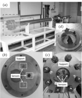
The sensor used here is the M60 PVDF piezo-electric film provided by Müller Instrument Company [5]. This sensor allows achieving a measured sensitivity of 3 pC/bar and a bandwidth of 1 MHz. It requires an appropriate conditioning electronics in order to convert the charges generated in the transducer into a measurable voltage. The shock tube is used to calibrate this pressure sensor. From the generation of a step pressure signal with tens of nanosecond rise time, different pressure sensors can be calibrated over the MHz range. A shock tube is a tube with a diaphragm which separates two chambers (driver and driven gas) at different pressures. When the diaphragm is burst at a given pressure (Fig 1(d)), it creates a shock wave propagating through the tube. For the experiment, a shock tube was provided by the CEA Gramat (see Fig. 1(a)) [6]. The facility can produce sustained reflective shock waves from 0.1 MPa up to 7 MPa during few microseconds. For that purpose, the sensors are mounted on the end steel plate of the tube (Fig 1(b)-(c)). The calibration technique consists of measuring the response of the sensor compared to a reference sensor [4]. In our case, the theoretical reflective overpressure is 21 bar using the operational conditions shows in the Table 1.
Fig. 1. (a) Shock tube, (b) Mounted sensors, (c) Sensors installation and (d) Burst diaphragm
Table. 1. Operational conditions of the shock tube calibration experiment
Driver gas Nitrogen Driver gas initial pressure 64.5 bar Driver gas initial temperature 94.5 °C
Driver gas Air
Driven gas initial pressure 0.98 bar Driven gas initial temperature 23.5 °C
Figure 2(a) is a zoom on the transient during the first reflective shock wave. As given in the datasheet [5], a measured rise time of 100 ns for the proposed PVDF sensor can be obtained. The stationary mean pressure is measured at 21 bar ± 1%. Based on this transient response, the transfer function of the sensor is computed (see Fig. 2(b)). The resonant frequency of the sensor is 3.6 MHz and the sensor bandwidth (-3 dB) is around 1 MHz. The developed measurement system consists in using a calibrated piezoelectric PVDF Muller M60 sensor with a dedicated wireless transmission. The wireless setup reported here is composed of transmitter and receiver units operating at 6 GHz with 100 MHz bandwidth (see Fig. 3). During the experiment, the transmitter unit converts the output voltage of the piezoelectric sensor into a frequency shift with the voltage controlled oscillator (VCO). The resulting frequency modulated (FM) signal is transmitted to the receiver unit through the fireball. The received FM signal is filtered and amplified by the receiver unit. The intermediate frequency (IF) is obtained by mixing the received modulated signal with the stable sinusoidal signal generated by a 6 GHz Local Oscillator (LO).
Fig. 2. M60 overpressure sensor response in a shock tube to a reflective pressure step: (a) M60 sensor transient and (b) derived from the measured transfer function of the sensor
The frequency demodulation process applied to the IF signal is performed numerically by using the classical
Short-Time Fourier Transform (STFT). The -3 dB bandwidth of the wireless system is 100 MHz. It is large enough for transmitting the measurement signal which its bandwidth is mainly limited by the dynamic performance of the sensor transduction.
Fig. 3. Block diagram of the wireless sensor system: (a) transmitter unit and (b) receiver unit
III. MEASUREMENT RESULTS AND DISCUSSION
The sensing device is located at 1 meter of a 1 kg of RDX/HTPB 85/15 high explosive ball. A horn antenna is used to receive the signal. Acquisition
units and the experimental team are in a safe place. An ultra-fast v2511 Phantom camera is used in order to record the video of the explosion shown in Fig. 4. The pressure signal at the sensor’s output is wirelessly transmitted in real time to the acquisition unit and simultaneously transmitted through a 60 meters coaxial cable for comparison purpose.
Figure 4: Different steps of the fireball during the air blast experiment: (a) t = 1.0 ms; (b) t = 3.3 ms; (c) t = 9.6 ms; (d) t = 20.0 ms
The received FM-modulated signal is shown in Fig. 5(a). This signal is processed in order to extract the pressure signal displayed on Fig. 5(b). Although the time-variation of the wirelessly transmitted signal looks very erratic, the FM demodulation allows recovering the embedded overpressure signal.
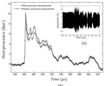
Fig. 5. (a) Received FM-modulated signal vs time and (b) Measured overpressure signal during the experiment using the wireless and conventional wired links
As shown in Fig. 5 the derived pressure signal is in good agreement with one obtained from the conventional wired transmission. The difference between the two measured peak static overpressures does not exceed 200 mbar and it may be explained by the presence of the measurement cable. The peak static overpressure is found to be 10 bar ± 1%. Moreover a rise time around 1 µs is observed, as expected. Due to the low cut-off frequency of the sensor, the relaxation of the pressure signal is shorter than expected.
IV. CONCLUSION
A complete solution for the wireless measurement of the air blast overpressure is proposed and experimentally validated in this paper. A shock tube was used to calibrate the pressure sensor and the designed wireless system has been placed inside a fireball during an air blast experiment. The peak static overpressure has been successfully recorded. This solution is an interesting alternative to wired transmission techniques as ultra-wideband (> 1 GHz) pressure sensors will be available in the future. Works are now focusing on the development of a complete, optimized and integrated sensors network and on the real time temperature compensation of the VCO sensitivity.
ACKNOWLEDGEMENTS
The authors thank Fabrice Mathieu for its help during the development of the high bandwidth sensor conditioner and the Region Languedoc Roussillon
Midi-Pyrénées for its contribution to the financial
support of this work.
REFERENCES
[1] W. Fickett, C. William, “Detonation: Theory and Experiment”, Dover Publications, 2011.
[2] P.-L.Walter, “Air-blast and the Science of Dynamic Pressure Measurements,” Sound and Vibration, pp. 10-16, December 2004.
[3] C. Bartoli, M. F. Beug, T. Bruns, C. Elster, T. Esward, L. Klaus, A. Knott, M. Kobusch, S. Saxholm, C. Schlegel, “Traceable dynamic measurement of mechanical quantities: objectives and first results of this european project,” Int. J.
Metrol. Qual. Eng., vol. 3, n°. 3, pp. 127–135, May 2013.
[4] C. Matthews, F. Pennecchi, S. Eichstädt, a Malengo, T. Esward, I. Smith, C. Elster, A. Knott, F. Arrhén, A. Lakka, “Mathematical modelling to support traceable dynamic calibration of pressure sensors,” Metrologia, vol. 51, n°. 3, pp. 326–338, June 2014.
[5] Müller instuments,”Pressure Transducers M60”, datasheet, 2016.
[6] J. Luc, J.M. Bouvet, B. Miossec, “Estimation de l’incertitude d’étalonnage de capteurs de pression dynamique,”15th International Metrology Congress, Paris, France, October
![[PDF] Formation PrestaShop : Module TNT Express | Formation à télécharger en PDF](data:image/gif;base64,R0lGODlhAQABAIAAAP///wAAACH5BAEAAAAALAAAAAABAAEAAAICRAEAOw==)