HAL Id: hal-02415474
https://hal.archives-ouvertes.fr/hal-02415474
Submitted on 17 Dec 2019HAL is a multi-disciplinary open access archive for the deposit and dissemination of sci-entific research documents, whether they are pub-lished or not. The documents may come from teaching and research institutions in France or abroad, or from public or private research centers.
L’archive ouverte pluridisciplinaire HAL, est destinée au dépôt et à la diffusion de documents scientifiques de niveau recherche, publiés ou non, émanant des établissements d’enseignement et de recherche français ou étrangers, des laboratoires publics ou privés.
development of a dosage system for the incineration of
radioactive and particle-laden liquid
S. François, F. Lemont, R. Magnin
To cite this version:
S. François, F. Lemont, R. Magnin. development of a dosage system for the incineration of radioactive and particle-laden liquid. Waste Management, Mar 2018, Phoenix, United States. �hal-02415474�
DEVELOPMENT OF A DOSAGE SYSTEM FOR THE INCINERATION OF RADIOACTIVE AND PARTICLE-LADEN LIQUID
Sébastien François, Florent Lemont, Rodolphe Magnin CEA-DEN-DE2D-SEVT-LPTI – F30207 Bagnols sur Cèze France
ABSTRACT
Large amounts of Ionic Exchange Resins (IER) waiting for treatment are stored on nuclear sites. In order to find an outlet
The alpha incinerator has been operating since 1999 at the CEA Valduc center in France for the treatment of alpha-bearing technological waste. The fact that the incinerator has been working smoothly for 18 years and the experience gained during this period indicate that it can also be used to treat other types of waste, such as Ion-Exchange Resin (IER) suspensions. The aims of an R&D project initiated in 2014 were to develop a dosage system allowing these suspensions to be injected into the heart of the treatment system and to evaluate the performance of the incinerator when these materials are added to technological waste.
This article describes the work carried out to develop a dosage system for heavily particle-laden fluids (with more than 50 vol% solid particles), with the aim of delivering waste continuously into the treatment furnace. The proposed device consists of a feeding tank equipped with a stirrer, a piston pump, and a pneumatic transport system. Reliability has been improved by replacing the initial sealing system (a piston with seals), by a very tight (~4 µm gap), therefore sealless, sleeve/piston unit. Adjusting the carrying gas flow has optimized the system as a whole, making it safer and more robust.
The system has been qualified through more than 1000 hours of operation and the results obtained for the incineration of IER suspensions suggest that industrial transport is feasible and will thus begin soon.
THE IRIS PROCESS
The IRIS process was developed to meet very specific requirements. It enables alpha-contaminated and highly chlorinated (25 wt% chlorine) plastic waste to be incinerated at a rate of several kilograms per hour [1]. No acceptable solutions meeting these constraints could be developed with existing technologies. The innovative incineration process developed for this purpose can be broken down into three steps: waste preparation, thermal treatment (i.e. incineration per se) and off-gas treatment.
The first step involves waste preparation to allow metering of a continuous feed stream to the incinerator. It includes detection of scrap metal (which could damage process equipment), sorting, grinding, buffer storage and continuous metering of the incoming material.
The thermal treatment is a two-step process as illustrated in Figure 1. The waste is first pyrolyzed at 550°C in an electrically heated rotating kiln with argon scavenging, although a small quantity of air is injected to prevent the formation of undesirable tars. The resulting solid carbonized residue, or pitch, still contains 80% of the carbon and inorganic matter initially present in the waste.
Pyrolysis furnace
(550°C)
Pitch
Calcination furnace
(900°C)
Ashes
Afterburner
(1100°C)
Gas processing
Organic waste
(4 kg/h)
Figure 1. IRIS thermal treatment process
The pitch is then calcined online in a second electrically heated rotating kiln at 900°C in excess oxygen. After a two-hour residence time, the process yields very high quality ashes (with less than 1% residual carbon content) that are compatible with radionuclide recovery or vitrification processes at the discretion of the plant operator.
The pyrolyzer and calciner off-gas streams are transferred to an afterburner operating at 1100°C in excess air before entering the off-gas processing system. This specific treatment complies with the gaseous emission standards of the European Commission draft directive on industrial incineration of hazardous waste, including dioxins and furans.
The off-gases are driven toward a gas treatment facility (not discribed in figure 1) gathering cooler, prefiltration system, HEPA filter and scrubber.
ADAPTATION OF THE FEEDING SYSTEM
The IER that have to be incinerated are stored under nitric acid 0.5N solution in 5L container as represented in figure 2.
Figure 2. IER stored under nitric aqueous solution in 5L container
The feeding hooper used for the introduction of crushed organic waste can not be used for the IER for two main reasons :
- The IER have to remain submerged because of safety reasons
- The IER do clog rapidly the hooper used for organic technological waste introduction
A new device with adapted design has been proposed and test in recent years. It is described in figure 3.
Figure 3. Specific device for IER feeding
Stirred hooper
Valve
Gas Injection
Valve Piston + Motor Gas
The feeding device involved :
- A glass hooper containing the resins submerged into the nitric aqueous nitric solution - A stirrer able to work at different stirring rate
- A piston pump
This feeding device is connected to pipe driving the IER up to the pyrolysis furnace as described in figure 4.
Figure 4 : IER feedind systemconnected to the pyrolysis furnace
The carrier gas help the IER driving in the pipe while avoiding untimely decantation. Preliminary researches never published have shown that the volumic ratio between IER and solution is essential in order to ensure a constant composition mixture feeding. This ratio is around 60 vol%. If the initial ratio is above this limite, the IER become drained in the hooper what is not consistent with safety requirements. If the initial ratio is below this limit, the hooper become full of water leading to thermal disturbances in the furnace.
As shown in figure 4, the IER are fed together with technological waste in the pyrolysor where their treatment begins.
WASTE COMPOSITION AND OPERATING MODE
Several tests have demonstrated that the treatment of pure IER is not possible in the IRIS facility because of water management and chemical compatibility with a rotary kiln technology. Thus, the IER have to be mixed with organic waste having a composition likely to change but by the percentage indicated in table 1.
The IER are LEWATIT MP made of polystyrene cross-linked with di-vinylbenzene fitted with quaternary amonium. Glove box
CARRIER GAS
ACTUATOR
IER + Water Beaker Valve IEROther organic waste
Coumpound Composition (Wt%) Coton + cellulosic paper 10.0 ± 5
Latex + Neopren ≤ 34.0
PE + PP + EVA ≤ 20
White PVC ≥ 24.0
Pink PVC 12.0
Table 1 : Composition of organic technological waste
Préliminary test performed with different percentage of REI in the waste have demonstrated that the optimum is around 20%. Above this limit, the temperature become erratic in the pyrolysor what is related to thick deposits appearing in the kiln. In this case, the ashes quality is not consistent with the requirement of a carbon content remaining under 1wt%. Under this limit, the total treatment time of all the stored IER may become too long.
Then, in the final assessment tests, the final global feeding rate was : Technological waste (Composition table 1) : 2.8kg.h-1
IER : 0.850kg.h-1
The total feeding rate is then 3.650kg.h-1
The experimetal facility into which the experiments have been carried out was design to operate continuously with a feeding rate of 5kg.h-1. The industrial plant implemented at the Valduc center has been design for a feeding rate of 7kg.h-1 [2]
Following some changes in the past years, the operating mode has become limited to 6 hours of incineration per day. Thus, the test have been adapted to this news mode to be the most representative.
RESULTS
The first result is a perfect working of the feeding device with a IER content of 60vol%. More than 1000 hours of working have been validated without any dysfonction. The most important was then to study what is going on regarding the process working when IER were introduced.
The logging of operating data in pyrolysor and calcinator have shown some temperature instability but remaining relatively in the normal operating range (500°C up to 600°C for the pyrolysor and 800°C up to 900°C for the calcinator). 3 tests of 6 hours were performed. Between each of them, the temperature of the furnaces were maintained at the working level.
The figure 5 depicts the temperature evolution in the pyrolysor when the figure 6 depicts those of the calcinator. The
These results show :
- The temperature remain stable in the pyrolysor exept in the second zone where they increase each time up to 590°C
- When the organics feedings are stopped, all the temperatures come back to their initial level
- The power injected in zone II plunges at level zero what is consistent with the temperature increasing. This proves that heat is released in the zone II because of oxydation reaction
- The temperature in calcinator remain almost stable. However, some pics are appearing in zone I and II.
Figure 5 : Evolution of temperature in Pyrolysor Test n°1 Test n°2 Test n°3
Te m pe ra tur e (° C) P ow er (W ) Z1 Z2 Z3 Furnace zones POWER TEMP
Figure 6 : Evolution of temperature in Calcinator
Temperature instabilities seem to be related to pitch agglomeration that could be linked to water vaporisation in Zone I. Indeed, some aggregates have been found during samplings taken from the pipe connecting pyrolysor and calcinator. The figure 7 provides a picture of these centimetric aggregates.
Figure 7 : Aggregates sampled from the pitch
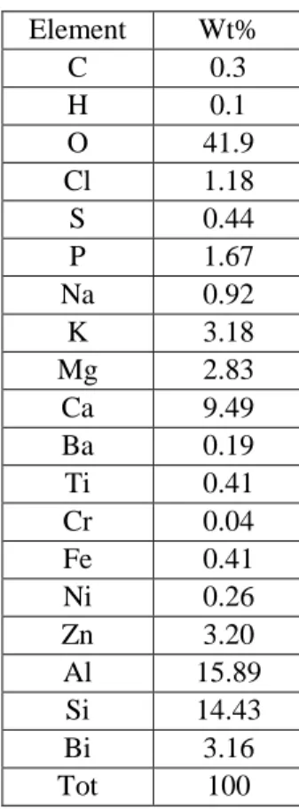
The presence of the aggregates has no effect on the quality of the ashes. The table 2 gives the composition of the ashes into which the carbon is under 0.5%.
Te m p er at u re (° C) P ow er (W ) POWER TEMP
Test n°1 Test n°2 Test n°3
Date - Hour P ow er (W ) Z1 Z2 Z3 Furnace zones
Element Wt% C 0.3 H 0.1 O 41.9 Cl 1.18 S 0.44 P 1.67 Na 0.92 K 3.18 Mg 2.83 Ca 9.49 Ba 0.19 Ti 0.41 Cr 0.04 Fe 0.41 Ni 0.26 Zn 3.20 Al 15.89 Si 14.43 Bi 3.16 Tot 100
Table 2 : Composition of the ashes
These results shows that introduction of IER together with organic technological waste has a sensible effect on the temperatures recorded in the different furnaces of the process. This is directly related to aggregates formation in the pyrolysor that has no effect if the IER content does not exceed 22% of the weight of the waste. Furthermore, as it can be read in table 2, the presence of aggregates dropping in the calcinator has no effect on the quality of the ashes since their carbon content remain under 1%. It is also worth noting that the ashes composition is suitable for a potential vitrification.
Finally, the operating mode used for this test is positive because it leads to a periodical return of the temperature to their initial level. This is consistent with the results obtained with the studies performed to propose the sequencing of the waste feed stream in the process [3]
CONCLUSION
The results presented in this paper illustrate the opportunity to use existing thermal treatment facility to process waste not initially concerned. The case of IER is of importance because some of them have to be destroyed rather than being cemented.
The use of IRIS process has seemed interesting because of its ability to transform organic waste into ashes having very low carbon content. This is why a specific feeding device has been design and built with positive results for introducing IER alongside organic waste (but not mixed with them).
If the results are satisfactory, they also have shown that IER adding has a sensible effect on the process and essentially on the monitored temperature in the furnaces. This is due to the formation aggregates in the pyrolysor furnace that has no effect on the process efficiency on condition that the amount of IER in the waste does not exceed 22%. If this condition is met, the incineration of IER together with other organic waste in the IRIS process is actually feasible.
REFERENCE
[1] A. Jouan, J.P. Moncouyoux, R. Boen, R. Cartier, J.J. Vincent and T. Longuet, “Incineration Processes for Radioactive Waste with High Alpha Contamination: New Developments”. IT3 Conference pp. 209-210, May 8-12, 1995, Bellevue, Washington, USA.
[2] H. Chateauvieux, P. Guiberteau, Th.Longuet, M.Lorich, The Iris incinerator at CEA-Valduc assessment after one year of active waste incineration, WM’00 Conference, February 27 - March 2, 2000, Tucson
[3] F.Lemort, J.P.Charvillat. Improvement of the IRIS process for incineration of various radioactive waste composition. WM’03 Conference, February 23-27, 2003, Tucson, AZ