3rd International Conference on Bio-Based Building Materials June 26th - 28th 2019
Belfast, UK
ID_ DD281
TOWARDS FIELD-ORIENTED TESTS TO EVALUATE THE WORKABILITY AND
COHESION OF EARTH SLIPS FOR BUILDING APPLICATIONS
T. Vinceslas1, T. Lecompte 1*, H. Lenormand2, A. Hellouin de Menibus3,4, E. Hamard5, T. Colinart1,
1- Univ. Bretagne Sud, UMR CNRS 6027, IRDL, 56100 Lorient, France 2- UniLaSalle, 3 rue du tronquet, 76134 Mont-Saint-Aignan, France
3- Eco-Pertica, Hôtel Buissonnet, 61340 Perche-en-Nocé, France
4- Association Nationale Des Chanvriers en Circuits Courts, 30610 St Nazaire des Gardies, France
5- IFSTTAR, MAST, GPEM, 44344 Bouguenais, France *Corresponding author; e-mail: theo.vinceslas@univ-ubs.fr
Abstract
Hemp-clay concrete for building thermal insulation can be made of earth available on-site, obtained from earthworks or ancient clay building deconstruction. Craftsmen evaluate qualitatively the slip binding capacity in order to optimize and control the formulation with simple field oriented tests. There is a need for scientific works to understand the rheological behavior of clay slips depending on all the parameters that can vary on-site, such as the water to clay ratio, the clay activity, the particle size distribution. This knowledge would allow to define quantitative field-oriented tests that can be used on-site by craftsmen.
In this study, the variability of 27 earths was first assessed through a simple qualitative test to identify their behavior at different water levels, and conventional geotechnical identification tests. Slips behave as non-Newtonian fluids, with an apparent yield stress 𝜏0 and a shear rate dependent
viscosity. These two characteristics help to quantify the slip cohesion. Both yield stress and viscosity of slips with different earths were studied thanks to a vane-geometry rheometer and a simple test, developed for this study, which could be used on-site: the plate test. The results allow to assess the validity of this test to identify the yield stress level.
Keywords:
Earth material, rheological behaviour, yield stress, field oriented experiments, light earth
1 INTRODUCTION
Earth construction has been regained awareness for the recent years, especially due to its low environmental impact (Azeredo, Morel, and Lamarque 2008; Bui et al. 2009; Moevus et al. 2016; Aubert et al. 2015). This material has been used for centuries and the know-hows about it are very ancient, adapted to local knowledge. The material workability in the fresh state must be controlled to aim some hygro-thermal and mechanical characteristics in the hardened state. Furthermore, a minimum of cohesion into the earth granular packing will allow the setting and the self-bearing of the wall or render. The rheological behavior of the earth can also orient the choice of the construction process. However, only few works deal with the rheological behavior of the earth material for construction (Azeredo, Morel, and Lamarque 2008; Perrot, Rangeard, and Levigneur 2016). This material is a mix of very fine particles (mainly clay and silt), coarse particles (sand and gravels) and water. It is then a granular suspension, with sticking/cohesive components that are clays and silt, associated with
as non-newtonian fluids, with an apparent yield stress 𝜏0. Some field tests have been used for a long time to
assess the consistency of earth for building (rammed earth, cob, adobe) or of slips (rendering, light earth). The two main in situ tests are the “dropping ball” test for earth and the “glove” test for slips.
The rheological behavior of earth material is influenced by its composition. The compositions of earths are very variable, even in restrained geographic areas. That is the main scientific and technical obstacle for the spreading of such materials in construction and building. There is a crucial need to assess the effect of the composition of earth on its cohesive and rheological behavior, then on the mix-design (water content, aggregates addition, admixtures) and finally on its in-service performances.
Earth is a very well-studied material in geotechnical sciences. That’s why the first approach is often to use these geotechnical parameters to characterize the cohesive and physical behavior of earth: Particle size distribution, Atterberg boundaries, VBS… (NF P 94-056; NF P 94-057; ASTM D4318; NF P94-068). These
experiments are most of time processed in laboratories and difficult to be transferred on a workplace by a mason. There is a need for simple and rapid field oriented tests. Some of them are already used, but they are very empirical and need a deeper scientific background. Some existing tests from concrete industry could also be adapted to earth and slip: The Abrams cone (Khayat et al. 2012; Pierre, Lanos, and Estellé. 2013; Roussel and Coussot 2005) and the inclined plane test (Coussot and Boyer 1995).
The present study focus on light earth for building, that consists in a mix of an earth slip with a bio-based aggregate (for example hemp shiv, flax shiv or wheat straw) (Vinceslas et al. 2017). This mix can be shuttered, dammed or sprayed. The required performances mostly concern hygro-thermal and durability properties, as this material is not aimed at load-bearing walls: it is associated with a structural frame, generally in wood, or sprayed on a masonry wall. However, the implementation requires a minimum value of cohesion in the fresh state. A minimum value of cohesion is also aimed in the hardened state for the mix to bear its own weight. French hemp construction rules (Société d’édition du bâtiment et des travaux publics 2012) recommend a minimum value for compressive strength of 0.2 MPa. This value is quite arbitrary but could be taken as a reference in the hardened state. In the fresh state, cohesion is driven by the slip that constitutes the sticking part of the mix. On the workplace, the masons are used to characterize their slips thanks to the “glove” test: they soak a hand in the slip, and consider that the slip is properly designed if a fine film remains, looking like a glove, after exiting their hand. This technique is interesting, as it is appeal to numerous phenomena: slip cohesion, density, viscosity… This qualification test generally works, but has to be understood on a scientific point of view, assessed by evaluating its limits and improved to provide robust quantitative results. The glove test is close to an existing laboratory experiment, known as the Lombardi plate cohesion meter that was already used on cement slurries (Sonebi, Svermova, and Bartos 2003; ‘Lombardi-1985-The Role of Cohesion in Cement Grouting of Rock.Pdf’, n.d.): a plate is soaked and exited from the mixture and the part of mixture remaining on the plate is weighted. In the present paper, this test is evaluated and a theoretical frame is developed, based on other rheological studies using plates or cylinders (Amziane, Perrot, and Lecompte 2008; Sleiman, Perrot, and Amziane 2010).
To summarize the aims and contributions of this study are mainly:
To assess the variability of earth and define rough behavior categories. To do so, usual geotechnical characteristics are quantified for 27 different earths: particle size distribution and Cation Exchange Capacity (CEC). To study the cohesive behavior of different
kinds of slips by comparing two tests: the laboratory vane-geometry rheometer as a reference and the plate test.
2 MATERIALS AND METHODS
2.1 Slips: original earths and manufacture Original earths
Samples of raw earth were collected following one goal: to allow the observation of an important variability. Thus, as it is presented in Fig. 1, different locations of collection were chosen: quarries, where it is possible to sample raw earths or washing sludge; private individuals’ lands, where earth have been used during their home’s construction; with craftsmen, where their know-how have led to the choice of earths with “extreme” characteristics. Finally, 27 raw earths were collected in the West of France. Among these earths, 10 come from quarries (8 raw earths, 1 product in bag and 1 washing sludge) and the other 17 were given by individuals or craftsmen. A consistency matrix, i.e. earth at different water contents, was built in order to simply and quickly observe the variability of all collected earths. From these 27 raw earths, 6 were chosen for sample fabrications: 1 reference (REF) visually classified as highly cohesive, 3 earths classified “highly cohesive” (HC), 1 earth with average cohesion (AC) and 1 earth with very low cohesion (VLC).
Slips manufacture
Slip preparation on workplace does not control water content, but the “glove” test is done by an experimented craftsman in order to control the consistency. In laboratory, caution is given on controlling the water content. In the following explanation of the process, steps are presented beside corresponding collected data:
Establishing initial data: Water / dry sieved earth ratio is chosen
Collecting raw earth
Mixing raw earth and water with a paddle mixer Sieving the slip with 6 mm and 2 mm sieves to remove coarse particles: Slip water content is measured
Adding water as necessary to reach the wanted water content: Slip water content is measured.
2.2 Geotechnical characterization
Fig 2: Texture triangles of studied earths. The 6 earths used for slip manufacture are represented with red
dots.
Particle size distribution
Particles size distribution, presented in Fig. 2, was quantified by dry sieving for the coarse fraction (above 80 µm), according to French standard NF P 94-056 and by sedimentation analysis for the fine fraction (below 80 µm), according to French standard NF P 94-057. Cation exchange capacity
Cation exchange capacity, presented in Fig. 3, was quantified by the cobaltihexammine chlorure extraction method, according to the standard ISO 23470.
Representativeness
Fig. 2 and Fig. 3 show firstly that the 27 collected earths are well dispersed in terms of variability. Then the 6 earths, chosen among the 27, allows us to base the following study on an important range of earth particle size distribution and clay activity variabilities.
As observed on Fig.2 and Fig.3, the cohesive behavior qualitatively estimated (HC, AC or VLC) does not actually correspond to high clayey activity or high clay amount. This can be due to several other levers as the size distribution of particles and the high swelling of some clays that can affect the granular packing. Silts can also have a clayey behavior, as seems to be the case for HC3. This case will be studied and discussed in the following.
2.3 Rheology and field-oriented test - theoretical frame and protocols
Method
The goal is to study the cohesive behavior of slips from different earths. For each of the 6 selected slips, two tests are compared (laboratory rheometer and plate test) at different water contents, from a yield stress close to zero up to the lowest possible water content. Yield stress reference
For the experimental validations, reference yield stress values were measured using a Vane rheometer. The mixtures were poured in a cylinder-container and vigorously mixed by hand just before the test. This precaution is taken to avoid measurement bias that could be due to sedimentation, bleeding or structural build-up that can occur into the slips at rest. Yield stress were measured using an Anton Paar Rheolab QC rheometer equipped with Vane geometry (four-bladed
Fig. 3 : Cation Exchange Capactity (CEC) and Clay activity calculated with CEC. The 5 earths used for slip
0 20 40 60 80 100 120 22-MON T 22-T R EM 27-V EN A 28-CH A MP 29-G UIL 35-S U L 44-CH A T 50-L IE U-BR UN 50-L IE U-L IMO N 50-L IE U-RO UG E 50-L IE U-S A BL E 56-PL O E-F IN I 56-PL O E-G R IS E 56-PL O E-J A UN E 56-PL O E-MICA 56-S A R Z 56-S EN E 61-BE LL 61-CH A MP 61-N O CE -1 61-N O CE -2 61-N O CE -3 61-O R IG 61-R EF 61-S ER I 72-DE N I 72-T UIL CEC ( cmo l+ .kg -1) OR A ce c ( ) CEC Acec HC1 HC2 VLC AC HC3 REF
vane – 6 cm in height and 4 cm in diameter). The measurement procedure was similar to the one used in (Mahaut et al. 2008; Perrot et al. 2013). A strain growth was applied to the sample at a shear rate of 0.01 s−1
during 400 s. At such a low shear rate, viscosity effects are negligible and yield stress could be computed from the measured torque peak value at flow onset. Each yield stress measurement was performed three times to improve the reliability of the procedure.
From the glove test to the plate test
Today, the “glove” test is applied by the appliers to validate their slip mix design for light earth materials. They soak and lift their hand from the mixture, and consider that the slip is properly watered if some remains on their hand after lifting, looking like a glove (Fig.4). This test works quite well, but remains operator-dependent and very qualitative. This test actually solicits several phenomena: the material that remains on the hand should correspond to a given yield stress: if the moisture content is too high, the yield stress will be too low and no slip will stay on the hand. At the contrary, if the moisture content is too low, the paste behavior will tend to a pure elongational deformation, and no slip will stick on the hand. Nevertheless, it lets a wide range of eligible slips in the shearing behavior area.
Fig. 4: The glove test practiced on the workplace: the slip is properly designed if some remains on the hand. A similar laboratory test, the plate cohesion meter, was developed in the 1980’s by Lombardi for cementitious materials (Lombardi 1985). It consists in a square metal plate, fitted with a balance that measures the weight of remaining paste on the plate surface after soaking. Sonebi, Svermova and Bartos (Sonebi, Svermova, and Bartos 2003) used it on cement slurries. But the authors use it as a complementary test with rheometer and don’t access to a cohesion parameter, as yield stress. However, by knowing the mass M a yield stress could theoretically be estimated:
𝜏0= 𝑀𝑔
𝑆 (1)
But in practice, the results are very scattered and when the plate emerges from the mixture, some tensile stress and flowing exist at the inside/outside interface. So, Eq.1 is no longer valid. To improve this experimental device and be able to properly estimate the yield stress, the plate was weighed all the way from immersion to its complete exit from the slip (Fig. 5). Furthermore, we developed a cylinder sheet rather than a plane geometry to increase the contact surface (and then the accuracy of the results) and stuck rough sandpaper on its surfaces to ensure that the shearing occurs into the slip and not at the sheet walls. The cylinder sheet is 100
mm in height, 150 mm in diameter, with a thickness of the steel sheet plus sandpaper of 4 mm.
Fig. 5:The plate test: a/ initial state; b/ device partially emerged; c/device totally out
The theoretical frame is the same as for the plate test of Amziane, Perrot and Lecompte (Amziane, Perrot, and Lecompte 2008). The main difference is that in this last paper, the plate was static while in the present case, a little motor lifts the plate, at a rate of 2.5 mm/s, up to a complete exit. At the beginning of the experiment the slip is vigorously mixed by hand to avoid thixotropy and bleeding bias and the plate is immediately immersed in. Then the force transducer is tared and the motor starts to raise the plate. The tare cancels both the proper weight of the plate and the buoyancy force due to the slip. The force transducer then measures only an apparent weight of matter, renamed W’, which opposes the rise of the sheet (W' = W + buoyancy - gravity). Three distinct phases have to be taken into consideration (Fig.6):
The cylinder is totally immersed:
In this case, the slip shearing stress is the only apparent load: 𝜏0= 𝑊+ 𝜌𝑔𝑉0−𝑀0 𝑆0 = 𝑊′ 𝑆0 (2) With 𝑆0, 𝑉0 and 𝑀0 resp. the sheet area, volume and
mass and the density of the slip.
Fig 6:Typical results of “plate test” measurements (a): raw data, (b): yield stress estimation.
The cylinder is totally out:
We weigh the remaining slip on the cylinder surface and we also have to add the buoyancy effect that no longer acts. As for the plate cohesion meter, we can deduce the remaining thickness 𝑡 thanks to this measurement and the density of the slip:
𝑡 =𝑊−𝑀0𝑔 𝜌𝑔𝑆0 = 𝑊′ 𝜌𝑔−𝑉0 𝑆0 (3) Where 𝑆0 and 𝑉0 are resp. the sheet area and volume
and 𝜌 is the density of the slip. As written above and shown by Maillard et al. (Maillard et al. 2016), this thickness cannot be directly related to the yield stress of the fluid. Gravity and viscous effects due to the sheet velocity and eventually capillary effects will yield to other analytical formulas for 𝑡. Maillard et al. (Maillard et al. 2016) find that in a rough approximation the thickness t at low velocities and few capillary effects (yield stress sufficiently high) may be expressed for yield stress fluids as:
𝑡 =0.3𝜏𝑐
𝜌𝑔 (4)
That is less than one third of the maximum thickness that the sheet could theoretically raise. This equation will be confronted to results in the next paragraphs.
The cylinder is partially out:
The immersed part undergoes the same shearing load as in the first case and the out part undergoes the weight of the remaining slip on the surface (as in the second case). Additionally, the buoyancy of the outside part of the plate no longer exists and a tensile force at the inside/outside interface opposes the rise of the device: 𝑊 = 𝜏0𝑆0ℎ ℎ0 + 𝜌𝑔𝑡𝑆0(1 − ℎ ℎ0) + 𝑇 − 𝜌𝑔𝑉0( ℎ ℎ0) + 𝑀0𝑔 (5) 𝑊′ = 𝜏0𝑆0ℎ ℎ0 + 𝜌𝑔𝑡𝑆0(1 − ℎ ℎ0) + 𝑇 − 𝜌𝑔𝑉0(1 − ℎ ℎ0) (6) With ℎ0 the height of the sheet, ℎ the immersed height,
𝑡 the thickness of the slip remaining on the outer part (computed thanks to Eq.3), 𝜌 the slip density and 𝑇 the tensile force at the inside/outside interface. In a first approximation, this tensile force is estimated by considering a simple Von Mises yield criterion:
𝑇 = 2√3𝜏0𝑡𝑝0 (7)
With 𝑝0 the perimeter of the cylinder.
It yields an analytical estimation of the slip yield stress when the cylinder is partially out:
𝜏0=
𝑊′− 𝜌𝑔(1−ℎ ℎ0) (𝑉0+𝑡𝑆0)
𝑆0(ℎ0ℎ)+2√3𝜏0𝑡𝑝0
(8) Then the measurements of force and position of the cylinder relative to the mixture surface allows computing the yield shearing stress when the sheet is totally or partially immersed. Fig.6 shows a result, with the raw data W’ and the estimation of the yield stress thanks to Eq.2, Eq.3 and Eq.8. Observing Fig.6b, Eq.8 seems valid as long as the edge effects at the inside/outside interface is negligible compared to shearing in the mixture, i.e. up to 15 mm of height still immersed into the slip with the device designed for the present study.
3 RESULTS
3.1 Rheological earths behaviors
Fig. 7 shows the evolution of yield stress according to the slip water content. Different behaviors are observable. VLC is a sand with a low clay quantity but a high clay activity. As sand particles represent more than 80% of the particle size distribution, the clay content is not enough to create cohesion. AC seems more cohesive but here is a lack of data to conclude on its rheological behavior.
Fig 7: Yield stress of the 6 earths measured by laboratory rheometer 0 100 200 300 400 500 600 700 800 900 0,0 0,5 1,0 1,5 2,0 2,5 3,0 Yie ld s tres s b y rh eo m eter (Pa) Water content VLC AC HC3 HC2 HC1 Ref
Then, HC and reference earths show close behaviors with a slow evolution of their yield stress. Indeed, two major parameters influence the slip yield stress: particle size distribution and CEC. At this point of the analysis, we cannot conclude on a model for yield stress prediction. Nevertheless, as shown by Flatt et al. (Flatt and Bowen 2007, 2006), there is a major influence of the coarse aggregate volume fraction. Then, the coarser the aggregates, the quicker the evolution of yield stress on water content.
Finally, more tests should be done in order to complete the observation on the low water content side of curves. 3.2 Plate test results
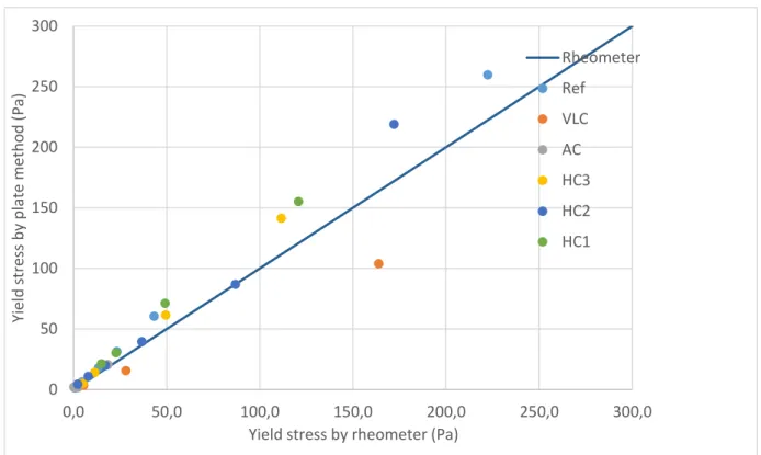
Fig. 8 shows the correlation between plate tests and laboratory rheometer tests.
As seen before, the measured yield stress change according to the position of the cylinder. Here, we choose to use the maximum value of the first phase i.e. the cylinder is totally soaked.
In our results, the factor 0.3 proposed by Maillard et al. (Maillard et al. 2016) in Eq.4 is not usable. According to the earth type, it actually variates from 0.21 to 0.57 and can have a standard variation reaching 0.26.
For every studied earth, the plate test is effective under a 90 Pa yield stress. Then, above 90 Pa, plate test results seem to spread from the reference. As 6 earths are concerned, this should not be influenced by the earth type. This phenomenon can be linked to the used force sensor. As slip yield stress increases, we get too close to the force sensor limit and shows an accuracy decrease. Nevertheless, before 90 Pa, some points indicate a possible 40 % error.
4 CONCLUSIONS
Geotechnical characterizations show that the earths collect campaign allowed to base the study on a representative sample of earth variabilities. In this paper, particle size distribution and CEC are presented, but many other characterization tests have been
performed: Atterberg limits, Methylene Blue Value, pH test, Total Organic Carbon (TOC), specific density, sorption and DRX. Results of these tests will allow a cross analysis between the consistency matrix, geotechnical characterizations, in-situ tests and rheology tests.
Also, only two tests were presented and compared. The complete study will include other tests like slump flow and spreading flow tests and inclined plane test. This paper shows that there is an accurate alternative method for yield stress measurement. The designed plate test is effective and do not seems to be earth-type dependent. With the present design, the only limit of the test is the limit of the force sensor. Other parameters should be tested, like speed of the cylinder movement. Finally, works can be done to transfer this apparatus to an accessible on-site yield-stress measurement.
5 ACKNOWLEDGMENTS
Eco-Terra Project is possible thanks to the financial support of the Normandy Region, the French state, the Fondation de France, the ADEME, the Bretagne Region and the Fondation d’Entreprise Legallais. The authors wish to thank the INRA d’Arras for their rigorous work, and Hervé Bellegou (IRDL – Lorient) for his precious support.
6 REFERENCES
Amziane, S, A Perrot, and T Lecompte. 2008. ‘A Novel Settling and Structural Build-up Measurement Method’. Measurement Science and Technology 19 (10): 105702. https://doi.org/10.1088/0957-0233/19/10/105702.
Aubert, J. E., P. Maillard, J -C Morel, and M Al Rafii. 2015. ‘Towards a Simple Compressive Strength Test for Earth Bricks?’ RILEM, 2015.
Azeredo, Givanildo, Jean-Claude Morel, and Claude-Henri Lamarque. 2008. ‘Applicability of Rheometers to
0
50
100
150
200
250
300
0,0
50,0
100,0
150,0
200,0
250,0
300,0
Yield
s
tr
ess
by
pl
at
e
m
et
ho
d
(P
a)
Yield stress by rheometer (Pa)
Rheometer
Ref
VLC
AC
HC3
HC2
HC1
Characterizing Earth Mortar Behavior. Part I: Experimental Device and Validation’. Materials and
Structures 41 (8): 1465–72.
https://doi.org/10.1617/s11527-007-9343-9.
Bui, Quoc-Bao, Jean-Claude Morel, Stéphane Hans, and Nicolas Meunier. 2009. ‘Compression Behaviour of Non-Industrial Materials in Civil Engineering by Three Scale Experiments: The Case of Rammed Earth’. Materials and Structures 42 (8): 1101–16. https://doi.org/10.1617/s11527-008-9446-y.
Coussot, Philippe, and Stéphane Boyer. 1995. ‘Determination of Yield Stress Fluid Behaviour from Inclined Plane Test’. Rheologica Acta 34 (6): 534–43. https://doi.org/10.1007/BF00712314.
Flatt, Robert J., and Paul Bowen. 2006. ‘Yodel: A Yield Stress Model for Suspensions’. Journal of the American Ceramic Society 89 (4): 1244–56. https://doi.org/10.1111/j.1551-2916.2005.00888.x. ———. 2007. ‘Yield Stress of Multimodal Powder Suspensions: An Extension of the YODEL (Yield Stress MODEL)’. Journal of the American Ceramic Society 90 (4): 1038–44. https://doi.org/10.1111/j.1551-2916.2007.01595.x.
Khayat, K. H., A. F. Omran, S. Naji, P. Billberg, and A. Yahia. 2012. ‘Field-Oriented Test Methods to Evaluate Structural Build-up at Rest of Flowable Mortar and Concrete’. Materials and Structures 45 (10): 1547–64. https://doi.org/10.1617/s11527-012-9856-8.
Lombardi, G. 1985. ‘The Role of Cohesion in Cement Grouting of Rock’. 15ème Congrès Des Grands Barrages, Lausanne, 1985.
‘Lombardi-1985-The Role of Cohesion in Cement Grouting of Rock.Pdf’. n.d.
Mahaut, Fabien, Samir Mokéddem, Xavier Chateau, Nicolas Roussel, and Guillaume Ovarlez. 2008. ‘Effect of Coarse Particle Volume Fraction on the Yield Stress and Thixotropy of Cementitious Materials’. Cement and Concrete Research 38 (11): 1276–85. https://doi.org/10.1016/j.cemconres.2008.06.001. Maillard, M., J. Bleyer, A. L. Andrieux, J. Boujlel, and P. Coussot. 2016. ‘Dip-Coating of Yield Stress Fluids’. Physics of Fluids 28 (5): 053102. https://doi.org/10.1063/1.4947473.
Moevus, Mariette, Yves Jorand, Christian Olagnon, Sandrine Maximilien, Romain Anger, Laetitia Fontaine, and Laurent Arnaud. 2016. ‘Earthen Construction: An Increase of the Mechanical Strength by Optimizing the Dispersion of the Binder Phase’. Materials and
Structures 49 (4): 1555–68.
https://doi.org/10.1617/s11527-015-0595-5.
Perrot, A., T. Lecompte, P. Estellé, and S. Amziane. 2013. ‘Structural Build-up of Rigid Fiber Reinforced Cement-Based Materials’. Materials and Structures 46 (9): 1561–68. https://doi.org/10.1617/s11527-012-9997-9.
Perrot, A., D. Rangeard, and A. Levigneur. 2016. ‘Linking Rheological and Geotechnical Properties of Kaolinite Materials for Earthen Construction’. Materials and Structures 49 (11): 4647–55. https://doi.org/10.1617/s11527-016-0813-9.
Pierre, Alexandre, Christophe Lanos, and Patrice Estellé. 2013. ‘Extension of Spread-Slump Formulae for Yield Stress Evaluation’, 23.
Roussel, N., and P. Coussot. 2005. ‘“Fifty-Cent Rheometer” for Yield Stress Measurements: From
Slump to Spreading Flow’. Journal of Rheology 49 (3): 705–18. https://doi.org/10.1122/1.1879041.
Sleiman, Hassan, Arnaud Perrot, and Sofiane Amziane. 2010. ‘A New Look at the Measurement of Cementitious Paste Setting by Vicat Test’. Cement and Concrete
Research 40 (5): 681–86.
https://doi.org/10.1016/j.cemconres.2009.12.001. Société d’édition du bâtiment et des travaux publics. 2012. Construire en chanvre règles professionnelles d’exécution. Paris: SEBTP.
Sonebi, M, L Svermova, and P.J.M Bartos. 2003. ‘Statistical Modelling of Cement Slurries for Self-Compacting SIFCON Containing Silica Fume’, 2003. Vinceslas, T, T Colinart, E Hamard, A Hellouin de Ménibus, and T Lecompte. 2017. ‘LIGHT EARTH PERFORMANCES FOR THERMAL INSULATION: APPLICATION TO EARTH-HEMP’, 7.