Dynamic Range Implications for the Effectiveness of
Semi-Active Tuned Mass Dampers
by Cory W. Lindh
SUBMITTED TO THE DEPARTMENT OF CIVIL AND ENVIRONMENTAL ENGINEERING IN PARTIAL FULFILLMENT OF THE REQUIREMENTS FOR THE DEGREE OF
MASTER OF SCIENCE IN CIVIL AND ENVIRONMENTAL ENGINEERING AT THE
MASSACHUSETTS INSTITUTE OF TECHNOLOGY MASSACHUSETTS INS E
OF TECHNOLOGY
FEBRUARY 2010 1
MAR 2 3
2010
@
Cory Lindh, MMX. All rights reserved.LIBRARIES
The author hereby grants to MIT permission to reproduce and to distribute publiclypaper and electronic copies of this thesis document in whole or in part in any medium now known or hereafter created.
ARCHvES
Signature of Author:
Department of Civil and Environmental Engineering January 29, 2010
Certified by:
17 Jerome J Connor
Professor of Civil and Environmental Engineering Thesis Supervisor
/
Accepted by:
Daniele Veneziano Chairman, Departmental Committee for Graduate Students
Dynamic Range Implications for the Effectiveness of
Semi-Active Tuned Mass Dampers
by Cory W. Lindh
Submitted to the Department of Civil and Environmental Engineering on January 29, 2010 in partial fulfillment of the requirements for the
degree of Master of Science in Civil and Environmental Engineering at the Massachusetts Institute of Technology.
ABSTRACT
The response of tall buildings subjected to dynamic wind loads has been widely stud-ied. For excitations approaching the resonant frequencies of the structure, ensuring serviceability is a significant concern. One traditional solution is the implementation of a tuned mass damper (TMD), which acts as a passive damping device in the region of the tuned frequency. However, TMDs exhibit a limited bandwidth and often require a significant mass. Active systems, such as the active mass driver, have been utilized to improve the effectiveness of the TMD concept, but these systems require signifi-cant power and bring the inherent risk of instability. Hybrid semi-active schemes with variable damping devices have been proposed. They are stable, require low power, and are controllable, thus providing a broader range of applicability. The concept of a semi-active tuned mass damper (STMD) has been investigated, but the influence of the dynamic range of the semi-active damping device has not been documented. This analysis assesses the effectiveness of STMD systems using a variable-orifice damper and a magnetorheological damper with varying dynamic ranges. Results demonstrate a performance dependence on the dynamic range and also elucidate the superiority of non-linear damping devices. It is shown that the prescribed TMD mass may be reduced by a factor of two when semi-active control is implemented, thereby making the STMD an attractive and feasible option when space and weight concerns govern
design.
Thesis Supervisor: Jerome J. Connor
Contents
1 Mitigating dynamic response of tall buildings under wind excitation 1.1 Motivation ... . . . . . . . . . . . . 1.2 M ethods of control . . . . 1.2.1 Passive control . . . . 1.2.2 A ctive control . . . . 1.2.3 Semi-active control... . . . . 1.3 Selection of a control technique... . . . . 2 Tuned mass dampers for structures
2.1 Development of TMD theory . . . . 2.1.1 Factors influencing TMD 2.1.2 Optimization scheme for 2.2 Application to structures . . . .
2.2.1 Special considerations . 2.2.2 Current examples . . . .
2.2.3 Passive TMD Limitation, 2.3 Active tuned mass dampers . .
2.3.1 Development of concept 2.3.2 Examples . . . .
2.3.3 ATMD limitations . . .
2.4 Semi-active tuned mass damper 2.4.1 Development of concept 2.4.2 Limitations and design is
optimization... . . . . . . . . wind-loaded buildings.. . . . . ..
3 Semi-active damping devices 35
3.1 Variable-orifice damper... . . . . . . . 35
3.2 Friction dam pers . . . . 37
3.3 Rheological dampers... . . . . . . . . 38
3.3.1 Electrorheological fluids.... . . . . . . . . 38
3.3.2 Magnetorheological fluids.... . . . . . . . . 39
3.4 Choosing a damping device . . . . 41
4 Simulation of Controlled System 43 4.1 Equations of motion... . . . . . . .. 43
4.2 Development of model structures... . . . . . . .. 44
4.2.1 Optimized stiffness distribution... . . . . . . . 45
4.2.2 Implementation of Rayleigh damping . . . . 47
4.2.3 Design of tuned mass dampers . . . . 47
4.3 Selection of control algorithm... . . . .. 51
4.3.1 Formulation of state-space equations . . . . 52
4.3.2 Clipped optimal control . . . . 53
4.4 Simulation strategy for frequency-range response.. . . . . .. 54
4.4.1 System input . . . . 55
4.4.2 Time domain numerical integration.. . . . .. 55
4.4.3 Calculation of dynamic amplication factors... . . . . .. 56
4.5 Systems com pared . . . . 57
4.5.1 Free response . . . . 57 4.5.2 Passive TM D . . . . 58 4.5.3 ATMD. . ... . . . . . . . .. 58 4.5.4 Limited ATMD... . . . . . . . 59 4.5.5 Variable-orifice STMD . . . . 59 4.5.6 Magnetorheological STMD... . . . . .. 60
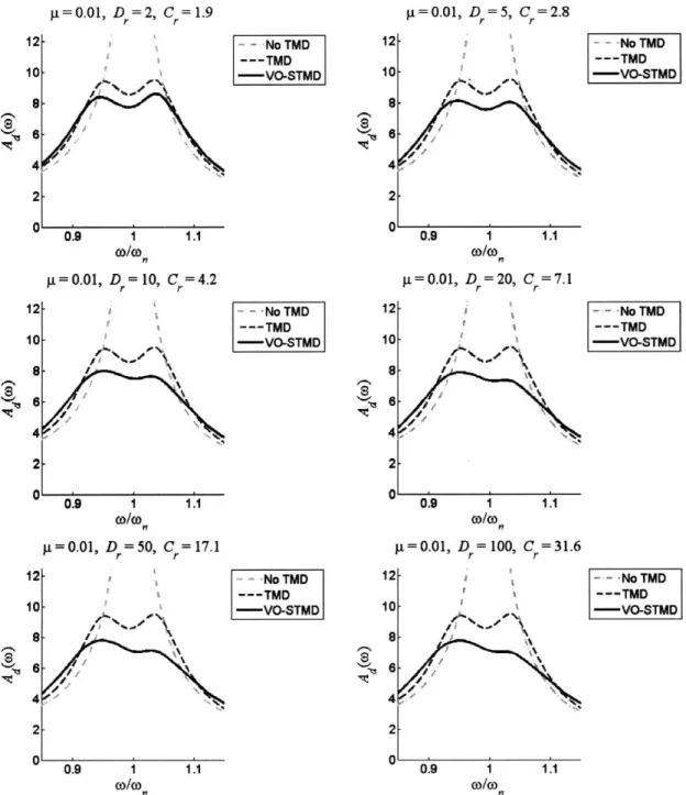
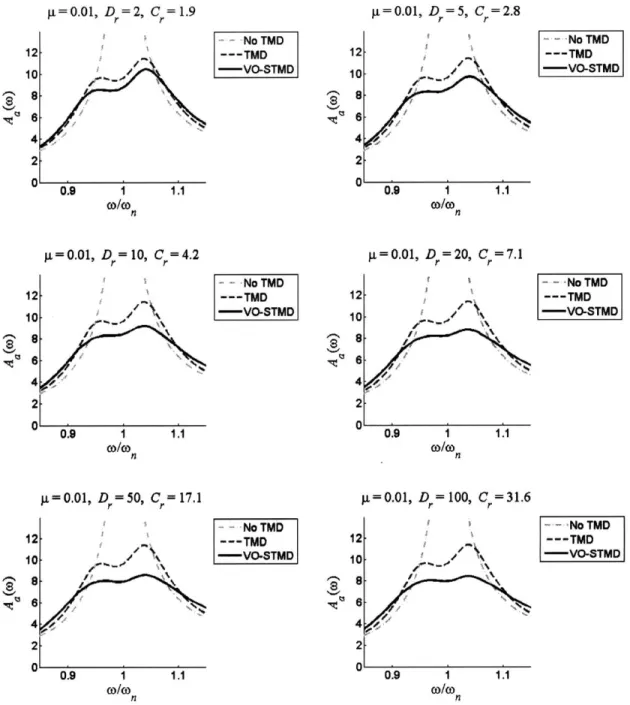
5 Results for Variable-Orifice STMD 63 5.1 Overview of analysis... . . . . . . .. 63
5.1.1 5.1.2
Dynamic range implications . . . . Damping reduction factor implications 5.1.3 Evaluative measures
5.1.4 Broken system considerations
5.2 Results for y- = 0.01 . . . ..
5.2.1 C, optimization . ... 5.2.2 D, variability . . . .. 5.2.3 Other performance measures 5.3 Results for t = 0.03 . . . ..
5.3.1 C, optimization . . . . 5.3.2 D, variability.. . . . . .. 5.3.3 Other performance measures . 5.4 Other mass ratios . . . . 5.5 Summary of results . . . . 6 Results for Magnetorheological STMD
6.1 Overview of analysis . . . . 6.1.1 Dynamic range implications . . . . 6.1.2 Damping reduction factor implications 6.1.3 Evaluative measures.... . . . . .. 6.1.4 Broken system considerations . . . . . 6.2 Results for p = 0.01. . . . . 6.2.1 C, optimization . . . . 6.2.2 D, variability . . . . 6.2.3 Other performance measures . . . . 6.3 Results for y = 0.03 . . . . 6.3.1 C, optimization . . . . 6.3.2 D, variability . . . . 6.3.3 Other performance measures . . . . 6.4 Other mass ratios . . . .
. . . .
. .
.
.
.
. . . .
69 73 76 76 82 87 87 89 93 97 99 104 107 108 109 111 113 113 116 116 122 127 127 127 132 136 1386.5 Summ ary of results . . . . 143
7 Conclusions 147 7.1 Summary of motivation.... . . . . . . . . 147
7.2 Performance of STMD systems... . . . . . . . . .. 148
7.2.1 Reduction in TMD mass... . . . . . . . . . 148
7.2.2 Increase in effective damping . . . . 150
7.2.3 Other performance metrics . . . . 152
7.3 Implications... . . . . . . . . . . . . . 153
7.3.1 Linear vs. non-linear damping devices... . . . . . . . . 153
7.3.2 Impact of dynamic range . . . . 157
7.3.3 Closing rem arks . . . . 158
Chapter 1
Mitigating dynamic response of tall
buildings under wind excitation
Large civil structures are exposed to dynamic loading from a variety of sources, in-cluding earthquakes, high winds, and reciprocating machinery. Satisfactory design must ensure structural integrity and occupant safety under the most adverse condi-tions, the severity of which varies widely based on building location and structural purpose. This study focuses on the specific case of tall, flexible buildings, which are particularly susceptible to wind-induced vibrations and may require more significant control measures to satisfy performance requirements.
1.1
Motivation
Recent decades have marked a trend towards the design and construction of very tall buildings. Advancements in analysis, coupled with an increased use of lighter building materials and a decrease in heavy claddings, have led to structures that are not only taller but also more flexible. Consequently, most modern towers are especially prone to oscillations under persistent winds, which can lead to swaying motions of several
feet on the top floors [12, 39].
In many cases, these large deflections may not threaten the integrity of the struc-ture, but the steady rocking can cause considerable discomfort and even illness to
building occupants. If persistent, the dynamic response under severe winds may render the top floors completely uninhabitable. Studies by Chang and Hansen in-vestigated the effects of this motion on the human body, creating benchmarks for the perception of and physiological response to various increments of lateral accel-eration [12, 17]. Additionally, Ruderman noted that the psychological effects of ob-servable lateral displacements can be a key factor in human comfort, emphasizing the need to limit both quantities - displacements and accelerations - in tall buildings [12].
The maximum amplitudes of these responses are ultimately dictated by the abil-ity of the structure to dissipate energy; the more significant the energy dissipation, the smaller the vibrations. All structures naturally release some energy through mechanisms such as internal stressing, rubbing, and plastic deformations. In large modern structures, however, the total damping may amount to as little as 1% of critical, making them very vulnerable to dynamic effects such as resonance [20]. As a result, additional measures are generally necessary to meet servicability standards. Since eliminating the excitation source is impractical, this necessitates implementing a control scheme to enhance the effective damping of the structure.
1.2
Methods of control
Numerous techniques have been tried to produce better control against wind exci-tation, and these fall into three broad categories: passive control, which provides additional damping with no additional energy; active control, which uses feedback and an external energy source to provide optimized actuator forces in real-time; and semi-active control, which relies on feedback and low-energy devices to provide op-timized reactive forces in real-time. Each of these will be further introduced in this section.
1.2.1
Passive control
The most mechanically simple set of control schemes is encompassed in the passive control categorization, which has thus far been the most accepted for civil engineering
applications.
Definition
Housner et al. [20] and Spencer [55] have both provided comprehensive overviews on structural control, including succinct definitions for the various types of control implemented in structures. They define a passive control system as any that does not require an external power source. All forces imparted by passive control devices develop as direct responses to the motion of the structure. Hence, the energy of both the device and the primary system can never be increased by the control scheme.
The main goal of these systems is to efficiently dissipate vibrational energy, and the various methods of accomplishing this can be categorized in two ways. The first method involves converting kinetic energy directly to heat, such as through the yield-ing of metals, the deformation of viscoelastic solids and fluids, or the implementation of friction sliders. The second method entails transferring energy among two or more of the vibrational modes of the building, generally achieved by installing a supple-mental oscillator that absorbs the vibrations of the primary structure [20].
Implementation for wind-excited structures
Both categories of passive control have been carried out in a variety of ways in the de-sign of tall buildings subjected to dynamic wind loading. The first method, relying on direct conversion of kinetic energy to heat, has been most successfully accomplished through the addition of auxiliary dampers to the primary frame of the structure. These damping devices may be viscous, viscoelastic, or plastic, and are generally dis-tributed throughout the building in a manner that optimizes their energy dissipation. This technique was most notably implemented in the original World Trade Centers in New York City but has also been implemented in several buildings in Seattle and throughout California [20, 37].
The second method of passive control increases effective damping indirectly by modifying the vibrational modes of the structure. In general, the response of struc-tures under wind loading is dominated by the first mode of vibration. Hence, by
adding an oscillatory control device that vibrates out of phase with the structure during resonance conditions, it is possible to use it as a "counterweight" against the fundamental mode, thereby decreasing the overall response of the primary structure. Current passive devices that take advantage of this property include the tuned mass damper (TMD), tuned liquid damper (TLD), and the tuned liquid column damper (TLCD).
Tuned mass dampers, discussed in full in chapter 2, are the most frequently used supplemental oscillators in buildings. Consisting of a mass, spring, and damping element, the TMD is attached to the frame of a structure on one of its uppermost stories. There it is allowed to move out of phase with the rocking building by sliding on low-friction bearings or a thin film of oil, and energy is absorbed through the affixed damper [33, 37]. TMDs have been used throughout the world, but examples in America include the Citicorp Center in New York City and the John Hancock Building in Boston.
Tuned liquid dampers and tuned liquid column dampers utilize oscillations of flu-ids instead of a mobile mass. T LDs are essentially large sloshing tanks, theoretically as simple as a swimming pool, the dimensions of which determine their oscillatory prop-erties. Energy is absorbed through the viscous motion of the fluid and through wave breaking. Notable examples of TLDs in practice include the Shin Yokohama Prince Hotel and a steel-frame tower at the Nagasaki airport, both located in Japan [20]. Tuned liquid column dampers are based on the same concept but rely on the motion of liquid in a U-shaped container with an orifice in the middle. The amount of energy dissipation is contingent upon the inherent heat-loss characteristics and the velocity of the fluid as it passes through this opening. Two 50, 000 gallon TLCDs have been installed in the One Wall Centre in Vancouver [26, 60].
Advantages and limitations
Passive control is the most widely-used method of mitigating structural response under wind loading, but it comes with limitations. While reliable and relatively straightforward to design, passive control systems are generally only good for limited
bandwidths of dynamic input. As a result, they are vulnerable to the effects of off-tuning, de-off-tuning, or resonances of secondary modes. It is primarily due to these limitations that more elaborate active and semi-active control techniques have been coming into practice.
1.2.2
Active control
Active control is a relatively recent subfield of structural engineering; it promises improved response to passive systems at the cost of energy and more complex systems.
Definition
Active control has been described as any control system in which an external power source is required to provide additional forces to the structure in a prescribed manner, generally through the use of actuators. The signals sent to control the actuators are determined based on feedback from sensors placed on or throughout the structure. Due to the presence of an external power source, the forces applied may either add or dissipate energy from the structure [20].
In order to maximize the performance of an active system, the actuator forces must be prescribed in real-time based on the inputs of the sensors. Assigning the direction and magnitude of these forces can be done in a variety of ways, all of which have their roots in the diverse and mathematically rich field of control engineering. Miller provides a useful overview of the breadth of this topic:
Civil engineering researchers have applied both classical and modern control techniques to large civil structures, and have addressed many of the same major issues that have been prominent in the aerospace, electri-cal, and mechanical engineering fields. These issues include such topics as mathematical modeling of structures, identification techniques, reduced-order models, modal truncation and controller interaction with residual modes, placement of control actuators, multivariable controller design techniques, mathematical measures of desired system performance, and
optimal control techniques [39].
In 1972 Yao became the first such researcher to apply control theory to structural problems [20]. Yang followed in 1975 with a study on the application of optimal con-trol strategies for tall buildings subjected to wind loads [68]. Since then, innumerable control algorithms have been developed specifically for civil structures, the basic task of each being to use feedback from sensors to direct the actuator in the best possible way for enhanced serviceability and safety of the structure [33, 55].
Implementation for wind-excited structures
As with passive control systems, there is a significant amount of variety in the de-sign and application of active control systems. More so than with passive systems, however, a majority of active control research has focused on the protection of struc-tures under earthquake loading. Nevertheless, a significant amount of work has also addressed the issues specific to wind-loaded structures, and some control techniques have been adapted for both types of excitation.
Active tendons, also known as active bracing, are an example of an active control technique that has been developed to counteract both earthquake and wind excitation. These devices consist of tendons rigged to the primary structure, the tension of which can be adjusted by actuators. By tightening or slackening these tendons in real-time, it is possible to improve the response of the structure under dynamic loading. Full scale active tendon installation has proven successful for dealing with ground motion and has also been investigated for responding to wind excitation [39, 49].
Other active systems have developed more specifically for counteracting dynamic wind loading, some of which closely resemble successful passive systems. The active mass driver, or AMD, is similar to the passive TMD except that its damper has been replaced by an actuator, allowing for substantially improved control. On the other hand, the active tuned mass damper (ATMD) simply adds an actuator to the original TMD and leaves both the spring and the damper in place. Because the ATMD retains all the components of a passive system, it is sometimes referred to as a "hybrid" control scheme [20].
Both the AMD and ATMD are described more fully in section 2.3, including some successful applications. They have become the most common type of active control implemented in civil structures [10].
Advantages and limitations
The performance benefits of active control are in some cases quite pronounced. Due to its ability to respond in real-time, active control also eliminates most of the tuning limitations inherent in passive devices. However, active control has not been exu-berantly embraced by the civil engineering community as a result of some significant limitations.
Most significantly, the attractiveness of active control schemes is diminished by their heavy reliance on external power supplies. In order to output actuator forces of the magnitude necessary to control large civil structures, the power consumption may become large and costly. Additionally, the times at which the control forces are needed most generally coincides with the time when power failure is the most likely, such as during an earthquake or large wind storm. This raises reliability concerns [39].
Beyond the issue of energy supply, engineers also hesitate to embrace non-traditional technologies for structures. The placement of sensors and the design of feedback schemes are beyond the scope of most practicing engineers, and a poorly designed ac-tive system may lead to deleterious energy inputs and destabilization of the primary system. These legitimate concerns generally sway designers towards more traditional solutions [55].
1.2.3
Semi-active control
Semi-active control seeks to combine the performance benefits of active control and the reliability of passive control, making it a much more appealing alternative to traditional control schemes in civil structures.
Definition
Semi-active control systems are similar to their fully active counterparts in their reliance on real-time feedback to direct a control system, but they differ in that their external energy requirements are orders of magnitude smaller. Generally, semi-active control devices do not add mechanical energy to the primary system and hence have an inherent stability in terms of bounded-input, bounded-output. Consequently, semi-active devices may be viewed as controllable passive devices [20].
Instead of the application of actuator forces, semi-active control relies on the reactive forces that develop due to variable stiffness or damping devices. That is, by altering the properties of these devices, the response of the system may be favorably modified using only nominal power, usually on the energy scale of a battery. As a result, semi-active control strategies appear to combine the best features of fully active and fully passive systems, leaving them with the greatest likelihood of near-term acceptance for structural applications [55, 591.
Implementation for wind-excited structures
Similar to active control techniques, semi-active control schemes may be developed uniquely or may simply modify and improve existing passive control schemes. Aero-dynamic appendages are one example of a novel semi-active technique developed to ameliorate resonance conditions under wind excitation. This concept involves the addition of aerodynamic surfaces to the top of large buildings, the position and ori-entation of which can be modified using only a small amount of energy. A proper control strategy can then derive the requisite control forces directly from the incident winds [2, 39].
More popular semi-active control schemes have been based on adding semi-active damping or stiffness devices to well-tested passive control devices. These include the semi-active tuned liquid column damper (STLCD), in which the orifice in the tube is given a controllable diameter [26], and the semi-active tuned mass damper (STMD), in which the spring or damping element of the passive TMD is replaced with a device
that has controllable properties. The selection of the semi-active device can vary substantially, an elaboration of which is presented in section 2.4.
Advantages and limitations
The most distinct advantage of semi-active systems is their ability to provide improved control forces with an incredibly low demnad for power. Because this power can be supplied by a battery, this ensures continued functionality even in the event of a power failure, adding reliability to any semi-active control method. It is because of these benefits that enthusiasm towards semi-active structural control schemes has increased in recent years, making it a viable alternative to proven passive devices [20].
While these advantages are in some cases truly significant, semi-active control still has its detractors. Most relevant is the need for sensor technology and computer-controlled feedback, which is as central to semi-active control as to active control. The risk of destabilization has now been removed, but the design engineer must be convinced of the performance benefits of adding semi-active devices before he is willing to embrace a more intricate, less proven technology.
1.3
Selection of a control technique
As has been seen, there are numerous methods for addressing even the specific control problem of wind-excited tall buildings. While several of the control methods have received a great amount of attention in the literature, the greatest precedent lies with mass-based oscillators, whether passive (TMDs) or fully active (AMDs and ATMDs). With the more recent rise of semi-active control strategies, STMDs have also received quite a bit of attention, but none have yet been installed in a full-scale civil structure. This thesis purposes to expand knowledge of STMD systems, specifically by an-alyzing their effectiveness as a function of the properties of the variable damping device selected to provide the semi-active control. To do so, the use of tuned mass dampers will be overviewed (chapter 2), various semi-active damping devices will be compared (chapter 3), and performance simulations will be generated (chapter 4).
Comprehensive results for two specific STMD systems will be presented in chapters 5 and 6, both of which will evidence the benefits of adding semi-active control to a traditional tuned mass damper (chapter 7).
Chapter 2
Tuned mass dampers for structures
As mentioned in chapter 1, the most widely accepted control measure for mitigating the response of tall structures under wind loads is the implementation of a tuned mass damper, or TMD. The concept has been well-established and at its base level is relatively uncomplicated. Consisting of a mass, a spring, and a damper, the natural frequency of the TMD is tuned to have a resonance very close to the fundamental mode of the primary structure, which allows a large amount of the structure's vibrational energy to be transferred to the TMD and then dissipated by its damper. This system has been adapted in numerous tall structures, and it has proven to be an effective method for mitigating structural vibration under high wind loads.
This chapter summarizes the vast amount of work done on TMD systems, explains appropriate measures for the optimization of its parameters, and describes the more recent work done in implementing active and semi-active control to enhance and extend the performance of tuned mass dampers.
2.1
Development of TMD theory
Although the basic TMD framework is quite simple, the specific parameters for its mass, stiffness, and damping must be found by using optimal design procedures to maximize its control effectiveness. These expressions are generally developed using a linear single degree of freedom (SDOF) model to represent the vibration of the
'I
Figure 2-1: Basic TMD model
fundamental mode. The literature on this topic is both extensive and varied, as design equations depend not only on the parameters of the primary structure, but also on system inputs and optimization goals. In all cases closed-form solutions exist for these parameters when the sub-structure has no inherent damping (c = 0 in figure 2-1), with numerical and series solutions available for the more complicated case where c -/ 0 [5].
2.1.1
Factors influencing TMD optimization
Certainly, not all TMD design procedures are equally beneficial for their placement in structures subjected to wind loading. Before any methods are excluded, however, all TMD design factors will be summarized, with references provided for further information.
Type of excitation input
Except for the special case where c = 0, optimal TMD parameters vary based on the type of excitation. The types of loading most commonly considered are
* An excitation force applied directly to the main mass, which for structural applications would include wind loading [5, 18, 44].
p
p pe1i
ug = ue p = atpoe!"
@
Q
Figure 2-2: Types of excitations
e An acceleration of the structure's base, which is used to model the effects of earthquakes on structures [57, 58].
9 An inertial force applied to the main mass, which would describe the effects of an eccentric mass vibrator [52].
Examples of these loadings can be seen in figure 2-2, where
@
represents wind excitation,@
represents ground excitation, and @ represents inertial excitation.Output to be minimized
Selection of optimal TMD parameters further depends on which system output is to be minimized. In general TMD applications these may include the displacement, velocity, or acceleration of the primary mass, as well as the force transmitted to the mass or the relative motion of the mass with respect to the base. Summaries of the results for each of these design goals can be found in [61].
Optimization goal
Even when the excitation input is known and the output to optimize has been selected, there are still three possibilities for optimization criterion from which to choose [5].
" H, optimization minimizes the maximum amplitude response of the system. Expressions are developed by applying minimization techniques to harmonic force inputs [5, 44, 47].
" H2 optimization minimizes the total vibration energy of the system over all
frequencies. In this case, derivations come from minimization of the ensemble mean of the response under random white noise excitation [5, 14, 61].
" Stability maximization attenuates the transient vibration of the system in the shortest amount of time possible. Mathematically, this is accomplished by mov-ing all poles of the transfer function of the system as far to the left of the imaginary axis as possible in the s-plane [41, 64].
Both the H, and H2 optimization criteria seek improvement for the steady-state
response of the structure, while the stability maximization objective aims to improve transient behavior. Figure 2-3 demonstrates how the transfer function of the TMD system varies based on the goal of the optimization.
2.1.2
Optimization scheme for wind-loaded buildings
As can be seen, the procedures for optimizing a TMD are numerous. This necessitates using engineering judgment to select the best expression for the TMD parameters. In the case of tall buildings, both wind and earthquake loading have been considered, but the mitigation of vibrations due to winds is generally the design goal of any TMD system; hence, the model for an excitation force applied to the primary mass will be chosen. As discussed in section 1.1, both displacements and accelerations are dominating design concerns. Tthe selection between these two does not affect the result significantly, so following convention the displacement will be the selected
H.optimization H12 optimization 5-4 5 -~ 25- 1 -024
I0
1 5ii -5 ie3peak value Mimze
0 5 -Figureimizatiomp
li
--- Uncontrolle it-- With TMD Deel n of Vf 0 2i 2 1. 1.inmie 00 000.5 1 1.5 2E ft s Fiubet2-3:Co of i optimization eae
cant amount of progression. Indeed, minimization of maximum displacements under harmonic loads was the original objective of early TMD research.
Using a secondary mass to limit displacements at resonance was first proposed by Frahm in 1909 [16]. The benefits of a TMD with a damper was first shown by Ormondroyd and Hartog in 1928, who demonstrated its success experimentally [44]. For a given TMD mass, it was later shown that optimizing the response consisted of two distinct steps: tuning the frequency of the damper and selecting the ideal level of damping. The frequency tuning parameter, fot is based on the fact that the TMD introduces a second frequency to the system, which if carefully selected will produce equal responses at the two resonances of the combined system. An expression for fopt 'Indeed, as shall be shown in the results sections, the addition of a semi-active device to a TMD has the greatest overall effect when TMD parameters are optimized for displacement rather than acceleration. This is due to the semi-active TMD being more effective for higher frequencies, which is where the dynamic response of the acceleration deviates from optimum for a system optimized for displacement.
was first developed by Hahnkamm in 1932 [5]. The second step involves selection of the optimum damping ratio, (opt, the theory for which was first developed by Brock in 1946 [8]. His approach is now known as the "fixed points" theory, since it is based on the recognition that there are two points in the system response (one near each resonance) through which all curves pass regardless of TMD damping; hence, (opt is selected such that these points become local maxima.
These parameters were also developed independently by Den Hartog, who put them into wider use with release of his textbook in 1956 [18], but they lacked com-pleteness in that they were only valid for an undamped primary system. In 1981 Randall expanded this theory by producing numerical curve-fitting results for find-ing
fopt
and (opt when c / 0 [47]. A variety of other curve-fit solution have also been produced, and recently Asami presented a series solution to this problem [5]. It is believed that an exact analytical solution for damped systems will never be at-tained, but the numerical and series solutions are certainly sufficient for engineering applications.Optimization equations
For a give mass ratio, yt, defined as the mass of the TMD divided by the mass of the
primary structure, the H, optimized parameters for tuned mass dampers limiting displacements are as follows. In the case of no damping2
fopt
1 (2.1) 1+p 3p &opt = (2.2) 8 (1 + p) 2When c - 0, the closed-form analytic solution for Ho, optimization is identical for all types of excitation inputs described previously.
and in the case of a primary structure with ( as its damping ratio3 1 1 '1 (4 AB
fort
=
-
1
(3+ 4p,-
)B
(2.3)
1+ y
1 + p- 2 (1 + p)
2 + p
3p 60 + 63p + 16p 2 - 2(3 + 2,)ABopt =+
(2.4)
""8(
+ p)
8(1 + p-) (2 + p-) (9 + 4p)
where A = "3(2+ p) - p(2+ p)B = )3(2 + p) + 1/p(2+ p)
2.2
Application to structures
Though most TMD theory developed for use in mechanical engineering applications, it has proven to be an effective means of addressing the resonance issues in tall buildings described in section 1.1. In many instances, they have been shown to reduce response amplitudes by as much as 40%. The basic concept remains unchanged, with the TMD acting as an energy-absorbing system with parameters optimized to the structure's fundamental mode of vibration. There are, of course, special design considerations due to the much larger scale, but the TMD has been successfully employed in several tall buildings. Current applications include translational tuned mass dampers, in which a large mass is placed on bearings or a near-frictionless oil film and fastened into a structural frame, as well as pendulum tuned mass dampers, in which a large mass is allowed to rock back while hanging from a large rod, the length of which determines its tuning.
3The full series, developed by [5], also includes (2 terms, which are excluded here due to their minimal contribution to lightly damped systems. For full expressions, see section 4.2.3
2.2.1
Special considerations
The first and most significant design consideration unique to tall civil structures is the amount of mass that can be placed on the top of the tower. p, the mass ratio, is the most influential parameter in terms of TMD effectiveness; once the mass ratio is specified, it only remains to size optimal spring and damper elements. However, due the large mass of structures, practical design considerations limit P to a range of
0.005 - 0.02 [37].
A second consideration that must be taken into account during the design process is the relative movement of the TMD with respect to the building4. In addition to space constraints, stroke limits must be met. For example, in translational tuned mass dampers, pneumatic springs may be used for the stiffness and hydraulic shock absorbers for the dampers, which in both cases have inherit extension limitations [37]. Relative displacements may be decreased by increasing either P or cd. Consequently,
since the mass ratio is generally fixed, it may become necessary to overdamp the TMD, which has the deleterious effect of increasing the response of the primary structure [50]. This trade-off becomes a matter of engineering judgment.
Thirdly, there is the practical difficulty of creating a low-friction surface for the damper mass. Friction forces must be small enough to enable the damper mass to respond freely even for low levels of building excitation. In translational tuned mass dampers, this may entail using a thin oil film [37].
2.2.2
Current examples
Both translational tuned mass dampers and pendulum tuned mass dampers have been used in significant and progressive structures. This section highlights some examples.
Citicorp Center
The Citicorp Center in New York City was the first to complete installation of a full-scale structural tuned mass damper. When finished in 1977, its 400-ton control 4For reference, full-scale lab tests produced relative displacements of around 3.5 feet under the wind loading of a 10-year storm [37].
mass was 250 times larger than any existing TMD. With a mass ratio of 2% of the first modal mass, the damper increased overall structural damping from 1% to 4% of critical, which reduced sway amplitude by a factor of 2. The TMD system consists of a large block of concrete bearing on a thin film of oil, with structural stiffness provided by pneumatic springs [13, 37].
CN Tower, Toronto
The Canadian National Tower in Toronto is unique from a design perspective in that tuned mass dampers had to be added to suppress the motion of the second and fourth modes of vibration. It was not the 553-meter tall tower in its entirety, but rather the
102-meter steel antenna at the top that required suppression of dynamic wind loading effects. Because the first and third modes of the antenna had the same vibrational characteristics as the more heavily damped concrete structure, they did not require
any additional damping.
To dampen the vibrations, two doughnut-shaped steel rings with 9 tons of dead-weight were added at elevations corresponding to the peak vibrations of the prob-lematic modes. Each ring was mounted on a universal joint that could rotate in all directions, thereby allowing it to act as a tuned mass regardless of the direction of wind excitation. Energy dissipation is provided by four hydraulically activated dampers per ring [13, 53].
Taipei 101
Taipei 101, the tallest building in the world at the time of its completion in 2004, exemplifies how a tuned mass damper can double as a significant architectural and visual element. Rather than sliding on bearings in an enclosed room, the Taipei 101 TMD rocks like a pendulum in a fully open viewing area at the top of the building. The mass is provided by an impressive 6-meter-diameter steel ball weighing 726 tons. Suspension of this enormous sphere is made possible by four sets of cables, and dynamic energy is dissipated by eight hydraulic pistons each measuring two meters in length. When in full motion, this system is capable of maintaining acceptable levels
of lateral acceleration under wind gusts of up to 150 mph [48].
2.2.3
Passive TMD Limitations
While tuned mass dampers have proven to be effective at mitigating structural vi-brations caused by high winds, they also possess some pointed limitations.
The first and most obvious limitation is that, as its named suggests, a TMD is "tuned" to a very narrow band of suppression frequencies. Hence, if other modes of resonance are also significant concerns, the specificity of its tuning renders the TMD ineffective to suppress them [46].
A corollary of this limited tuning range is the risk of a mistuned system. In practical applications, this may occur for two reasons. First, structural properties are only known with a degree of uncertainty, meaning that even a carefully-optimized TMD system is liable to be sub-optimally calibrated to the resonance of the structure's fundamental mode. Second, even if the structural properties are accurately assessed initially, they are prone to vary with time; for example, both variation in mass and deterioration of the structure could negatively affect its tuning [27, 50].
Finally, it is noted that wind excitation is generally neither harmonic nor white noise, both of which have been used as assumptions in TMD optimization. Addition-ally, even with detailed wind-tunnel models, it is difficult to predict the impact of wind loads due to changes in topography, neighboring buildings, and the results of vortex shedding [50].
These disadvantages do not negate the overall feasibility of TMD systems, but they do threaten to limit their effectiveness. Consequently, methods for improving the passive TMD system with active or semi-active control have been explored.
2.3
Active tuned mass dampers
In an effort to overcome these limitations and to improve performance, measures have been taken to incorporate active control techniques with passive TMD systems,
as mentioned in chapter 1. The basic concept involves adding an external energy source to generate an additional force that complements the force generated by the TMD, usually through the use of an actuator. With the inclusion of sensors and a feedback loop, the actuator force can be adjusted nearly real-time to produce opti-mized results.
There are many motivations for using an active TMD system, but there are a few particularly significant benefits. First, adding an external force can greatly increase the control system's effectiveness while also mitigating the limitations posed in sec-tion 2.2.3. Second, it can allow the size of the mass to be reduced, alleviating potential space and weight constraints. Third, an active system can be used to reduce the rel-ative TMD displacement, thereby addressing limitations on stroke length [53]. As a result of these distinct advantages, the active TMD has become a widely accepted application of active control in civil structures [4].
2.3.1
Development of concept
There are a number of variations to the active TMD concept, ranging from the place-ment of the actuator to the control scheme used to direct it. This section describes the more common design possibilities and highlights advancements in the theory.
Variations of design
The most basic design is known as an active mass driver (AMD) and consists of a force actuator driving a mass connected to the building by a stiffness element. In this set-up there is no passive energy dissipation; the desired control forces are obtained directly through the reaction of the AMD system acting on the building.
Another scheme is the active tuned mass damper (ATMD), which includes the passive damper of traditional tuned mass dampers. Hence, the actuator is placed in parallel with the stiffness and damping elements and is programmed to enhance the behavior of the passive TMD.
Actuator
(v)
'''d
Actuator Actuator Md(
)
(
Figure 2-4: Types of active mass drivers
TMD. This design involves attaching an auxiliary mass and an actuator to the tuned mass damper. The purpose of this smaller-scale AMD is to drive itself out of phase with the passive mass damper, producing an additional force that complements the natural motion of the TMD [13, 33].
Basic schematics of each of these devices can be seen in figure 2-4, which portrays the AMD, @, the ATMD, @, and the DUOX, @.
Advancements in theory
A significant amount of literature has been produced on the benefits of actively-controlled tuned mass dampers. This work has included analyses of ATMD effec-tiveness under both earthquake and wind loading. To date, a majority of published results has concentrated on earthquake-loaded buildings, as this is a frontier that passive TMD systems have proven relatively ineffective at targeting. Nevertheless, since tall structures are more prone to wind-loading issues at their resonant frequen-cies, work on both issues has been on-going. Because this thesis addresses large
wind-loaded structures, the literature on this topic will be summarized.
The concept of using active control elements to enhance TMD performance was first proposed by Lund in 1979 [32]. In 1980, Soong applied optimal control the-ory to an ATMD to demonstrate its superiority over passive systems at mitigating wind-induced vibrations [53]. Abdel-Rohman advanced the theory in 1984 by de-scribing how the optimization of the passive TMD parameters must be modified if minimization of energy consumption is to be taken into account [1]. In following years, various attempts were made to produce closed-form optimized solutions of both the passive parameters and the gain coefficients of the closed-loop full-state feedback system [4, 11, 65]. Mackriell further demonstrated ATMD feasibility by using pure acceleration feedback to control simulated high-rise structures subjected to digital time histories of wind-tunnel results [33].
In addition to assessing the overall effectiveness of ATMD systems, work has also been done to specifically address concerns of the actuator stroke. As in the passive TMD case, the relative displacement of the damper mass with respect to the floor can be a significant design issue. Soong demonstrated that this relative displacement can be significantly decreased through use of the ATMD [53]. Ideka was the first to develop guidelines for using LQR control theory to weight the stroke of the actuator [22]. Sakamoto undertook both experimental and theoretical measures to develop an AMD with a limited stroke [51].
2.3.2
Examples
Advances in ATMD theory has been complimented by its success in several structural applications, though predominantly in Japan.
Kyobashi Seiwa Buidling
The first practical application of an AMD was in the Kyobashi Seiwa Building, a slender 11-story building located in Tokyo, Japan. In 1989 two AMDs were installed on the top floor to control both lateral and torsional vibrational modes under ground
or wind excitation. The fully-active system consists of sensors on several locations, a control computer for signal analysis, actuators with 0.01 second response times, and the two large masses. Lateral response of the building was successfully decreased by a factor of three as compared to the uncontrolled structure [10, 13].
Ando Nishikicho building
The Ando Nishikicho building in Japan exemplifies the use of a DUOX active-passive hybrid TMD system. This 14-story building in crowded downtown Tokyo is sus-ceptible to strong wind gusts due to the contours of surrounding buildings. The DUOX control system designed to solve this problem consists of two active mass drivers mounted in orthogonal directions to control vibrations along either primary axis. Sensors were placed on both the AMD and TMD, as well as throughout the building to monitor ground excitation and building response. The computer directs the actuators to both optimize the response of the structure and to limit the stroke of the AMDs [13].
2.3.3
ATMD limitations
The performance benefits of an ATMD are now obvious, but these are not made available without some significant drawbacks.
Perhaps the most serious disadvantage of an active system is the steep increase in cost. Installation of the device itself becomes more complex, as now sensors, feedback connections, and actuator devices must be taken into account. Furthermore, these systems may require both large amounts of power and tedious regular maintenance, both of which add to the long-term operational costs.
Active systems also pose instability risks that need not be considered with passive devices. For example, a malfunction of the system control could cause the actuator to erroneously add energy to the primary structure, thereby having an adverse effect on vibration mitigation. Additionally, any large scale power outage could render the benefits of active control completely useless.
Due to both cost and instability considerations, many have explored alternatives to fully active TMD systems.
2.4
Semi-active tuned mass dampers
As described in section 1.2.3, recent work has championed the promise of semi-active design strategies to blend the performance benefits of semi-active systems with the stability and energy advantages of passive systems. This concept of hybrid design has also been applied to TMD systems. In a semi-active tuned mass damper (STMD),
additional forces are developed through variable stiffness or damping devices rather than through the direct application of an active control force.
Utilizing semi-active control with TMD systems is attractive for several reasons. First, it allows for variations in the control force to optimize system performance without the addition of a significant energy source, since devices that vary the stiffness or damping forces require only nominal power. Second, because these control forces dissipate energy rather than add it, they are inherently stable. Consequently, even in the event of a control system malfunction or a system power loss, an STMD may still behave as an effective passive system.
2.4.1
Development of concept
Similar to ATMD design, there are several basic variations of STMD systems that have been considered.
Variations in design
By far the majority of work on STMD systems has focused on improving transla-tional passive TMDs5, with the reactive control forces coming from installing variable stiffness or damping elements. Semi-active variable stiffness (SAIVS) devices involve replacing the pneumatic springs of the traditional TMD with a mechanical device
JOINT2
El
Linear Electronechanical Actuator/ ContralterFigure 2-5: Semi-active variable stiffness device [40]
capable of adjusting its stiffness as necessary for optimized performance. This af-fords the distinct advantage of allowing a continuous retuning of the TMD frequency, thereby improving control and providing robustness against all off-tuning effects. An example of a SAIVS device developed by Nagarajaiah [40] is shown in figure 2-5.
On the other hand, damper-based STMD design involves replacing the passive dissipative element with a variable damping device. Many such devices, including variable-orifice dampers, rheological dampers, and variable friction dampers have al-ready proven successful, with details in the following chapter. These variable dampers are used to adjust the level of energy dissipation in real-time to optimize the perfor-mance of the TMD. Due to their documented feasibility in large-scale civil structures, variable damping devices have generally been preferred to the more mechanically in-tricate SAIVS devices for implementation in STMD systems.
Advancements in theory
As with ATMD studies, the literature on STMDs has focused both on loaded and wind-loaded structures, with a noticeable preponderance towards earthquake-excited structures. Because work on both cases is more limited for STMD systems, the significant results for all excitation types will be summarized.
The concept of a semi-active tuned mass damper was first proposed by Hrovat in 1983, who in essence simulated results for a force-clipped ATMD that was prohibited from adding energy to the system [21]. The first practical applications investigated used electrorheological (ER) dampers to supply the semi-active forces; in 1995 Abe developed ER-STMD theory for controlling transient responses under impulse load-ing [3], and in 1999 Hidaka conducted experimental studies that coupled an ER-STMD with a three-story model building under ground excitation [19]. Both demonstrated improved performance.
With the emergence of magnetorheological (MR) dampers as preferable to ER devices for structural applications (see chapter 3), more recent work has focused on MR-based STMD systems. Koo assessed various groundhook-based control al-gorithms and demonstrated their effectiveness through an experimental study of a base-excited SDOF model structure coupled with an MR-STMD [27, 28]. Ji further evaluated semi-active control algorithms for controlling an MDOF structure subjected to earthquake loading when there are uncertainties about structural properties [24]. Performance benefits of an MR-STMD under earthquake loading were further doc-umented by Loh through numerical simulations of the response of a 12-story build-ing [30].
Other significant work has focused specifically on wind-loaded structures. Pinkaew was the first to demonstrate the steady-state efficacy of a damper-based STMD by simulating frequency-domain results due to harmonic excitation [46]. Varadarajan proposed a novel device for a stiffness-based STMD capable of retuning to meet the demands of realistic wind excitations and changes in the stiffness properties of the primary structure [59].
At this point, no semi-active TMD devices have been installed in an actual civil structure, but theoretical work remains on-going due to the great potential of semi-active devices.
2.4.2
Limitations and design issues
There are evident advantages in equipping tuned mass dampers with semi-active control, but these, too, come with their own design challenges.
First, while STMD costs may be significantly reduced compared to ATMD costs -particularly with regards to power consumption and maintenance - installation costs still include sensors, control software, and the necessary wiring. Hence, it must be shown that the use of feedback control is still a worthwhile investment.
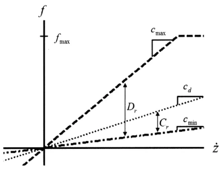
Second, and more importantly, the effectiveness of any STMD is ultimately limited by the control flexibility afforded by the semi-active device, whether it be through variable stiffness or variable damping. As mentioned previously, the mechanical dif-ficulties associated with variable stiffness devices generally make them a less attrac-tive option, which leaves the designer with the task of choosing the best variable damping device for the STMD system being considered. Realistic damping devices, such as variable-orifice, magnetorheological, or friction-based dampers, have inher-ent limitations in their maximum force, accessible range of forces, and stroke length. Consequently, it is critical to understand these limitations in order to produce an optimally-designed semi-active tuned mass damper.
Chapter 3
Semi-active damping devices
Selecting an optimal damping device for a given control application involves assess-ing a host of design considerations, includassess-ing not only maximum force output, but also reaction time, power requirements, reliability, size, and stroke limitations. This chapter summarizes the capabilities of the three classes of semi-active devices that have been considered for structural applications: hydraulic dampers with a variable orifice, friction dampers, and controllable fluid dampers.
3.1
Variable-orifice damper
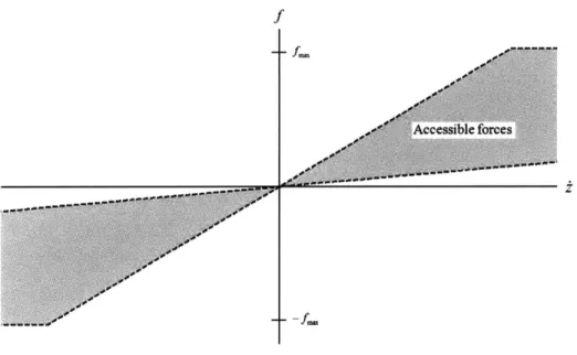
The variable-orifice (VO) damper was the first semi-active damping device imple-mented in structural applications. It consists of a cylinder-piston system with a by-pass valve connected at both ends and behaves essentially like a conventional hy-draulic fluid damper with adjustable resistance to fluid flow. By electromechanically controlling an orifice in this valve, it is possible to greatly vary the damping force in real-time. Consequently, VO dampers may be modeled mathematically as linear viscous dampers in which the damping coefficient, c, now becomes a manipulable variable, c(t). A basic schematic of the VO damper can be seen in figure 3-1.
Controllable Valve
Load
Figure 3-1: Variable-orifice damper schematic [55] Industrial-sized devices
Kurata [29], Matsunaga [35], and Niwa [42] have each contributed to the development and classification of VO dampers capable of performing on a structural scale. These devices can produce maximum force outputs of 1-2 MN and require a power supply of only 70 W. The dynamic range of the dampers, which is determined by the minimum and maximum values for the damping coefficient, c(t), is in excess of 200. These devices are relatively space efficient, with dimensions of 1.5 x 0.5 x 0.5, in meters, and a mass of around 1, 300 kg.
Structural applications
VO dampers have proven successful in several applications in civil structures. In 1994 Patten led installation of VO dampers on an 1-35 bridge in Oklahoma to dissipate energy induced by vehicle traffic, marking the first full-scale implementation of struc-tural control in the United States [45]. Kobori implemented VO dampers to control stiffness elements in a semi-actively controlled building at the Kobori research com-plex [20]. Kurata was the first to make VO dampers the primary control system of a full-scale building, using several of the 1 MN models. Each of these advancements, among others, has led to acceptance of VO dampers as a viable means of improving control performance on a large scale.
+
N(t(t)
+
Figure 3-2: Variable-friction damper schematic [69]
3.2
Friction dampers
A second class of semi-active damping devices is based on variable friction elements. These dampers consist of a frictional sliding surface and a clamping device that pro-duces a normal force at the interface. Controllability comes from varying the magni-tude of the clamping force in real time. Various techniques have been employed to generate the normal force, including electrically-controlled piezoelectric material [63] and magnetic attractive forces produced by solenoids [69]. A schematic of the latter device is shown in figure 3-2; in this configuration the normal force, N(t) is directly proportional to the square of the current, I, in the solenoids, which are placed on either side of the interface.
Industrial-sized devices and structural applications
Although friction dampers have been lauded due to their insensitivity to tempera-ture, their minimal degradation due to aging, and their complete absence of leakage problems, they have been the least utilized semi-active damper in structural engineer-ing applications [31]. Most of their applications have been in conjunction with other
semi-active devices or in specialized situations. For example, Feng and Yang used friction-controllable fluid bearings in parallel with seismic isolation systems to im-prove performance under earthquake loading [20]. Xu demonstrated friction damper effectiveness for the control of large truss structures under wind loads [63], but few other systems use friction dampers as the primary control mechanism.
3.3
Rheological dampers
The final class of semi-active damping devices utilizes the controllability of rheo-logical fluids. The essential characteristic of these fluids is their ability to reversibly change from free-flowing linear viscous fluids into semi-solids with a controllable yield strength. This change in material property can be imparted in milliseconds through the application of either an electric field or a magnetic field, depending on if an electrorheological (ER) or magnetorheological (MR) fluid has been chosen [20].
Rheological fluids have garnered a significant amount of attention in the engi-neering community due to their mechanical reliability. Unlike the other choices for semi-active dampers, rheological dampers have no moving parts except for a pis-ton. Without any electrically controlled valves or additional mechanical components, rheological fluids can provide simple, quick, and quiet interfaces between control elec-tronics and the mechanical system [20].
3.3.1
Electrorheological fluids
ER materials were the first rheological fluids to undergo extensive study. These fluids consist of micron-sized particles suspended in high dielectric strength oils. Upon the application of an electric field, the suspended particles become polarized and fibrate into inter-electrode bridges, producing a solidified material mixture. Once in a solid state, ER fluids experience yield stresses in shear on the order of 10 kPa for static loading and 5 kPa for dynamic loading. Response times vary from 1 to 10 ms, and dynamic ranges exceeding 1, 000 have been obtained [34, 36].
Wires to Electromagnet
MR Fluid Ma eic Accumulator
Rod Piston
Figure 3-3: Magnetorheological damper schematic [55] Structural applications
Application of ER technology has been extensive, but it has not been developed on the structural scale. ER fluids have been successfully used in clutches, breaks, tunable engine mounts, shock absorbers, robotics, and aerospace structures [34]. However, ER fluid use diminished by the time structural control gained traction at the end of the twentieth century, primarily because further advancements in MR fluids demonstrated its superiority for control purposes.
3.3.2
Magnetorheological fluids
MR fluids are the magnetic analog to ER fluids. They are comprised of micron-sized magnetically polarizable particles dispersed in a carrier medium such as silicon oil, meaning they take on semi-solid, viscoplastic tendencies when exposed to a magnetic field instead of an electric field. Only recently have they been considered for ap-plications in place of ER fluids [20]. See figure 3-3 for the design of a typical MR damper.
Preferability of MR fluids
With the recent increase in knowledge of MR fluids, several distinctive advantages have surfaced over ER fluids. Perhaps most significantly, MR fluids are capable of

![Figure 2-5: Semi-active variable stiffness device [40]](https://thumb-eu.123doks.com/thumbv2/123doknet/14754464.581825/32.918.294.653.129.491/figure-semi-active-variable-stiffness-device.webp)
![Figure 3-2: Variable-friction damper schematic [69]](https://thumb-eu.123doks.com/thumbv2/123doknet/14754464.581825/37.918.313.590.127.469/figure-variable-friction-damper-schematic.webp)