EDDY CURRENT LOSSES IN A CONDUCTING SHAFT
ROTATING IN A MAGNETIC FIELD
N. H. FRANK
TECHNICAL
REPORT
NO. 23
NOVEMBER 20, 1946
RESEARCH LABORATORY OF ELECTRONICS
MASSACHUSETTS INSTITUTE OF TECHNOLOGYThe research reported in this document was made possible
through support extended the Massachusetts Institute of
Tech-nology, Research Laboratory of Electronics, jointly by the Army
Signal Corps, the Navy Department (Office of Naval Research),
and the Army Air Forces (Air Materiel Command), under the
Signal Corps Contract No. W-36-039 sc-32037.
MASSACHUSETTS INSTITUTE OF TECHNOLOGY Research Laboratory of Electronics
Technical Report No. 23 November 20, 1946
EDDY CURPENT LOSSES IN A COiNDUCTING SHAFT ROTATING IN A MiGEZTIO FIELD
by N. H. Frank
Ab stract
The eddy curent losses in a shaft rotatirng in a uniform magnetic field perpendiclar to the shaft axis are calculated, when the shielding effect of the induced currrent is included. Plots are given to show the increasing distortion of the magnetic field in and around the shaft with increasing ratio of radius to
skir depth for the rotation freuency, for non-magnetic shaft material. Formulas
EDDY CURRENT LOSSES IN A CONDUCTING SHAFT ROTATING IN A 4AGNETIC FIELD
1. In recent design considerations of large synchro-cyclotrons, the problem of computing the eddy current losses in a metal shaft rotating in a uniform magnetic field perpendicular to the shaft axis has arisen. This shaft is used to drive the rotating plates of a variable condenser used to produce the requisite frequency modula-tion for the dee voltages. Although the solumodula-tion of this classical problem may exist in the literature of many years ago, it seems worthwhile to make the solution readily available.
Let the metal shaft of radius A be driven with a constant angular velocity
S
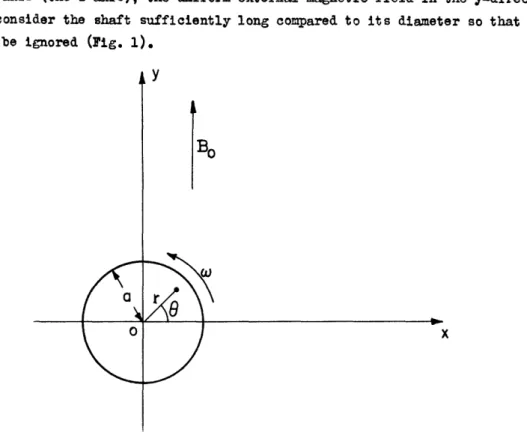
about its axis (the z-axis), the uniform external magnetic field in the y-direction be Bo, and consider the shaft sufficiently long compared to its diameter so that end effects may be ignored (Fig. 1).a
0
, Y
BO
S
~~~~~~~x
Figure 1. Shaft of radius a rotating in uniform mag-netic field Bo perpendicular to shaft axis.
There will be induced in the shaft a steady space distribution of currents parallel to the axis, and since it is metallic one may neglect the contribution of the displacement current to the total current. Furthermore, the velocity of any point of the shaft is so small compared to the velocity of light that one may use the classical form of
Maxwell's equations for moving media. For the problem at hand, since all partial deriv-atives with respect to time vanish, these take the form
url[E - ( x B)] =
(1)
curl H = r
where c- is the conductivity of the metal. These equations are valid inside the shaft. For all exterior points we have the same equations with v = r = 0.
-1-At the surface of the rotating shaft, the boundary conditions require the continuity of the tangential and normal components of H and B, respectively. The tangential component of E is, however, discontinuous at this boundary. From the first
of Eqs. (1), one has
E = (v x B) - grad f
(2)
and since (v x B) is everywhere parallel to the shaft axis and end effects are being neglected, we may set the scalar potential yp equal to zero. By inserting Eq. (2) in
the second of Eqs. (1), there follows
cur H =
a-(v
x B); (3)(v x B) has a z-component equal to (-mnBr), the remaining components being zero. We set
B = curl A, Az = A(r,Q); Ar = A =- 0 and obtain from Eq. (3)
so that div A = 0
curl curl A = - A =
_
msince B =1 A r r 0 '
In polar coordinates Eq. (4) becomes
r l
qaa
+
Lae
_
A
o
!r
a
O=0FA-
rr Or 2 2 -= r b(4)
(4a)This equation holds for r<a; for r>a the vector potential satisfies Laplace's Equation. Since A must be a single-valued function of the angle j, this is not a
separable equation. The solutions of Eq. (4a) which are needed are the real and imaginary parts of f(r)e ", where f(r) is the non-cingular solution of the Bessel equat ion. i.e. Thus we and for
d
--
f
1
+
(jk
2-)f
=
o
d2 r dr 2 with k = a-w,(4b)
f = J(J
kr).
can write for
ra
A
A
=
a{b
ble
J1kr)
mJ
+b
2 m[J./
r)e'
(5)
r>a 2 2
A = A = - Br cosg + B ac osQ + Bc 2
A
-sin since for large values of r, A must go over to -B0x = -Bor cosQ.
If we now set p = kr, p = ka, and J1Q P) = ul(p) +
V1(P) Eqs. (5) become:
r a A = B 0acos9 fblul(P) + b2Vl(P) + sine {bll(P) - bul(p)]
r)
>
a
A
=
B
a
[cos
-2 + P
}o
+
c0
P
sin
.(6)
o Po P 2
I
The continuity of tangential E and normal B at r = a, (p = p) then provide the neces-sary equations to determine the dimensionless constants bl, b2, cl, and c2. For the
snk" of simplicity, let us consider first the case of a non-magnetic shaft; i.e.,
A= 0.' This solution is of interest in the cyclotron application, since there the
-2-· U
extaer-al field is so large that saturation conditions would exist in a steel shaft. Frm the continuity of and
p
, one obtains the equationsc. = I b(P,) + b2V1 (%p)
a'[
Po+
Po
()j
+ b[,(P
0)
C2 = bivi( po ) - b2 i ( o)
+ Pov(Po) = -2
bl[71 (p) + Pv1(P.)]- b[uI(Po) Pu(Po)]= 0
where the rImes denote differentiation with respect to p rom the general relation
J
1%z)+
z dzlf(i I
= (z))ther follows
where we have wrtten
ui(p) p (p) = - p vo(p)
v1(P) + p; (P) +
PIo
(P)J
0o
p)
U(P)
+ Jvo(p).
Using Eqs. (8) in qs. (7), one finds readily for the constants,
b = - vo 1 PO u 2+v 2 ; o o b - L
-2
,P
o
2
o oc
= 1 +a
Bl9lO
P0 2 2 o v0o(9)
= 2 Uou + VVl Po u 2+ 2 o owhere the constants ul, vl, no, and vo are the values of the functions at p = Po.
The equations of the field lines of may be obtained as follows:
3ince
= 1 andr
r
6Q
Q
r ' one has B r BQ dr + aA d = 0. or 6Q A(r,Q) = const. gives the field lines.By using the constants given by Eqs. (9) in Eqs. (6), there follow
(10)
P P v (p) -(
(p) co) sr
< aC En i (Pn- Ul+
O+
2 P P I'(po)V (
)
P
>)
P
--r) a-
[Ju(p)+
-(-p
)+(p
)v(p)
L
u (Po)U1(po)
+o(Po)v1(P)
sinQ
2
+ ' 2 ' p. s 2( O) .- 2(7)
(8)
or Hence (p)] sins = C01(11)
--= -4r- . - 1, OAAm
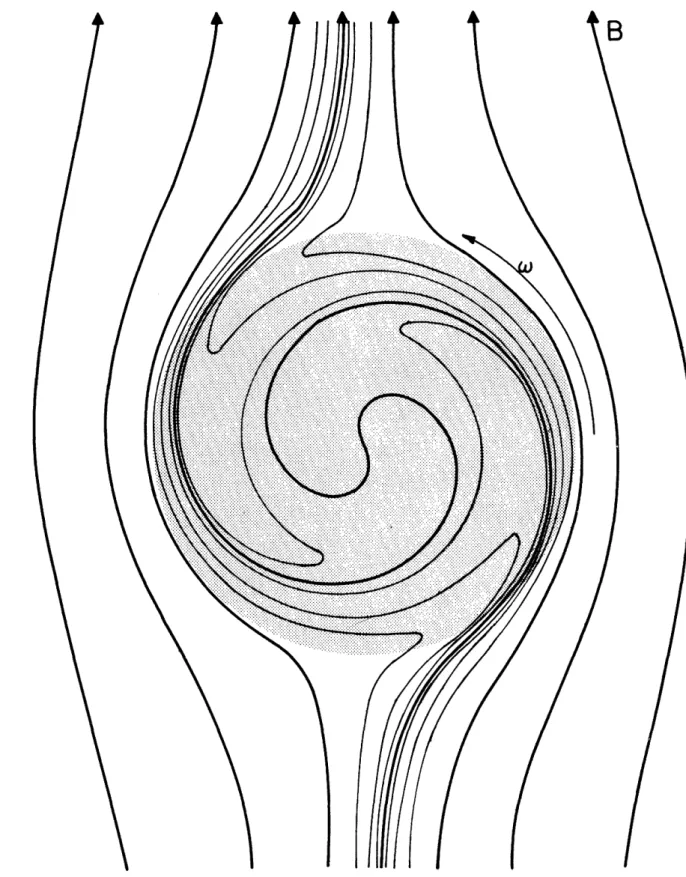
rd4Q r 4[64which determine the field pattern. Figures 2, 3, and 4 show plots for the typical cases po = ka = i, 2.5, and 10.
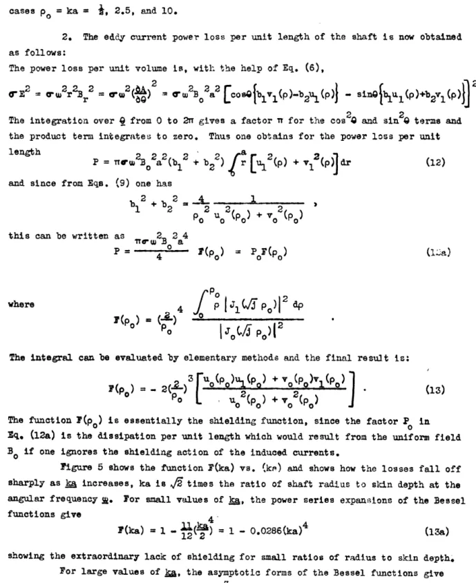
2. The eddy current power loss per unit length of the shaft is now obtained as follows:
The power loss per unit volume is, with the help of Eq. (6),
2 2
The integration over from 0 to 2 gives a factor n for the cos 0 and sin terms and the product term integrates to zero. Thus one obtains for the power loss per unit
length
2 2
2
2
A 2 2length= TTW 02a2(b1 + b2 2
) r [U1 (p) + 1 ()] dr (12) and since from Eqs. (9) one
has
b12 + b22 4
P
ou2(Po)
+Vo
2p)
this can be written as 2 2a4
4-
1(Po
)=
PoS(Po)
(ma)
PO
where
4
4
jPJ
i
1(JP
po)l
)2
dp(po
)=
)
0=2
-;
The integral can be evaluated by elementary methods and the final result is:
F(p) 2(-)
r (p)ul(p)
+
0o)Vl(p
>(13)
F()
2
u-p)+
p)
The function (po) is essentially the shielding function, since the factor Po in Eq. (12a) is the dissipation per unit length which would result from the uniform field Bo if one ignores the shielding action of the induced currents.
Figure 5 shows the function F(ka) vs. (ke) and shows how the losses fall off sharply as ka increases, ka is A/~ times the ratio of shaft radius to skin depth at the
angular frequency ~. For small values of ka, the power series expansions of the Bessel functions give
F(ka) = 1 1- 0.0286(ka)4 (13a)
12 2
showing the extraordinary lack of shielding for small ratios of radius to skin depth. For large values of ja, the asymptotic forms of the Bessel functions give
'(ka)-,J
(i)
as ka-
o
.
(13b)
Thus for large ratios of radius to skin depth, E. (12a) gives for the power loss per unit length 2
P 2rrA f= f '
-4-A
B
Figure 2. Magnetic field pattern for p = ka O.Z where k = 6/ and a = shaft radius. The shaded area represents tie cross section of the rotating shaft.
I_
_
I
A
1
B
t
I
Figure 3. Magnetic field pattern for p = ka = 2.5 where k = 4o; and a = shaft radius. The shaded area represents te cross section of the rotating shaft.
-6-I
_I
_
Figure 4. Magnetic field pattern for p = ka = 10 where k = Ib and a = shaft radius. The shaded area represents tRe cross section of the otating shaft. The heavy lines correspond to uniformly spaced lines of B . The lighter lines are
inserted to show the detailed behavior of the feld inside the shaft.
-7---
- --
O) oi -00 0 z a -J iL-L
0
a
>.a:
a. z
4 W I a<
zw
U) ( ) Li cn n o Ctoloo
o o 0 b bj 3 bP a I Y 1o 0 11 0 JAC N0)o
O
v
t
t
o
8
t t o o Y t -i z cc w X : 0 IL w 0cr
U.o
I-JD
0 -iIc
O0 O ZC) C) 0 -J 0 I-0 .w
Qz !.-0 Ct < 1Io.Io~p
CD U) n0 N1afio
-8-n II 1I3. In
the case of a shaft of permeability ~L
N
,
assumed constant, we must
have
continuity of
and
f
A at r - a (p =
). Prom Eq. (6) one then
finds the
following values of the constants in place of Eq. 9).
Po
-0-
PFO
+ PO1 = 1
u O+uV2
% ' PoV_-
o_-
2
P
%
o
PO Uo
0
,
,
b2 2 2r t
Po u
00
pOO
0 2ti-+bv
2
(9a)
2
Po,
1 Po - 0 2 _ 22~(2
02-v
1
+
2
v
il)
where
the constants
u
o, u
1, Vo,
and v
1are the values of the functions at p
Po.
The
eddy current loss
per unit length and the equations for the lines of B may then be
obtained by using the constants given by (9a) in Eqs. (12) and (6).
A


