Dynamic Fluid#Like Graphene with
Ultralow Frictional Molecular Bearing
The MIT Faculty has made this article openly available. Please share
how this access benefits you. Your story matters.
Citation Intak, Jeon et al. "Dynamic Fluid#Like Graphene with Ultralow Frictional Molecular Bearing." Advanced Materials 31, 43 (September 2019): 1903195 © 2019 Wiley
As Published http://dx.doi.org/10.1002/adma.201903195
Publisher Wiley
Version Author's final manuscript
Citable link https://hdl.handle.net/1721.1/128131
Terms of Use Creative Commons Attribution-Noncommercial-Share Alike
DOI: 10.1002/((please add manuscript number))
Article type: Communication
Dynamic Fluid-like Graphene with Ultra-Low Frictional Molecular Bearing
Intak Jeon1,2†, Geehoon Park3†, Pan Wang1,2, Ju Li4,5*, Ian W. Hunter3*, and
Timothy M. Swager1,2*
Dr. I. Jeon, Dr. P. Wang, Prof. T. M. Swager Department of Chemistry
Institute for Soldier Nanotechnologies Massachusetts Institute of Technology Cambridge, MA 02139, USA
E-mail: [email protected] G. Park, Prof. I. W. Hunter
Department of Mechanical Engineering Massachusetts Institute of Technology Cambridge, MA 02139, USA
E-mail: [email protected] Prof. J. Li
Department of Nuclear Science and Engineering Department of Materials Science and Engineering Massachusetts Institute of Technology
Cambridge, MA 02139, USA E-mail: [email protected]
†These authors contributed equally to this work.
Keywords: fluid-like graphene, ultra-low friction, molecular bearing, coefficient of friction of
0.01, triptycene
Abstract: Fluid-like sliding graphenes but with solid-like out-of-plane compressive rigidity
offer unique opportunities for achieving unusual physical and chemical properties for next generation interfacial technologies. Of particular interest in the present study are graphenes with specific chemical functionalization that can predictably promote adhesion and wetting to substrate and ultra-low frictional sliding structures. We experimentally demonstrate lubricity between stainless steel (SS) and diamond-like-carbon (DLC) with densely functionalized graphenes displaying dynamic intersheet bonds that mechanically transform into stable tribolayers. The macroscopic lubricity evolves through the formation of a thin film of an interconnected graphene matrix that provides a coefficient of friction (COF) of 0.01.
Revised Manuscript 1 2 3 4 5 6 7 8 9 10 11 12 13 14 15 16 17 18 19 20 21 22 23 24 25 26 27 28 29 30 31 32 33 34 35 36 37 38 39 40 41 42 43 44 45 46 47 48 49 50 51 52 53 54 55 56 57 58 59 60
Mechanical sliding generates complex folded graphene structures wherein equilibrated covalent chemical linkages impart rigidity and stability to the films examined in macroscopic friction tests. This new approach to frictional reduction has broad implications for manufacturing, transportation, and aerospace.
Article
The development of advanced superlubricant materials, defined by a coefficient of friction (COF) near or lower than 0.01, is essential for the sustainability and achieving higher performance from mechanical devices.[1-3] Although pristine graphene has a desirable
incommensurability in its lattice plane relative to other materials and can suppress mechanical wear,[4-9] the creation of incommensurate stable contacts at macroscale interfaces still poses
fundamental challenges. In particular, superior lubricant materials will have both the properties of a liquid and a solid.[10-14] At one extreme, a thin layer of a liquid (water) can
behave as a lubricant, and hydroplaning behavior reduces frictional contact between tires and a road.[15] Inspired by hydroplaning and graphite, we have designed a fluid-like reconfigurable
graphene matrix that shows quasi-hydrodynamic and ultra-low frictional behavior. We hypothesized that the graphene matrix with chemically dynamic (reversible) connections can transform into molecular bearings that simultaneously have a large resistance to further compression and a stable top-surface with sustained lubricity with ultra-low friction.
To create a scalable ultra-low frictional material, we designed a coating wherein basal plane functionalized graphenes, produced by electrochemical activation, are covalently attached to structurally rigid triptycene molecular cores. Specifically the interconnected graphene matrix is produced by the reactive formation of Meisenheimer complexes between graphene functionalized with 3,5-dinitrophenyl groups and triaminotriptycene
(Triamino-T).[16, 17] Triamino-T was designed as a highly stable rigid 3D interlocking group that
1 2 3 4 5 6 7 8 9 10 11 12 13 14 15 16 17 18 19 20 21 22 23 24 25 26 27 28 29 30 31 32 33 34 35 36 37 38 39 40 41 42 43 44 45 46 47 48 49 50 51 52 53 54 55 56 57 58 59 60
reversibly covalently links reactive functionalized graphenes into an interconnected matrix that is dynamically configured by physical sliding motions. The COF of the resultant triaminotriptycene functionalized graphene (FG-T) reaches the ultra-low regime (0.01), whereas graphene functionalized with 3,5-dinitrophenyl groups, but lacking Triamino-T modification, shows a higher and erratic friction as a result of chemical interactions with the interacting surfaces. The 3,5-dinitrophenyl functionalized graphene is reacted with
Triamino-T to give a material (FG-Triamino-T+) that evolves into stable self-leveling tribo-layers during sliding.
The structural re-arrangement of the graphene matrix provides a mechanism to achieve robust superlubricity at both the micro- and macro-scale.
The FG-T+ composition (Figure 1a and Figure S1) undergoes reversible Meisenheimer complexation reactions that provide a reconfigurable interlocking component. Here the NH2 groups of the Triamino-T can be bonded to up to three different
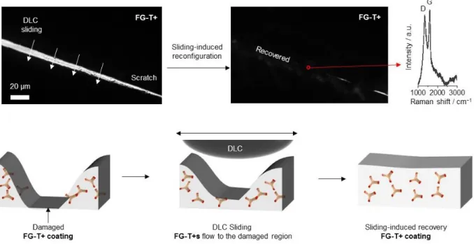
3,5-dinitrophenyl groups, and the stoichiometry of FG-T+ ensures residual reactive primary amines (Figure S2). The FG-T+ film structure equilibrates through transient chemical configurations when mechanical shearing (sliding motion) is applied to the material. The reversible reconfiguration of the films under sliding against a DLC-coated ball further enables self-leveling (recoating) of damaged regions (Figure S3), which demonstrate strong adhesion and "complete wetting" between FG-T+ and steel substrate. The final matrix contains a highly crosslinked FG-T network with 3D rigid triptycene interlocking units between graphene sheets bond in Meisenheimer complexes (Figure 1a).[18] We postulate that the
FG-T+ film is segmented into viscous films on the top-surfaces, and a core connection to the
substrate through the elastic graphene matrix. These layers help to induce viscous flow on top-surface and to guard against wear, thereby producing quasi-hydrodynamic behavior with reduced fiction.[19] 1 2 3 4 5 6 7 8 9 10 11 12 13 14 15 16 17 18 19 20 21 22 23 24 25 26 27 28 29 30 31 32 33 34 35 36 37 38 39 40 41 42 43 44 45 46 47 48 49 50 51 52 53 54 55 56 57 58 59 60
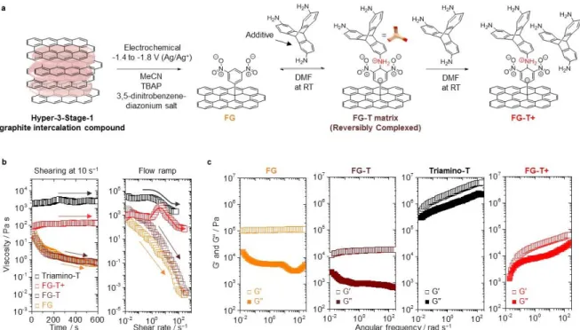
The solid 3,5-dinitrophenyl functionalized graphene (FG) film shows transient shear thinning behavior (Figure 1b). Conversely, dynamic linkages of FG-T+ lead to Newtonian fluid-like behavior, perhaps promoted by the equilibrating Meisenheimer complexation and the associated changes in graphene structure (Figure 1b). The addition of excess Triamino-T lowers the viscosity from the beginning shear rate of 5.0 s−1, and this behavior for the FG-T+
films is consistent with energy dissipation as a result of dynamic rearrangement of the Meisenheimer complexes (Figure 1b).[20, 21]
To further probe viscoelastic properties of these reversible and reconfigurable complexes we have determined the storage modulus (G′) and loss modulus (G′′) at different frequencies of oscillating strain. FG and FG-T show a predominant elastic response over the entire frequency range (G′ >> G′′), whereas the viscoelastic behavior of FG-T+ shows continuous changes over the frequency spectrum investigated (Figure 1c). In case of FG, we note that the decrease in the loss modulus at 7 rad s−1 is consistent with chemical degradation,
wherein continuous shearing induces mechanochemical reactions on graphene. Subsequent mechanochemical damage or physical removal of material, results in further change the loss modulus contribution during shearing (vide infra). The gradual increases in the viscoelastic response of the FG-T+ film is consistent with our proposed chemical/structural evolution that occurs without chemical degradation. In total the rheological results are self-consistent with reversible Meisenheimer complex formation between the triptycenes and graphene to give a fluid-like matrix for reducing frictional behavior. These mechanical dynamics offer insights into the kinetics of the reconfigurable bonding in functional graphenes.
1 2 3 4 5 6 7 8 9 10 11 12 13 14 15 16 17 18 19 20 21 22 23 24 25 26 27 28 29 30 31 32 33 34 35 36 37 38 39 40 41 42 43 44 45 46 47 48 49 50 51 52 53 54 55 56 57 58 59 60
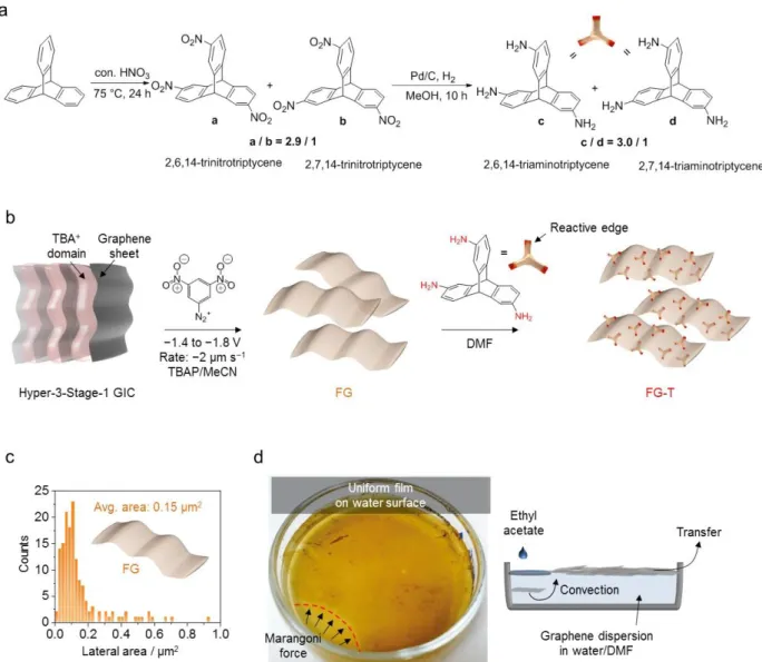
Figure 1. Fluid-like reconfigurable graphene. (a) Synthesis and chemical structures of FG, FG-T, and FG-T+. FG-T is synthesized via Meisenheimer complexes reaction with Triamino-T. FG-T+ contains the additional concentration of Triamino-T (additive) such that there are free amine groups that are not covalently linked to the graphene. MeCN: acetonitrile, TBAP: tetrabutylammonium perchlorate and DMF: dimethylformamide. (b) Time-dependent viscoelastic behaviors of FG, FG-T, Triamino-T, and FG-T+: Shearing at the shear rate of 10 s−1 for 10 mins. The FG and FG-T continuously decrease in viscosity
with increased shear rate. The viscosity–shear strain rate curves: Triamino-T (black arrow) show shear thinning behaviors. After reconfiguration (red arrow), the FG-T+ stabilizes and approaches a Newtonian behavior because the graphene matrix with triptycenes can rearrange to accommodate stress. (c) Linear viscoelastic behavior: Change in storage (G′) and loss (G′′) moduli versus angular frequency (ω) with the strain of γ = 0.5% for FG, FG-T, FG-T+ and
Triamino-T, demonstrating the reconfigurable viscoelastic mechanism of the FG-T+ matrix. 1 2 3 4 5 6 7 8 9 10 11 12 13 14 15 16 17 18 19 20 21 22 23 24 25 26 27 28 29 30 31 32 33 34 35 36 37 38 39 40 41 42 43 44 45 46 47 48 49 50 51 52 53 54 55 56 57 58 59 60
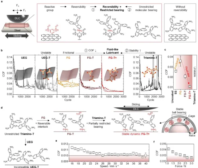
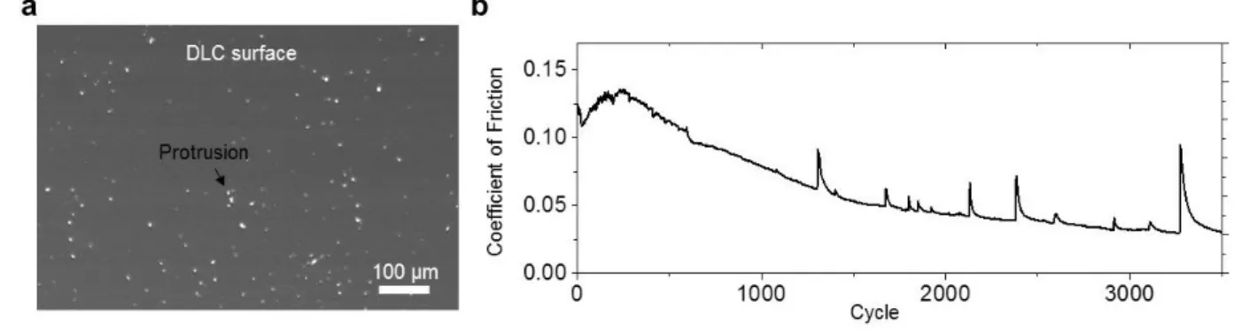
Friction tests were conducted by coating stainless steel (SS) with the different graphenes and sliding a diamond like carbon (DLC) coated SS ball, using a custom-built linear macro-tribometer (Figure 2a and Figure S4). Initially, the COF of unfunctionalized exfoliated low defect graphene (UEG) is ~0.022 (Figure 2b), a value comparable to the previously reported graphenes and graphene oxides (GOs), thereby confirming the system’s performance (Figure S5).[22-24] The UEG is produced from a dimethylformamide dispersion
of a Hyper-3-Stage-1 graphite intercalation compound (GIC),[16] and although it forms a low
frictional tribo-layer, the stability of the tribo-layer on the SS substrate was not satisfactory, as it easily peels off or ball up on the substrate, showing poor adhesion and incomplete wetting. To create a stable layer, the coating materials need to remain strongly associated with the surface during mechanical movement (Figure S6). In case of UEG coatings on the SS substrate, large spikes in the COF ~ 0.1 appear by about 1500 cycles, indicating removal of graphene tribo-layer as a result of weak adhesion to the substrate (Figure 2b). These spikes appear at random intervals, are frequency and magnitude dependent, and are a signature of insufficient adhesion to the SS surface (Figure S7). The high contact pressures and linear motion give rise to a natural gradual loss of graphene coverage from metallic substrates in macroscopic friction tests. As a result, graphene tribo-layers can undergo detrimental transformations in very short periods. These adhesion challenges are the reason that typical multilayer graphene systems, which are nominally expected to have the low frictional properties, fail to provide stable superlubricity.[7]
FGs in general have enhanced interactions with most substrate materials and hence
have utility for increasing the stability of a tribofilm (Figure 2b). However, the high COF observed for the FG used in this study appears to produce adhesive interactions between contacting materials, but without special additives, this material degrades and does not produce stable tribofilms in the friction tests. These results are consistent with previous
1 2 3 4 5 6 7 8 9 10 11 12 13 14 15 16 17 18 19 20 21 22 23 24 25 26 27 28 29 30 31 32 33 34 35 36 37 38 39 40 41 42 43 44 45 46 47 48 49 50 51 52 53 54 55 56 57 58 59 60
atomic force microscopy (AFM) friction measurements on fluorinated graphene,[25, 26]
wherein functionalized graphene monolayers exhibited higher friction forces relative to pristine graphene. In short, the friction originates from basal plane functional groups that increase van der Waals interactions. To overcome these seemingly intrinsic limitations associated with functionalized graphene, we targeted the generation of dynamic nanostructures to realize a stable ultra-low frictional state.
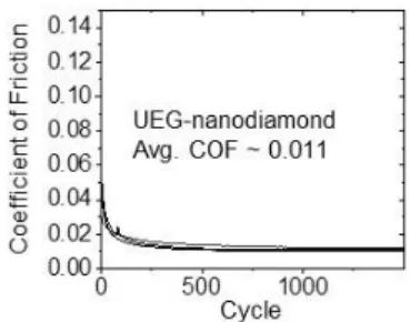
The FG-T matrix relaxes under applied stress through reversible chemical bonding events with Triamino-T. We observed the further reduction in COFs with FG-T+, which produces an ultra-low frictional state (Figure 2b and c) comparable to UEG-nanodiamond combinations (Figure S8).[22] We attributed this result to the reconfiguration of the stable
graphene matrix, wherein the molecular crosslinker connects graphene surfaces and stabilizes bilayers and/or folded structures to create dynamic “molecular-bearings” with mechanical stiffness and stability (Figure 2d and Figure S9). This process gives a dense stable tribo-layer with liquid-like properties that allows for self-leveling of the lubricant tribo-layer, to counteract the continuous mechanical removal caused by the sliding and pressure gradient. In contrast to FG-T/FG-T+, the mixture of UEG and Triamino-T (UEG-T) exhibits unstable sliding behavior due to the lack of the chemical function for stabilizing bearing molecules (Figure 2b and d). The friction coefficient of FG-T+ stabilizes at 0.011 at 16 mm s−1 and
drops to 0.01 at 26 mm s−1 (Figure 2e). The FG-T+ also shows low frictional behavior (COF
< 0.015) at loads varying from 3 N to 1.1 N (Figure 2f). After long-term cycles, we observed the lower wear rate of DLC-coated SS ball against a FG-T+ (0.94 10−9 mm3 N−1 m−1) on SS
as compared to uncoated SS (9.94 10−9 mm3 N−1 m−1) (Figure S10). FG-T+ also
outperformed an uncoated SS in ambient air and initially showed reduced friction for a SS/SS pair (Figure S11). 1 2 3 4 5 6 7 8 9 10 11 12 13 14 15 16 17 18 19 20 21 22 23 24 25 26 27 28 29 30 31 32 33 34 35 36 37 38 39 40 41 42 43 44 45 46 47 48 49 50 51 52 53 54 55 56 57 58 59 60
Figure 2. Illustration of COF and results for graphene films. (a) Schematic illustration
showing the geometry of a linear tribometer equipped with a DLC-coated stainless steel ball. The friction tests were performed with graphenes and/or Triamino-T to demonstrate the synergetic coupling effect of reversible Meisenheimer complexes and molecular bearings. (b) The COF for a DLC ball sliding at 16 mm s−1 and a contact pressure of 0.3 ~ 0.4 GPa, against
UEG (COF ~ 0.022 ± 0.003), UEG-T (COF: unstable), FG (COF ~ 0.036 ± 0.005), FG-T
(COF ~ 0.021 ± 0.002), FG-T+ (COF ~ 0.011 ± 0.001) and Triamino-T (COF: unstable) films on a SS substrate in N2 environment (relative humidity: ~ 3 %). Friction experiments
were repeated three or more times for each sample (one cycle = two linear-sliding motions). (c) The average COF of the uncoated SS, FG, FG-T, FG-T+ and Triamino-T films. (d) The proposed dynamic model of reversible Meisenheimer complexation of graphene with
Triamino-Ts to create reconfigurable networks “bearing” behavior. First, unrestricted Triamino-T shows unstable sliding motion with temporary low COF in our system. Second,
the incompatibility of UEG-T restricts the formation of a stable matrix during sliding. Third, the molecular bearing motion of partially restricted Triamino-T is effectively stabilized in a dynamic FG-T/FG-T+ matrix, maintaining low COF. (e) The FG-T+ friction with increasing sliding speed tests from 16 mm s−1 to 40 mm s−1 with ≈ 0.01 above a 26 mm s−1 sliding speed
in the quasi-hydrodynamic lubrication regime. (f) Load dependency of the COF of FG-T+.
1 2 3 4 5 6 7 8 9 10 11 12 13 14 15 16 17 18 19 20 21 22 23 24 25 26 27 28 29 30 31 32 33 34 35 36 37 38 39 40 41 42 43 44 45 46 47 48 49 50 51 52 53 54 55 56 57 58 59 60
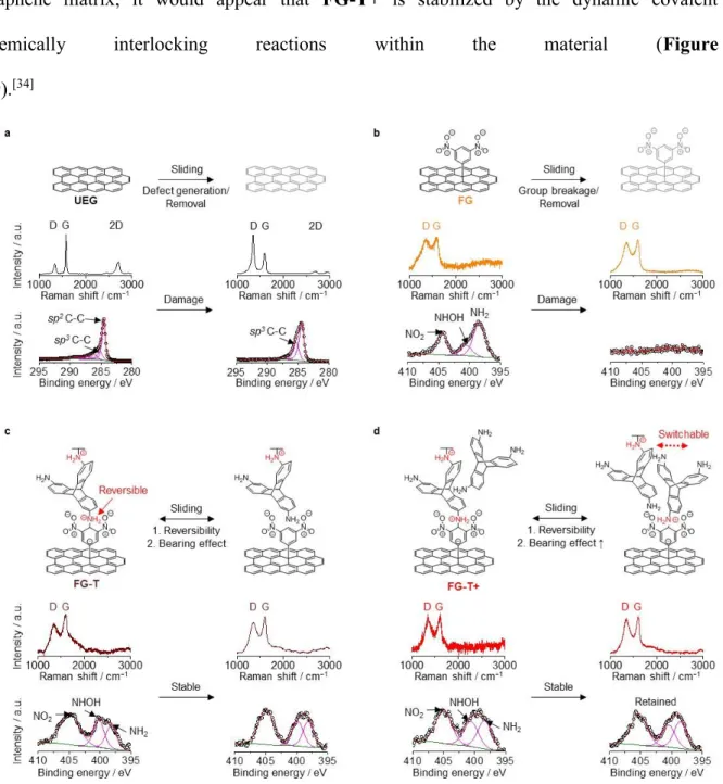
To gain insight on the tribochemical reactions and how FG-T and FG-T+ promote stable ultra-low frictional states, we have conducted Raman and XPS analyses of the as deposited materials and the mechanically produced tribo-layers (Figure 3 and Figure S12).[16, 27, 28] In general, graphenes slip by each other and then evolve into graphene tribo-layers with
the reduced COF against the DLC-coated ball.[7, 29] The final state of graphene on a SS
substrate after sliding can produce changes in the Raman 2D and D-bands, which are quantified by the D-band to the G-band ratio, ID/IG. An increasing ID/IG indicates the
introduction of defects in the graphene layers (Figure 3a), and this is readily apparent for
UEG. In addition, the G-band (1591 cm−1) for the lubricated graphene shifts after sliding,
compared with that of pristine graphene (1580 cm−1), which also indicates changes in
chemical or physical state. [16, 30] This is expected as the G-band is sensitive to damage
within the graphene sheets. Additionally, XPS analysis reveals increases in the relative ratios of sp3 C−C (~285.5 eV) to sp2 C−C peaks (~284.5 eV), which is also an indication of
mechanically induced chemistry (Figure 3a).
FG initially has a high density of pendant groups (Raman ID/IG ratio ~0.93 in Figure
3b) with a stronger interaction with the DLC surface and a higher frictional resistance toward
sliding. The nitrogen-containing functional groups are removed with sliding (Figure 3b) and the XPS N 1s signals associated with functional groups on the surface of graphene are not detectable after sliding. However, the XPS signals associated with sp3 carbons (~285.5 eV)
and the Raman ID/IG remains high (Figure 3b and Figure S9). The fate of removed nitrogen
containing functional groups and the nature of the sp3 Cs are not known, however
mechanochemical reactions are expected under the applied load.[26, 31-33]
The addition of the triptycene stabilizes the 3,5-dinitrophenyl groups on the graphene and in contrast to FG the XPS N 1s signals associated with the 3,5-dinitrophenyl functional groups of FG-T and FG-T+ are retained after sliding (Figure 3c and d). Although it is a
1 2 3 4 5 6 7 8 9 10 11 12 13 14 15 16 17 18 19 20 21 22 23 24 25 26 27 28 29 30 31 32 33 34 35 36 37 38 39 40 41 42 43 44 45 46 47 48 49 50 51 52 53 54 55 56 57 58 59 60
challenge to experimentally probe the precise physical and chemical interior states of the graphene matrix, it would appear that FG-T+ is stabilized by the dynamic covalent chemically interlocking reactions within the material (Figure
S9).[34]
Figure 3. Mechanically induced chemical transitions of graphene films. Raman and XPS
spectra of (a) UEG, (b) FG, (c) FG-T, and (d) FG-T+ before and after sliding cycles that detail characteristic changes. The tribo-layer of fluid-like FG-T+ is stabilized during sliding motion due to the reversibility of FG-T+ into contacting edges and self-leveling. The solid-like FG and UEG undergo tribo-chemically damage as evidenced by changes in their spectral properties. 1 2 3 4 5 6 7 8 9 10 11 12 13 14 15 16 17 18 19 20 21 22 23 24 25 26 27 28 29 30 31 32 33 34 35 36 37 38 39 40 41 42 43 44 45 46 47 48 49 50 51 52 53 54 55 56 57 58 59 60
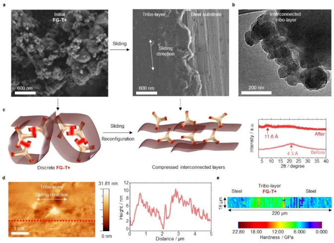
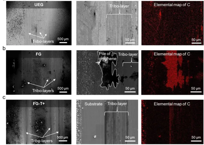
Tribo-layers are produced after sliding tests as shown in Figure 4. Scanning electron microscope (SEM) images (Figure 4a and Figure S6) reveal that with frictional testing the graphene is partially removed and reconfigured. The formation of a stable surface-bonded tribo-layer at a contacting surface reduces wear by minimizing contact of material pairs.[35]
Our lubricant with its quasi-hydrodynamic nature, is initially in a form that can be characterized as crumpled graphene nanoballs. The mechanical sliding under load then leads to a coalescence of particles to produce continuous solid lubricant film that strongly adheres to and completely wets the substrate. The very rigid framework within these films results from the interlinking of graphenes by Meisenheimer complexation.
To observe the structural progression of our graphene lubricant, we performed microstructure and surface analyses of tribo-layers after sliding using transmission electron microscopy (TEM) and atomic force microscopy (AFM) (Figure 4 and Figure S13).[36-38] As
shown in Figure 4b, that graphenes initially appear as a continuous interconnected material (Figure 4b). During sliding at a stress of 0.4 GPa, the matrix undergoes compression and structurally evolves from a spherical configuration to compressed interconnected layers that have a spacing of 11.6 Å, which is consistent with the interlayer organic linkages (Figure 4c). The tribo-layer of FG-T+ produced by the sliding, is reasonably flat with ±5 nm surface features (Figure 4d and Figure S14), which is also consistent with a compressed layered structure. This planar tribo-layer allows DLC to slide and only encounter relatively small energetic barriers. The high out-of-plane rigidity of the FG-T+ tribo-layer is also critical and compares favorably to the bare SS (grade 316). Nanoindentation reveals a hardness with ~5.3 GPa for the SS 316 substrate and ~7.3 GPa for the tribo-layer of FG-T+ (Figure 4e). The higher value of hardness is also consistent with a strongly textured FG-T+ tribo-layer.
1 2 3 4 5 6 7 8 9 10 11 12 13 14 15 16 17 18 19 20 21 22 23 24 25 26 27 28 29 30 31 32 33 34 35 36 37 38 39 40 41 42 43 44 45 46 47 48 49 50 51 52 53 54 55 56 57 58 59 60
Figure 4. The representative microstructure of FG-T+ matrix after sliding. (a) SEM
image of as-prepared FG-T+ before sliding and the tribo-layer after sliding. (b) TEM image of the tribo-layer of FG-T+. The formation of continuous FG-T+ matrix is observed. (c) Left:
as-prepared FG-T+ matrix is proposed to be in a compacted folded structure. Right: After its
sliding test FG-T+ is expected to have more of a compressed bi/multi-layer structure, which is supported X-ray diffraction data. (d) Tapping-mode AFM topology image of the top-surface of the tribo-layer. The AFM height profile measured along the red dashed line. The tribo-layer of FG-T+ has a flattened surface. (e) A nanoindentation map displays the hardness of the representative FG-T+ tribo-layer, using a Berkovich diamond indenter.
In summary, we have demonstrated that FG-T+ forms a fluid-like graphene matrix that produce stable tribo-layers and a low frictional force against the DLC (COF ~ 0.01). The dynamic reactivity and flexibility of functional graphene and the rigid frame of triptycene combine to produce adherent and shearing structures under compressive sliding deformation.
This approach to an ultra-low frictional state is potentially generalizable and is an important step to understanding how to control friction at the macroscale.
1 2 3 4 5 6 7 8 9 10 11 12 13 14 15 16 17 18 19 20 21 22 23 24 25 26 27 28 29 30 31 32 33 34 35 36 37 38 39 40 41 42 43 44 45 46 47 48 49 50 51 52 53 54 55 56 57 58 59 60
Supporting Information
Supporting Information is available from the Wiley Online Library or from the author.
Acknowledgements
T. Swager, J. Li, and I. Hunter directed the project. I. Jeon synthesized graphene materials and G. Park constructed the friction measurement apparatus. I. Jeon and G. Park carried out experiments and the data analysis. P. Wang synthesized triamimotriptycene. All the authors discussed the results and contributed to the writing of the manuscript. I. Jeon and G. Park contributed equally to this work. This work was supported by the US Army Research Office through the use of facilities at the Institute for Soldier Nanotechnologies under Contract Number W911NF-13-D-0001 and National Science Foundation, DMR-1809740. We appreciate Maggie He for synthesizing the 3,5-dinitrobenzenediazonium salt.
Received: ((will be filled in by the editorial staff)) Revised: ((will be filled in by the editorial staff)) Published online: ((will be filled in by the editorial staff))
References
[1] S. C. Tung, M. L. McMillan, Tribol. Int. 2004, 37, 517.
[2] K. Holmberg, P. Andersson, A. Erdemir, Tribol. Int. 2012, 47, 221. [3] S. F. Tie, C. W. Tan, Renew. Sust. Energ. Rev. 2013, 20, 82.
[4] C. Lee, Q. Y. Li, W. Kalb, X. Z. Liu, H. Berger, R. W. Carpick, J. Hone, Science
2010, 328, 76.
[5] S. Kawai, A. Benassi, E. Gnecco, H. Sode, R. Pawlak, X. L. Feng, K. Mullen, D. Passerone, C. A. Pignedoli, P. Ruffieux, R. Fasel, E. Meyer, Science 2016, 351, 957.
[6] M. Dienwiebel, N. Pradeep, G. S. Verhoeven, H. W. Zandbergen, J. W. M. Frenken,
Surf. Sci. 2005, 576, 197.
[7] S. Z. Li, Q. Y. Li, R. W. Carpick, P. Gumbsch, X. Z. Liu, X. D. Ding, J. Sun, J. Li,
Nature 2016, 539, 541.
[8] M. S. Won, O. V. Penkov, D. E. Kim, Carbon 2013, 54, 472.
[9] Y. Z. Qi, J. Liu, J. Zhang, Y. L. Dong, Q. Y. Li, ACS Appl. Mater. Inter. 2017, 9, 1099.
[10] I. R. Peters, S. Majumdar, H. M. Jaeger, Nature 2016, 532, 214.
[11] V. Trappe, V. Prasad, L. Cipelletti, P. N. Segre, D. A. Weitz, Nature 2001, 411, 772. [12] X. Cheng, J. H. McCoy, J. N. Israelachvili, I. Cohen, Science 2011, 333, 1276. [13] J. M. Brader, J Phys-Condens Mat 2010, 22, 363101.
[14] J. Vermant, M. J. Solomon, J Phys-Condens Mat 2005, 17, R187.
[15] D. Mohrig, K. X. Whipple, M. Hondzo, C. Ellis, G. Parker, Geol Soc Am Bull 1998,
110, 387.
[16] I. Jeon, B. Yoon, M. He, T. M. Swager, Adv. Mater. 2018, 30, 1704538. [17] T. M. Swager, Acc. Chem. Res. 2008, 41, 1181.
[18] F. Terrier, Chem. Rev. 1982, 82, 77. [19] H. Heshmat, Lubr Eng 1992, 48, 373.
[20] F. Del Giudice, A. Q. Shen, Curr Opin Chem Eng 2017, 16, 23.
[21] S. B. Kharchenko, J. F. Douglas, J. Obrzut, E. A. Grulke, K. B. Migler, Nat. Mater.
2004, 3, 564.
[22] D. Berman, S. A. Deshmukh, S. K. R. S. Sankaranarayanan, A. Erdemir, A. V. Sumant, Science 2015, 348, 1118. 1 2 3 4 5 6 7 8 9 10 11 12 13 14 15 16 17 18 19 20 21 22 23 24 25 26 27 28 29 30 31 32 33 34 35 36 37 38 39 40 41 42 43 44 45 46 47 48 49 50 51 52 53 54 55 56 57 58 59 60
[23] K. S. Kim, H. J. Lee, C. Lee, S. K. Lee, H. Jang, J. H. Ahn, J. H. Kim, H. J. Lee, ACS
Nano 2011, 5, 5107.
[24] D. Berman, A. Erdemir, A. V. Sumant, Mater. Today 2014, 17, 31.
[25] Q. Y. Li, X. Z. Liu, S. P. Kim, V. B. Shenoy, P. E. Sheehan, J. T. Robinson, R. W. Carpick, Nano Lett. 2014, 14, 5212.
[26] S. Kwon, J. H. Ko, K. J. Jeon, Y. H. Kim, J. Y. Park, Nano Lett. 2012, 12, 6043. [27] M. J. Webb, P. Palmgren, P. Pal, O. Karis, H. Grennberg, Carbon 2011, 49, 3242. [28] E. Bekyarova, M. E. Itkis, P. Ramesh, C. Berger, M. Sprinkle, W. A. de Heer, R. C. Haddon, J. Am. Chem. Soc. 2009, 131, 1336.
[29] X. F. Feng, S. Kwon, J. Y. Park, M. Salmeron, ACS Nano 2013, 7, 1718.
[30] O. Frank, G. Tsoukleri, J. Parthenios, K. Papagelis, I. Riaz, R. Jalil, K. S. Novoselov, C. Galiotis, ACS Nano 2010, 4, 3131.
[31] S. L. James, C. J. Adams, C. Bolm, D. Braga, P. Collier, T. Friscic, F. Grepioni, K. D. M. Harris, G. Hyett, W. Jones, A. Krebs, J. Mack, L. Maini, A. G. Orpen, I. P. Parkin, W. C. Shearouse, J. W. Steed, D. C. Waddell, Chem. Soc. Rev. 2012, 41, 413.
[32] J. R. Felts, A. J. Oyer, S. C. Hernandez, K. E. Whitener, J. T. Robinson, S. G. Walton, P. E. Sheehan, Nat. Commun. 2015, 6, 6467.
[33] L. F. Wang, T. B. Ma, Y. Z. Hu, H. Wang, Phys. Rev. B 2012, 86, 125436. [34] A. D. Cambou, N. Menon, Proc. Natl. Acad. Sci. USA 2011, 108, 14741.
[35] N. N. Gosvami, J. A. Bares, F. Mangolini, A. R. Konicek, D. G. Yablon, R. W. Carpick, Science 2015, 348, 102.
[36] A. C. Ferrari, Solid State Commun. 2007, 143, 47.
[37] Q. Z. Wu, Y. P. Wu, Y. F. Hao, J. X. Geng, M. Charlton, S. S. Chen, Y. J. Ren, H. X. Ji, H. F. Li, D. W. Boukhvalov, R. D. Piner, C. W. Bielawski, R. S. Ruoff, Chem. Commun.
2013, 49, 677.
[38] A. C. Ferrari, J. C. Meyer, V. Scardaci, C. Casiraghi, M. Lazzeri, F. Mauri, S. Piscanec, D. Jiang, K. S. Novoselov, S. Roth, A. K. Geim, Phys. Rev. Lett. 2006, 97, 187401.
1 2 3 4 5 6 7 8 9 10 11 12 13 14 15 16 17 18 19 20 21 22 23 24 25 26 27 28 29 30 31 32 33 34 35 36 37 38 39 40 41 42 43 44 45 46 47 48 49 50 51 52 53 54 55 56 57 58 59 60
Fluid-like graphene shows macroscopic lubricity reaching a coefficient of friction of 0.01.
The rigid 3D molecular interlocking groups (Molecular bearing: triaminotriptycene, additive) create nanostructures by bonding (Stabilizer: Meisenheimer complexation) to the 3,5-dinitrophenyl functionalized graphene. Mechanical shearing converts these graphene composites into highly stable surface bound tribo-layers with a coefficient of friction (COF) ~ 0.01.
Keyword: fluid-like graphene, ultra-low friction, molecular bearing, coefficient of friction of
0.01, triptycene
Intak Jeon1,2†, Geehoon Park3†, Pan Wang1,2, Ju Li4,5*, Ian W. Hunter3*, and Timothy M.
Swager1,2*
Dynamic Fluid-like Graphene with Ultra-Low Frictional Molecular Bearing 1 2 3 4 5 6 7 8 9 10 11 12 13 14 15 16 17 18 19 20 21 22 23 24 25 26 27 28 29 30 31 32 33 34 35 36 37 38 39 40 41 42 43 44 45 46 47 48 49 50 51 52 53 54 55 56 57 58 59 60
Copyright WILEY-VCH Verlag GmbH & Co. KGaA, 69469 Weinheim, Germany, 2016.
Supporting Information
Dynamic Fluid-like Graphene with Ultra-Low Frictional Molecular Bearing
Intak Jeon1,2†, Geehoon Park3†, Pan Wang1,2, Ju Li4,5*, Ian W. Hunter3*, and Timothy M.
Swager1,2*
Dr. I. Jeon, Dr. P. Wang, Prof. T. M. Swager Department of Chemistry
Institute for Soldier Nanotechnologies Massachusetts Institute of Technology Cambridge, MA 02139, USA
E-mail: [email protected] G. Park, Prof. I. W. Hunter
Department of Mechanical Engineering Massachusetts Institute of Technology Cambridge, MA 02139, USA
E-mail: [email protected] Prof. J. Li
Department of Nuclear Science and Engineering Department of Materials Science and Engineering Massachusetts Institute of Technology
Cambridge, MA 02139, USA E-mail: [email protected] 1 2 3 4 5 6 7 8 9 10 11 12 13 14 15 16 17 18 19 20 21 22 23 24 25 26 27 28 29 30 31 32 33 34 35 36 37 38 39 40 41 42 43 44 45 46 47 48 49 50 51 52 53 54 55 56 57 58 59 60
Materials and Methods
Synthesis of 3,5-dinitrophenyl functionalized graphene (FG): Highly oriented pyrolytic
graphite (HOPG) was used as the cathode in a three-electrodes electrochemical cell, containing 1.5 M tetrabutylammonium perchlorate (TBAP), acetonitrile (MeCN, 2 mL) and dimethylformamide (DMF, 2 mL) (Ag/Ag+ as reference electrode and graphite as counter
electrode). The application of continuous voltage ramp (−3.05 to −3.25 V as −2 μV s−1)
induced the intercalation of tetrabutylammonium cations (TBA+) into graphene interlayers,
resulting in Hyper-3-stage-1 graphite intercalation compound (GIC). Graphene and functionalized graphene dispersions were obtained by the following methods: (i) The Hyperstage-1 GIC was sonicated in DMF for exfoliation and then removal of the intercalated TBA+s was achieved by washing with MeCN and DMF. (ii) For covalent functionalization,
the Hyper-3-Stage-1 GIC was added carefully an electrochemical cell, containing 0.1 M 3,5-dinitrobenzenediazonium tetrafluoroborate, 1 M TBAP and 4 mL MeCN solution. Again, continuous voltage ramp (−1.40 to −1.80 V as −2 μV s−1) was passed through the
Hyper-3-Stage-1 GIC. FGs were spontaneously exfoliated from the Hyper-3-Hyper-3-Stage-1 GIC. Then the functionalized graphene sheets were collected through vacuum filtration and thoroughly washed with MeCN and DMF.
Synthesis of Trinitrotriptycenes a and b (Figure S1): Triptycene (2.0 g, 8 mmol) and
concentrated HNO3 (80 mL) were added in a round flask. The mixture was heated to 75 °C for
24 h. After cooling down to room temperature, the solution was poured into ice water. The precipitate was filtered, washed with ice water and dried. The product was further purified by column chromatography to afford a and b as white solids (a/b = 2.9/1, 1.3 g, 42% yield). Compound a (major): 1H NMR (600 MHz, CDCl
3): δ 8.35-8.32 (m, 3H), 8.07-8.04 (m, 3H),
7.64-7.63 (m, 3H), 5.83 (s, 1H), 5.81 (s, 1H).
Synthesis of Triaminotriptycenes (Triamino-T) c and d (Figure S1): Trinitrotriptycenes a, b (1
g, 2.5 mmol) and MeOH (40 mL) were added in a flame-dried Schlenk flask. Palladium on activated charcoal was added to the solution, bubbling with hydrogen for 10 h. The mixture was then filtered through a pad of celite. The solvent was evaporated to give Triamino-T as yellow solids (c/d = 3.0/1, 0.73 g, 95% yield). Compound c (major): 1H NMR (600 MHz,
CDCl3): δ 7.07-7.04 (m, 3H), 6.73-6.71 (m,3H), 6.27-6.22 (m, 3H), 5.04 (s, 1H), 5.02 (s, 1H),
3.43 (br.s, 6H).
3,5-dinitrophenyl-triaminotriptycene functionalized graphene (FG-T): Figure S1 illustrates
the synthesis of the functionalized graphene with 3,5-dinitrophenyl groups anchoring triaminotriptycene groups. Meisenheimer complexes form by the addition of Triamino-T to the FG (50 mg : 4 mg weight ratio) in DMF. And then FG-T was collected through a polytetrafluoroethylene (PTFE) filter membrane with 0.1 µm pore size by vacuum filtration. FG-T+: 4 mg of Triamino-T was added to the above FG-T. For a stable sliding condition, the optimal weight ratio of FG/T is from 0.017 to 1.
Rheometric measurements of graphenes: Graphene dispersions were deposited on a substrate
and cut them to the appropriate size for rheometric tests. Graphenes were measured on a TA AR2000 rheometer in a 25-mm-diameter plate-plate geometry at 25 °C. Frequency sweeps were performed by applying a sinusoidal strain, γ = γ0sin(ωt), with γ0 = 0.5%, within the
linear viscoelastic range.
Graphene assembly: Graphene solutions were dispersed into DMF with the aid of sonication
to generate a uniform and stable graphene solution. The FG and FG-T+ solutions were
1 2 3 4 5 6 7 8 9 10 11 12 13 14 15 16 17 18 19 20 21 22 23 24 25 26 27 28 29 30 31 32 33 34 35 36 37 38 39 40 41 42 43 44 45 46 47 48 49 50 51 52 53 54 55 56 57 58 59 60
dispersed in DMF. These graphenes assembled into uniform films on the surface of water when several drops of ethyl acetate were added to the dispersion in dimethylformamide (DMF) that had been added to water (Figure S1). In this process the graphene moves to the water-air surface by Rayleigh-Bénard convection and then simultaneously assemble into an interconnected films driven by Marangoni forces. The film is then transferred onto a stainless steel (SS) substrate (Figure S1). After transfer, solvent is removed by vacuum evaporation at room temperature for 30 min. The SS plate samples were cleaned by sonication in acetone and isopropanol alcohol to remove any organic contaminants and then kept in a dry chamber. This densely covered surface was required to prevent the DLC from directly contacting the SS (grade 316) substrate.
Friction characterization: The friction measurement system, shown in Figure S4, consists of
a linear flexure bearing stage driven linearly back and forth by a custom built Lorenz force motor, two load cells connected in series and perpendicularly to each other, a stepper motor driving the sensor assembly up and down, and an environmental chamber in which the measurement system is enclosed. A reconfigurable input-output (cRIO) system (cRI0-9024, National Instruments) was used to control the velocity of the bearing stage and the normal force applied on the sample. To quantify COF (µ = Ff/Fn) the DLC ball slides back and forth
(linear velocity: 16 to 52 mm s−1) repeatedly along a horizontal line on a film, while
simultaneously measuring fictional force (Ff) and normal force (Fn). The resolutions of each
load cell are 5 mN (normal) and 0.5 mN (lateral), and forces are sampled at 1 kHz. 3 N of normal force was applied to the SS plate by moving the DLC-coated (a-C:H, Richter precision inc.) SS ball (grade 440C, diameter of 9.5 mm), attached at the tip of the sensor assembly, down to the sample on the moving bearing stage. The sample on the bearing stage slides 4 mm backward and forward against the DLC-coated SS ball and the linear velocity was maintained constant as 16 mm s−1 during the measurement. All measurements were conducted
at room temperature. The COF was calculated by dividing the measured frictional force by normal force and averaged over each backward and forward cycle to generate one data point on the COF plot. The first and the last 5 % of the measured COFs in each cycle were omitted as they reflect the static friction of the materials. Friction experiments were repeated more than three times for each sample in order to ensure the reliability. After the friction test, the tribo-layer on the wear track were collected to investigate the structure of films. To validate the accuracy of our custom built friction measurement setup, the friction coefficient of stainless steel ball (grade 440C, diameter of 9.5 mm) against a Teflon sheet (thickness of 0.9 mm) is measured and compared to data presented in other literature[1,2] (see Figure S5). The
sliding speed of the experiments is 2.5 mm s−1 and normal force of 1.5 N, 3 N and 6 N are
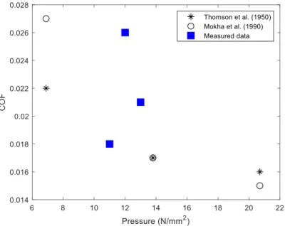
used to vary the normal pressure of the contact. The contact areas are approximated based on the optical and SEM images of the Teflon sheet after the experiments. As is shown, the measured COFs are ranging in between 0.018 and 0.026, comparable to the data reported by Thompson et al.[1] and Mokha et al. [2]. However, in our result, the trend of lower COFs with
higher normal pressures are not observed. This can be attributed to the difference in calculating the normal pressure of the contact: the contact area is assumed to be held constant with different normal forces in the literature whereas it is observed to change as the Teflon sheet at the contact deforms.
Nanoindentation: Instrumented nanoindentation experiments were performed using a
Triboindenter (Hysitron 950) at room temperature, calibrated on fused quartz. The FG-T+ tribo-layer was used after sliding test. During indentation process, the displacements versus the applied loads are recorded. Those records are then used to calculate the indentation hardness of the FG-T+ tribo-layer. Each point is separated by a distance of 2 µm.
1 2 3 4 5 6 7 8 9 10 11 12 13 14 15 16 17 18 19 20 21 22 23 24 25 26 27 28 29 30 31 32 33 34 35 36 37 38 39 40 41 42 43 44 45 46 47 48 49 50 51 52 53 54 55 56 57 58 59 60
Figure S1. (a) Synthesis of Triamnio-T. (b) FG-T from Hyper-3-Stage-1 graphite
intercalation compound (GIC). The Hyper-3-Stage-1 GIC represents the expanded gallery with intercalated tetrabutylammonium ion (TBA+) domains between the basal planes of
graphenes (TBAP = tetrabutylammonium perchlorate. (c) The size distribution of FG. (d) The optical micrograph of a graphene film on water surface. The graphene assembly on water surface is driven by Rayleigh–Bénard convection and Marangoni force.
1 2 3 4 5 6 7 8 9 10 11 12 13 14 15 16 17 18 19 20 21 22 23 24 25 26 27 28 29 30 31 32 33 34 35 36 37 38 39 40 41 42 43 44 45 46 47 48 49 50 51 52 53 54 55 56 57 58 59 60
Figure S2. (a) Attenuated total reflectance Fourier transform infrared spectroscopy
(ATR-FTIR) data of Triamino-T, FG, FG-T, and FG-T+. (b) Nuclear magnetic resonance spectroscopy (NMR) spectra of FG-T, and Triamino-T. FG-T (major): 1H NMR (400 MHz,
DMF-d7): δ 6.96-6.90 (m, 3H), 6.72-6.67 (m, 3H), 6.19-6.14 (m, 3H), 4.91 (s, 1H), 4.93 (s, 1H), 4.76 (br.s, 6H). 1 2 3 4 5 6 7 8 9 10 11 12 13 14 15 16 17 18 19 20 21 22 23 24 25 26 27 28 29 30 31 32 33 34 35 36 37 38 39 40 41 42 43 44 45 46 47 48 49 50 51 52 53 54 55 56 57 58 59 60
Figure S3. Top: Mechanical sliding-induced reconfiguration of a scratched FG-T+ film: The
reversible Meisenheimer complexes across the cracked film (intentionally scratched by a razor blade) was cured under mechanical shear force. Raman signature of FG-T+ from the recovered region. Bottom: Schematic illustration showing the formation of a tribo-layer against a DLC-coated SS ball.
1 2 3 4 5 6 7 8 9 10 11 12 13 14 15 16 17 18 19 20 21 22 23 24 25 26 27 28 29 30 31 32 33 34 35 36 37 38 39 40 41 42 43 44 45 46 47 48 49 50 51 52 53 54 55 56 57 58 59 60
Figure S4. (a) Experimental demonstration and coefficient of friction (COF) results of
graphene films. An image of the linear tribometer equipped with a DLC-coated SS ball. Tests were performed at room temperature (RT) under 3 N load (contact pressure: 0.3 ~ 0.4 GPa). Each sample was tested more than three times in order to ensure the reliability. The tapping-mode atomic force microscopy (AFM) surface scans and the Raman spectra of (b) a SS substrate, and (c) a DLC-coated SS ball.
1 2 3 4 5 6 7 8 9 10 11 12 13 14 15 16 17 18 19 20 21 22 23 24 25 26 27 28 29 30 31 32 33 34 35 36 37 38 39 40 41 42 43 44 45 46 47 48 49 50 51 52 53 54 55 56 57 58 59 60
Figure S5. Comparison of the COF between stainless steel balls and Teflon sheets measured
by the custom-built linear macro tribometer and the data from literature.[1,2] The ball diameter
of 9.5 mm is used to slide at the linear speed of 2.5 mm s−1 on the Teflon sheet of 0.9 mm
thickness. The contact pressures for the normal force of 1.5 N, 3 N and 6 N are estimated to be 12 N mm−2, 13 N mm−2, and 11 N mm−2, respectively. 1 2 3 4 5 6 7 8 9 10 11 12 13 14 15 16 17 18 19 20 21 22 23 24 25 26 27 28 29 30 31 32 33 34 35 36 37 38 39 40 41 42 43 44 45 46 47 48 49 50 51 52 53 54 55 56 57 58 59 60
Figure S6. (a) Scanning electron microscope (SEM) images with the corresponding energy
dispersive X-ray spectroscopy (EDS) carbon mapping of UEG, (b) FG, and (c) FG-T+ after sliding. 1 2 3 4 5 6 7 8 9 10 11 12 13 14 15 16 17 18 19 20 21 22 23 24 25 26 27 28 29 30 31 32 33 34 35 36 37 38 39 40 41 42 43 44 45 46 47 48 49 50 51 52 53 54 55 56 57 58 59 60
Figure S7. (a) A SEM image of the surface of diamond-like-carbon (DLC)-coated ball. The
sliding motions with the rough surface at contact edges highly cause the damages of coated materials. (b) The COF for DLC-coated ball sliding against UEG. As a result of the unstable tribo-layer formation on the SS substrate, the COF increases at the beginning of sliding and many large COF spikes appear. Similarly, graphene films on SiO2 surfaces display a
substantial amount of variance in the COF in sliding experiments against a DLC ball.[3] This
erratic nature of COF of pristine graphene coatings at macroscale levels will limit the operational lifespan of a mechanical components and/or require frequent reapplication of the lubricant. 1 2 3 4 5 6 7 8 9 10 11 12 13 14 15 16 17 18 19 20 21 22 23 24 25 26 27 28 29 30 31 32 33 34 35 36 37 38 39 40 41 42 43 44 45 46 47 48 49 50 51 52 53 54 55 56 57 58 59 60
Figure S8. The COF of UEG-nanodiamond in our system. The average of COF is 0.011. 1 2 3 4 5 6 7 8 9 10 11 12 13 14 15 16 17 18 19 20 21 22 23 24 25 26 27 28 29 30 31 32 33 34 35 36 37 38 39 40 41 42 43 44 45 46 47 48 49 50 51 52 53 54 55 56 57 58 59 60
Figure S9. Optical images and high resolution X-ray photoelectron spectroscopy (XPS) C 1s
spectra of (a) UEG (b) FG (c) FG-T, and (d) FG-T+ after sliding cycles. (e) (Top) The optical profile of the tribo-layer of FG-T+ on a SS substrate after sliding cycles. After sliding, the tribo-layer of FG-T+ was formed. (Bottom) Schematic illustration of reconfigurable networks of a FG-T+ matrix during sliding against a DLC-coated SS ball. The bottom of a FG-T+ matrix adheres to a SS substrate and the rest of the matrix provides reversible slip by Meisenheimer complexes. 1 2 3 4 5 6 7 8 9 10 11 12 13 14 15 16 17 18 19 20 21 22 23 24 25 26 27 28 29 30 31 32 33 34 35 36 37 38 39 40 41 42 43 44 45 46 47 48 49 50 51 52 53 54 55 56 57 58 59 60
Figure S10. (a) The optical profile of a DLC-coated SS ball before a friction test. The optical
profile and the COF of an intact DLC-coated SS ball against (b) a FG-T+-coated SS substrate and (c) an uncoated SS substrate in N2 environment. (b) Over 20000 cycles, the wear rate of
DLC-coated SS ball against FG-T+ on a SS substrate is 0.94 10−9 mm3 N−1 m−1. (c) The
wear rate of DLC-coated SS ball against an uncoated SS substrate is 9.94 10−9 mm3 N−1 m−1.
(d) An AFM surface scan of the uncoated SS substrate after sliding against a DLC-coated SS ball. We observed that the tribo-chemically generated particles due to the wear of a DLC/SS pair. The morphology is different from the FG-T+ in Figure 4d in main text. (e) Raman spectra of a SS substrate before and after sliding against DLC.
1 2 3 4 5 6 7 8 9 10 11 12 13 14 15 16 17 18 19 20 21 22 23 24 25 26 27 28 29 30 31 32 33 34 35 36 37 38 39 40 41 42 43 44 45 46 47 48 49 50 51 52 53 54 55 56 57 58 59 60
Figure S11. The COF of a DLC-coated ball against (a) a FG-T+-coated SS substrate, and (b)
a SS substrate in ambient environment. The COF of an uncoated SS ball against (c) a FG-T+-coated SS substrate and (f) a SS substrate in N2 environment. The COF of an uncoated SS ball
against (e) a FG-T+-coated SS substrate, and (f) a SS substrate in ambient environment.
1 2 3 4 5 6 7 8 9 10 11 12 13 14 15 16 17 18 19 20 21 22 23 24 25 26 27 28 29 30 31 32 33 34 35 36 37 38 39 40 41 42 43 44 45 46 47 48 49 50 51 52 53 54 55 56 57 58 59 60
Figure S12. XPS spectra of (a) uncoated SS, (b) Triamino-T, and (c) UEG-T before/after
sliding against DLC. During sliding, the Triamino-T and UEG-T also undergo tribo-chemically damage that causes unstable frictional sliding. (d) Raman spectra of the tribo-layer of uncoated SS, UEG, FG, UEG-T, UEG-T, FG-T, and FG-T+ after sliding against DLC. The tribo-layers of graphenes clearly show different chemical signatures after sliding against DLC, compared with the tribo-layer of uncoated SS. For example, the GFG-T+ band (1606
cm−1) of the tribo-layer of FG-T+ is distinguishable from the GDLC‐band (1578 cm−1) of DLC
debris. 1 2 3 4 5 6 7 8 9 10 11 12 13 14 15 16 17 18 19 20 21 22 23 24 25 26 27 28 29 30 31 32 33 34 35 36 37 38 39 40 41 42 43 44 45 46 47 48 49 50 51 52 53 54 55 56 57 58 59 60
Figure S13. AFM surface scans and TEM data of (a) UEG, and (b) FG tribo-layers. 1 2 3 4 5 6 7 8 9 10 11 12 13 14 15 16 17 18 19 20 21 22 23 24 25 26 27 28 29 30 31 32 33 34 35 36 37 38 39 40 41 42 43 44 45 46 47 48 49 50 51 52 53 54 55 56 57 58 59 60
Figure S14. AFM surface scan of the initial FG-T+ coating on a SS substrate before a friction
test. Reference
[1] J. B. Thompson, G. C. Turrell, B. W. Sandt,. SPE Journal 1995, 11, 13
[2] A. Mokha, M. Constantinou, A. Reinhorn, Journal of Structural Engineering 1990, 116, 438.
[3] D. Berman, S. A. Deshmukh, S. K. R. S. Sankaranarayanan, A. Erdemir, A. V. Sumant,
Science 2015, 348, 1118 1 2 3 4 5 6 7 8 9 10 11 12 13 14 15 16 17 18 19 20 21 22 23 24 25 26 27 28 29 30 31 32 33 34 35 36 37 38 39 40 41 42 43 44 45 46 47 48 49 50 51 52 53 54 55 56 57 58 59 60
Figure 1
Click here to access/download
Production Data
Figure 2
Click here to access/download
Production Data
Figure 3
Click here to access/download
Production Data
Figure 4