Publisher’s version / Version de l'éditeur:
Vous avez des questions? Nous pouvons vous aider. Pour communiquer directement avec un auteur, consultez la première page de la revue dans laquelle son article a été publié afin de trouver ses coordonnées. Si vous n’arrivez pas à les repérer, communiquez avec nous à PublicationsArchive-ArchivesPublications@nrc-cnrc.gc.ca.
Questions? Contact the NRC Publications Archive team at
PublicationsArchive-ArchivesPublications@nrc-cnrc.gc.ca. If you wish to email the authors directly, please see the first page of the publication for their contact information.
https://publications-cnrc.canada.ca/fra/droits
L’accès à ce site Web et l’utilisation de son contenu sont assujettis aux conditions présentées dans le site
LISEZ CES CONDITIONS ATTENTIVEMENT AVANT D’UTILISER CE SITE WEB.
Paper (National Research Council of Canada. Division of Building Research); no.
DBR-P-719, 1977-02
READ THESE TERMS AND CONDITIONS CAREFULLY BEFORE USING THIS WEBSITE. https://nrc-publications.canada.ca/eng/copyright
NRC Publications Archive Record / Notice des Archives des publications du CNRC :
https://nrc-publications.canada.ca/eng/view/object/?id=18b83cd4-6961-4309-9e99-f415016c6b48
https://publications-cnrc.canada.ca/fra/voir/objet/?id=18b83cd4-6961-4309-9e99-f415016c6b48
NRC Publications Archive
Archives des publications du CNRC
This publication could be one of several versions: author’s original, accepted manuscript or the publisher’s version. / La version de cette publication peut être l’une des suivantes : la version prépublication de l’auteur, la version acceptée du manuscrit ou la version de l’éditeur.
For the publisher’s version, please access the DOI link below./ Pour consulter la version de l’éditeur, utilisez le lien DOI ci-dessous.
https://doi.org/10.4224/40001674
Access and use of this website and the material on it are subject to the Terms and Conditions set forth at
Temperature distributions in fire-exposed building columns
A/2
Icl
National Research
Conseil national
0.
-7
1
$
Council Canada
e.
2
de recherches Canada
TEMPERATURE DISTRIBUTIONS IN FIRE-EXPOSED
BUILDING COLUMNS
by T.T. Lie
Reprinted from
Journal of Heat Transfer
Vol. 99, Series C, No. 1, February 1977
p.
113
-
119
DBR Paper No. 719
Division of Building Research
SO
MMAIRE
L t a u t e u r dCcrit un mode de calcul, fond6 s u r une mCthode d e s ClCments finis, de l a courbe de tempkrature des poteaux d t a c i e r protCgCs exposCs au feu, de coupe rectangulaire et dont l'isolant comporte une gCnCration ou une absorption de chaleur. Une comparaison avec des rCsultats d l e s s a i s et avec d e s rCsultats fournis p a r une solution analytique des Cquations de t r a n s m i s - sion de l a chaleur indique que l a mCthode offre une precision adequate aux fins de l a sc;ience du feu. La mgthode s e pr6te Cgalement au calcul de l a temperature d e s ClCments de con- struction monolithiques comme l e s poteaux, l e s poutres e t l e s m u r s de bCton pleins. Elle peut a u s s i s e r v i r
'a
calculer l a tem- pCrature de tout systBme dans lequel un conducteur parfait ou un fluide bien agitC e s t enfermC dans un revGtement, comme c t e s t l e c a s des poutres ou des poteaux creux d l a c i e r r e m p l i sd'eau, et expose
'a
une s o u r c e de chaleur rayonnante de tem-Reprinted from JOURNAL O F HEAT TRANSFER, Vol. 99, No. I, February 1977
T. T. Lie
Research Ofllcer, Flre Research Saclion, Divislon of Bulldlng Rmarch, National Research Councll of Canada.
.
Ottawa, Canada.Introduction
Temperature Distributions in Fire-
Exposed Building Columns
A procedure based on a finite difference method is described for calculating the tempem- ture history of fire-exposed protected steel columns with rectangular cross section a n d heat generation or absorption in the insulation. Comparison with results of tests a n d those obtained from a n analytical solution of the heat transfer equations indicates that the accuracy of the method is adequate for fire engineering purposes. The method is also suitable for the calculation of temperatures in monolithic building components such a s solid concrete columns, beams, a n d walls. I t can also be used for the calculation of temper- atures of a n y system in which a perfect conductor or well stirred fluid is enclosed in a n en- casement, for example, water-filled hollow steel columns or beams, a n d exposed to a radi- ative heat source of varying temperature.
I t is known that exposure to fire reduces the strength of load- hearing building components such as columns, beams, and walls. One method of preventing excessive loss of strength and consequent col- lapse of a building is to restrict the temperature rise in these compo- nents by providing protection. One of the problems in selecting an appropriate protection is the evaluation of its effect on the fire per- formance of a component. In the past this could be determined only by experiment. Recent developments, however, have made it possible to solve many fire performance problems by calculation, which is far less expensive and time consuming.
In order to calculate the fire performance of a building component it is necessary to know the temperature history of the component during exposure to fire. In this paper a numerical method is described for the calculation of the temperature field in fire-exposed columns. 'I'he calculation procedure is based on an improved version of a finite difference method, which offers the advantage of a network of points with which the corners of rectangular configurations can be reached without difficulty [I).' It wasapplied in a study [2] describing the heat flow in fire-exposed square steel columns protected by an insulating material. In the present paper, this study is extended to the calcula- tion of the temperature history of columns with rectangular cross sections (Fig. 1). In addition, the possibility of taking into account heat generation or heat absorption by the protecting material has been
'
Nurn1)t.r~ in brackets designate References at end of' paper.170nlril)uted hy the Heal 'I'ransler Ilivision I'or publication in the .JOUHNAL.
OF HEAT TRANSFER. Manuscript received by the Heat Transfer Ilivision March 29. 1976.
included. Furthermore, comparisons made in a previous paper [2] between calculated and experimental results are supplemented in this paper by comparisons between results obtained from the numerical method and those from a n analytical solution of the heat transfer equations.
Calculation Method
With the technique described earlier [I, 21, the cross section of the insulating protection is divided into several elementary regions as
Fig. 1 Cross section of a typical protected steel column
Journal of Heat Transfer
FEBRUARY 1977
/
113
Fig. 2 The arrangement of the elementary regions ol a one-quarter section of column protection
shown in Fig. 2. They are square inside the insulation and triangular a t its boundaries. The temperature a t the center of each element is taken as representative of that of the entire element. T h e represen- tative point for each triangular boundary element is located on the hypotenuse.
Because the thermal conductivity of steel is normally a t least 20 times higher than that of the protection, steel will be considered as a perfect conductor. This implies that the temperature of the steel core will be assumed to be uniform over its entire volume. Conse- quently, the two-dimensional network need not be extended over the cross-sectional area of the steel core. Instead the subdivision of the steel core can be done in a more convenient way as will be described later. Furthermore, it will be assumed that the capacity of the air enclosed by the protection is negligible in comparison with that of the steel.
For reasons of symmetry, only one-quarter of the section need be considered when calculating the temperature distribution in a cross section. As shown in Fig. 2 in an x-y coordinate system the repre-
sentative point of the protection P,,,,,, for the region R,
,,
has the coordinates x = (rn-
1 ) A ( / f i and y = ( n-
1 ) A(/V"2. The points rn = 1 and n = 1 coincide with the origin x = 0 and y = 0 . rn increases in the x direction and attains a value rn = M a t the boundary A-
H. where as n increases in t h e y direction and has a value n = N a t the Iwundary H-
('. As can be seen in the figure, only those points of I he x-y plane are defined for which (rn+
n ) is a n odd number.T o calculate the temperature history of the insulation and steel, a heat equation is written for each elementary region for the times j J t where j = 0 , 1 , 2 .
. .
and At is an appropriate time increment. With the aid of these equations, the temperature of each region can be successively evaluated for any time t = 6+
1 ) At if the temperature a t the time t = j A t is known.I t should be mentioned that the applicability of the method to be described is not limited to protected steel columns. I t can be applied to any assembly consisting of a central core of a well stirred material or a material with relatively high thermal conductivity, surrounded by a rectangular envelope of much lower conductivity, which is ex- posed to heating on all four sides. By removing the core and extending the insulation to the center of the section, it can also be used for the calculation of the temperature history of monolithic columns or beams.
Moisture movement is not taken into account in the model. The effect of moisture on the temperature rise of steel is in general small, and in most cases negligible. Under normal conditions, usually as- sumed to be an environment of about 5 0 percent relative humidity and 20°C temperature, most inorganic building materials d o not hold mpre than 1 percent moisture by volume. For such materials the effect of moisture on the time to reach the critical steel temperature is a few percent and not significant. Concretes, however, may hold 3 4 percent of moisture. Experiments and calculations, using a model in which it is assumed that the moisture moves to the inner surface of the in- sulation and evaporates a t this surface, indicate that the predicted failure times will be on the safe side by about 10 to 15 percent 12). I t is possible to make a correction for the effect of moistwe using a semi-empirical method. For application in practice, however, a safety margin of 10 to 15 percent is acceptable. I t is likely that for concretes the main deviations from calculated results will in practice be caused by the variability of the thermal properties of the concrete, since this is normally a mixture of cement, sand, and gravel of various shape, size, and composition. Spalling of the concrete may also significantly affect the fire performance of a column.
Equations for the Outer Boundary of Insulation
In a fire, heat is transferred from the fire to an exposed object by convection and radiation. According to existing information the heat
M = number of mesh points along the x - pr
a = coefficient axis = density of insulation
A = area of the inner surface of the insula- n = = 1 , 2 , 3 , .
. .
.
n = Stefan-Boltzmann constanttion N = number of mesh points along the y -
h = coefficient axis Subscripts
c = specific heat; without subscript: specific heat of insulation d = coefficicn'
D
= thickness of insulation pc A h = - r , W ;= = O , l , 2, . . . .
k = thermal conductivity of insulation K = number of mesh points in and on the
insulation along the x-axis
P = point
Q = rate of heat generation or absorption R = elementary region
t = time
T
= temperature W = mass of steel core x = coordinate y = coordinatet r = fraction
f i = roots of fitg@D = h J = increment
P = distance in insulation = mesh width
L = number of mesh in and on the in- c = emissivity sulation along the y-axis 7 = emissivity factor
114
/
FEBRUARY 1977
a = average
f = of the fire 1
i = of the insulation I
k = = l , 2 , 3
, . . .
1rn, M = a t a mesh point in the n t h or Mth !
column, respectively !
n. N = a t a mesh point in the n t h or Nth row. respectively
0 = initial
r = pertaining to radiat,ion
s = of the steel core
I
Superscript
j = a t t = j J t
~ral~sferred in a typical case by convection to an object is less than 10 1)c~rcent of the radiat.ive heat 131. I t is known that above a certain level ol'lhe c:oen'icient of heat transfer, which is easily obtained in fires and furnaces, the temperature of the surface of the exposed object will be very close 10 lhe temperature ofthe environment 15,121. In this region c.h;ingt:s o f the order of 10 percent will have little effect on the surface I.ernperature and thus on the temperature in the exposed object. 'I'herefore, to simplify the heat transfer model, the convective heat I ransfer will be neglected in this study.
Furthermore, it will be assumed that the radiative heat transfer to the exposed object is approximately that of a black body. As explained subsequently, this assumption will cause only a small error.
In an actual fire, heat is received from luminous flames, which have a high emissivity. If the thickness of the flames is sufficient, the emissivity may reach values of about 0.9 or higher, and thus ap- proaches that of a black body. For the same reason as in the case of convection, an error of the order of 10 percent in the radiative heat transfer will have little effect on the surface temperatures of the ex- posed object if the heat transfer is high. T h e high heat transfer from lires is simulated in furnaces by making them large, so that the flames have sufficient thickness, and by selecting furnace wall materials that produce wall temperatures close to the flame temperature. In the present study a column is considered that is exposed to fire on four sides. It will be assumed that the fire temeerature follows a standard temperature-time relation according to that specified in ASTM El 19-73 141, although the calculation procedure is valid for any other temperature-time relation. Several analytical expressions that ap- proximately describe this curve exist 15, 61. Here the following ex- pression will be used:
T, = 7'0
+
1200 - 550 exp (-0.6t)+200 exp (-3.0t)
-
850 exp (-12.01) (1) where 7; and TI) are, respectively, the fire and ambient temperature in degrees centigrade and t is the time after the start of the fire in hours. This form, consisting of exponential functions, has been chosen because ofthe advantage that when used as a boundary condition the heat transfer equations are analytically solvable.The heal transmitted from the fire to an elementary surface region HM.,, along the boundary A-R (see Fig. 2) during the period ;At
<
t d+
1 ) At for a unit height of the column can be written asFrom the region R M , ~ heat is transferred by conduction to the two neighboring regions, R(M-I),(,,-I) and R(M-]),(,,+ 1). This heat can be given as
( ~ I M - I I , I , , - I ,
+
k ~ t r ~)
(TM.n1
-
TIM-,),in-14)2
During exposure heat may he generated in the protecting material, I~ecause ol'dec:omposition of the material. I1 is also possiO1e that heat is ahsorhed because ot' dehydration or transformation processes in the material. If Q is the rate of heat generation (+) or ahsorption (-) per unit volume, then the heat gain or loss in an elementary region KM,,, because ofthis heat generation or absorption is Li)r a time peritd A1
lP2(A()2 QAt ('4)
The sensible heat absorhed by the element in this period is 1/2(A02 ( p c ) ~ , n I ( T M . ~ ~ " - TM.,, ') (5) Ry adding all heat gains and losses given by equations (2)-(5), the following heat balance for an elementary region RM,,, is obtained:
'I'he temperature TM,,J+l a t the time
+
1)At for an elementary region RM,,, can be solved for from the equation (6). For an elementary region R,,,,N along the boundary R-
C (Fig. 2) the temperature T n , , ~ J + can be derived in a similar manner.In equation (6) the quantities p , c, k, c , , and
(2
are assumed lo I)eknown. If the temperatures in all elementary regions a t the time t = jAt are known, the temperatures in these regions a t the time t = ( j
+
1 ) At can be calculated from these equations. By using the newly calculated temperatures of the various regions as initial temperature and repeating the calculation process, the temperatures a t t,he times (j+
2) At, (j+
3) At, etc., can be derived for each elementary re- gion.Equations for the Inside of Insulation
In the same way as for elementary regions a t the outer boundary, the temperatures in the insulation can be calculated by writing heat balance equations for the inside elementary regions. For a region K,,,,,, represented by point P,,,,,,, the heat balance equation for a unit height of the column and a time period At is
The temperature T,,,.,,J+I of an inside elementary region R,,,,, a t the time
+
1) At can be solved for from equation (7).Equations for the Inner Boundary of Insulation and
for the Steel Core
T o describe the heat transfer along the inner boundary ot' the in- sulation a model presented in a previous paper [2] will be used. As shown in Fig. 1, a certain fraction a of the inner surface of the insu- lation of a protected steel column is usually in direct contact with the steel core, and a fraction (1 - n ) is separated from the steel core by an air gap. T h e mechanism of heat transfer along the areas of contact is conduction. Heat is transferred through the air gap by radiation and convection. Because the radiative heat transfer is predominant a t temperatures normally found in protected steel columns during fire exposure, the convective heat transfer is not taken into account. It can he shown by estimating the maximum steel temperature rise that can be caused by free convection that, for columns normally met with in practice, the heat transferred to the steel by convection is small in comparison with that by conduction and radiation. For example, for a steel column that has been tested (Fig. 6), it can be derived that the temperature rise of the steel in one hour because of convective heating is less than 2OC. This is a small fraction of the temperature rise of about 350°C in one hour measured during the test. In the derivation it has been assumed that the heat transfer by convection resembles that of a vertical plate in air. Because in reality the top and bottom of the column are closed, thi; model overestimates the con- vective heat transfer. The air temperature has been assumed to be 10°C higher than the steel temperature a t any time, which is ap- proximately the maximum temperature difference observed during tests in the space enclosed by the insulation. The area of the steel exposed to heating by convection is 0.5 m' and the mass of the steel 73 kglm length.
M A S S
OF
MASSOF
STEEL ELEMENT STEEL ELEMENT
C = C O N D U C T I V E H E A T F L U X R = R A D I A T I V E H E A T F L U X
Fig. 3 Model of rnechanlsm d heat transfer for a triangular elementary region of the inner surface of Insulation
The model to describe the mechanism of heat transfer a t t r i a n d a r
.,
elementary regions of the inner surface of the insulation is shown in Fig. 8. In this model the total mass of the steel core is divided into a number of elementary pieces equal to the number of elementary re- gions along the inner surface of the insulation, i.e., into 2(N-
L
+
M-
K-
2) pieces. I t is assumed that a fraction n of each elementary mass is in direct contact with the adjacent elementary insulation surface, and thus receives heat from the insulation by conduction, while a fraction (1-
n ) of its mass is a t some distance from the ele- mentary surface and receives heat by radiation. By varying a from0 to 1 all possible practical conditions, including pure radiative and pure conductive heat transfer to the steel core, can be simulated. If the steel is everywhere in contact with the insulation, for example, in the case of tubular steel columns, or = 1. If there is no contact, as in the case of a wall built around the steel without touching it, a = 0.
In the case of the column shown in Fig. 1, n is approximately 0.5. In practice the shape and size of the columns are known and a can be estimated, but considering the worst case of a = 1 is probably suffi- cient.
Along the boundary D
-
E (see Fig. 2), the radiative heat trans- ferred to the steel core from the elementary region R(M-K+ ,),,, througha fraction ( 1 - cr) of the inner surface of the insulation bounding this region is during the period ;At
<
t<
(j+
1 ) AtI n the same period heat is transferred by conduction from the neighboring regions to each triangular elementary region R , M - K + I ).,,
a t the inner surface of the insulation, and to each fraction of the ele- mentary steel masses that are in contact with the inner insulation surface. Since, by assumption, steel is regarded as a perfect conductor, the temperatures of those fractions of elementary steel masses that are in direct contact with the insulation surface are identical to those of the adjncrnt. elementary regions of insulation. Consequently, their presence can be taken into account by adding their heat capacities to those of the adjacent elementary insulation regions.
By adding all heat gains and losses, the following heat balance equation can be written for a period ;At
<
t<
(i+
1 ) At for each tri- angular elementary region R ( M - K + ~ ) . , , and each fraction of steel at- tached to it:116
/
FEBRUARY 1977
where ( C . , ) ( M - ~ + I ),,,I is the specific heat of steel a t a temperature of'
T I M - K + I I , ~ J .
T h e temperature T ( , + - K + ~ , , , , J + ' of an elementary region
R I M - K + l ) , n with attached steel fraction, along the boundary I ) - ti
a t the time
+
l ) A t , can be found by solving equation (9) for this temperature. For the boundary E-
F (Fig. 2) the temperatureTm.(N-I,+j)'+l of an elementary region RM.(N-I,+ 1 1 with attached steel
fraction can be derived in a similar manner.
One of the parameters still unknown in equation 9 is the steel temperature T . v , ~ of that part of the steel that receives heat by ra- diation. Although the model assumes that the steel temperature is uniform, evaluation of T,,J is necessary, as an intermediate step in the procedure of calculation of the uniform steel temperature. This steel temperature is obtained later by adding all enthalpies of'the steel elements, part of which are heated by radiation and part by conduc- tion, and dividing the sum by the heat capacity of the steel.
T,,J can be derived in a similar way to the temperatures ol'the el-
ementary regions in the insulation by writing a heat balance for the steel. From such a heat balance it follows that the temperature T,,.lt
'
a t the time (j
+
1) At is given byT,,J+I = Tsr]
+
4 4[
Nc'
1 1+
273)c,,' W ,,=:i,5.
M - K
+
X
( T m . ( ~ - ~ . + l r '+
27314m =:3..5.
. .
Although the temperature field in the protection may be of' interest in other cases, e.g., if the protection is made of concrete and contrib- utes to carrying the loading, normally the temperature of the steel core is of primary importance. Because this temperature often determines the strength of the steel, knowledge of it is essential for predicting the time of collapse of building components.
The steel core temperature can be derived by equating the enthalpy of the steel core to that of the sum of the enthalpies of all steel pieces constituting the steel core. This results in the following equation:
where
T,J+I = the steel core temperature a t the time (j
+
1) Atc, = the specific heat of steel
According to available data 17, 81, the specific heat of' steel may be given as a function of its temperature T by the expression
c, = 440
+
0.478T (12)where c, is in J/kg°C and T in OC.
Substitution of c., in equation (1 1 ) and integrating gives for the steel core temperature
Auxiliary Equations
T o calculate the temperatures of the elementary regions along the lines of symmetry A
-
D and F-
C, it is necessary to know the tem- peratures of the regions p,,~ and PI,,. These temperatures are ob- tained by equating the temperatures of symmetrical points. T h u s along line A - D :and along line
F
- C.With the aid of equations (6). (7), (9), (lo), and (13)-(15), it is now ~)ossit)le to calculate the temperature distribution in the insulation,
on ils houndaries, and the temperature of the steel core for any (j
+
1 ) At time level, il'the lemperatures a t the ;At level are known. Ini- tially, only the temperatures a t the t = 0 level, which are usually equal to room temperature, are known. Starting from these temperatures, the temperature history of the protection and the steel core can be determined up to any specified time or temperature level with the aid of the aforementioned equations.
It is known that the solutions are not stable for all values of the mesh width A( and time increment At. In order to insure that any error existing in the solution a t some time level will not be amplified in the subsequent calculations, a stability criterion has to be satisfied which for a selected value of A( limits the maximum value of At [9].
For fire-exposed columns and beams the criterion of stability is usually most restrictive along the boundary A
-
R between fire and insulation.Analytical Solution
In previous studies [2,10], calculated results were compared with
600 5 0 0 - 400
-
300-
-
2 PO-
EXPERIMENTAL 100---
CALCULATED-
0 0 20 40 6 0 8 0 100 120 140 160 rx 32
300-
- CL u-
.x EXPERIMENTAL---
CALCULATED-
C-
I I I I TIME. M I N U T E SFig. 5 Steel temperature as a function of tlme (size steel core: 20 X 20 cm; insulation of heavy clay brick)
experimental results for a number of steel sizes and protecting ma- terials. The comparisons showed that for these cases the maximum deviation between calculated and experimental temperatures was about 15 percent, which may be regarded as reasonably accurate in the field of fire engineering. A few of the comparisons are shown in Figs. 4 4 . In Figs. 4 and 5 measured and calculated steel temperatures are compared for protected steel columns that were exposed to heating a t temperatures according to the standard temperature-time relation given hy equation (1). In Fig. 6 the comparison is for a column that was exposed to heating according to a temperature-time curve that closely resembles an actual fire temperature curve. To obtain more information on the accuracy of the numerical method, the results ohtained by the method described in this paper will also be compared with those obtained from analytical solutions of the equations that determine the steel temperature. For this purpose a protected steel column will he considered of which the steel is everywhere in contact with the insulation (a = 1). If certain assumptions are satisfied, it is possible to give an analytical solution of these equations. T h e as- sumptions are
( a ) The heat that passes the insulating casing is immediately and
uniformly distributed over the steel;
( b ) The thermal capacity of the air cavity (if any) enclosed hy the casing is negligible in relation to that of the steel;
(c) The insulation is so thin that the difference in insulation
thickness a t the comers can be neglected and it is permissible to
1000 I I /.-.---I I I 1 I I q00-
,+/-
.
F U R N A C f - \ - r F M P f R A T U R E /-'
.
- 700-/'
EXPERIMENTAL C A L L U L A T E D TIME, MINUTES T I M E . M I N U T E SFig. 4 Steel temperature as a function of time (size steel core: 15 X 15 cm; Fig. 6 Steel and furnace temperature as a function of time (size steel core: insulation of insulating Hre brick) 25 X 25 cm; Insulation of vermiculie board)
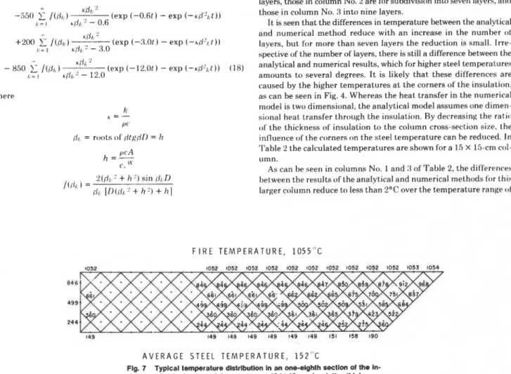
I F I R E TEMPERATURE, 1 0 5 5 ° C 1052 1052 1052 1052 1052 1052 1052 1052 1052 1052 1052 I053 1054 846 499 244 149 149 149 149 149 149 149 151 158 190 A V E R A G E STEEL TEMPERATURE, 1 5 2 ° C
Fig. 7 Typical temperature distribution in an one-eighth section of the in- sulation of a steel column (size steel core: 10 X 10 cm: insulation thickness: 1 cm: exposure time: 2 hours)
118
/
FEBRUARY 1977
Transactions of
the ASME
(,o~~siclor 41 I I C - Z I ~ i'low t11ro11gh t hv IIISIII;II ion O V ( ~ ~ Z I I I ;artB;i ( V I I I ; ~ ~ to t lq'(>r ( ~ I I : I ~ ~ ~ ) I I ( iH) 7'- ;111(l Z I ~ V i l l ( l ( ~ ~ r c c ~ s ( ~ e n t i ~ r ; ~ ( l ( ~ , / I I I I I O I I ~ S , ;111(l
;irc;l 01 I I I ( $ IIII(~~I;I(.(* l ) ( ~ t w ( ~ t : ~ ~ I hv IIISIII;I~ I I I ~ I I I ; I ~ ( ~ I - I L I ~ ~ I I I ~ tlic- ( ~ o I I I ( ~ I I I s ; A I I I sqlltlrtA ~ ~ ~ ( ~ t t ~ r s per hour.
end
( d ) 'I'h(* matrrit~l constants are invariable or can he replacecl by
~~~~~~i~~~ of ~
~
of ~
~
~
~
and Analytical
l
~
t
~
~
~
i
~
~
l
a c-onstant averagcs value.
Method
The heat transfer tbclr~ation and houndary and initial conditions that F~~ comparison a column mo(iel and were. determine the temperature in the insulation and steel are as Sol- chosen that as as those assumc,tl i n lows: analytical method. T o approach one-dimensional heat transl'er
The temperature of' the insulation 7' sat,isfies the differential the insulation i t be thin in with the inn(,,. equation for thermal conduction: perimeter of the cross section o f t h e insulation. In this case an insrl-
dT d27' lation thickness of 1 cm and two steel core sizes of' 10 X 10 cm and I5 /I(.-= k -
at
a t '
( I 6 ) X 15 cm cross section were selected. To olltain temperat,ures o n the fire-exposed surface that closely follow the fire temperature course, At the exposed surface of the insulation. the temperature is as- it isessential that the thermal , ) f t h e inSulalion lje suc.h that sumed to follow the fire temperature course given hy equation (1 ). the prOduc.,k,,,,c, he low 1121, A coml,ination that was found toAt the interhce between insulation and steel, the heat flow per unit duce surface temperatures that were reasonably close to the fire time to the steel is equal to the increase in ent,halpy ofthe steel. Hence, temperature (see ~ i7 ) and did ~ , not give rise to extremely long cal- for
P
= l) culation times was k; = 50 J l m h OC; p,c, = 3 X 10" J/mil OC.dT d T T o make conditions in the numerical method as close as pr)ssil)lt. -/:A-=c, W-
if
e
i)l ( I 7 ' to those in the analytical method, it was assumed that the emissivity of both the fire and insulation was one, and that the mechanism 01' lnitiall!., the te~nperature of the column is equal to the room tem- heat from the irlsu~atiOn to the steel was conduc,ion. par perature, so that 7' = I'or t = 0. the mass of the steel a value of20 kg/m column length was chosen andThe method of solving the foregoing equat.ions is given in reference lor t,he heat a value equal to that given by equation ( 17) for 11 I]. In principle, this method uses the solution of equations (16) and a temperature of 2 0 0 ~ .
(17) for a constant fire temperature 1121 as starting point. With the calculated results given i n the ~ ~1 and 2, h I,, lrral,lr I tlllb ~ ~ aid of'1)uhamel's theorem, the solution for varying fire temperature steel temperatures a t various times ere shown for a 10 x stt,rl is derived. For a temperature rise a t the exposed surhce that follows column insulated by a 1 .cm thick protect,ion, (:()lumn N(), 1 ol' I he the t,emperature-time relation given k)y equation ( I ) , the solution for Table gives the temperatures calculated hy the analytical rnethod, the steel temperature T , is as follows: and columns 2,3, and 4 give the average steel temperatures calculated by the numerical method for various mesh widths. The temperatures
T , - T , ) = 1200
-
1200 exp (-&I. t ) in column No. 2 are for a 1-cm thick insulation subdivided into five I:= Ilayers, those in column No. 2 are for subdivision into seven layers, and
.@/<
'
-550
2
f(81:) (exp (-O.6t)-
exp (-~@')l:t)) those in column No. 3 into nine layers.I hp'lg2-0.6 It is seen that the differences in temperature between the analytical
.@I:
'
and numerical method reduce with a n increase in the number of+200
f
/(PI:) (exp (-8.0t) - exp (-hij2/,t)) layers, but for more than seven layers the reduction is small. Irre-/ ; = I ~ / j , , '
-
3.0spective of the number of layers, there is still a difference between the - 850
2:
/(fik)
riir'
(exp (- 12.0L)-
exp (-Klr21it ) ) (18) analytical and numerical results, which for higher steel temperaturesk = I h[f/<'! - 12.0 amounts to several degrees. I t is likely that these differences are
caused by the higher temperatures a t the corners of the insulation. where as can be seen in Fig. 4. Whereas the heat transfer in the numerical k model is two dimensional, the analytical model assumes one dimen- sional heat transfer through the insulation. By decreasing the ratio /I('
of the thickness of insulation to the column cross-section size. the
6,.
= roots of (.ltg@lI = h influence o f t h e comers on the steel temperature can he reduced. In ,,cA Table 2 the calculat.ed temperatures are shown for a 15 X 15-cm col-h = - umn.
C.
As can be seen in columns No. 1 and 3 of Table 2, the differences 2((ja.'
+
h') sin /jl..L) between the results of the analytical and numerical met,hods for this f (ijl. ) =TaMe 1 Steel temperature (Co) 01 10- X 10-cm column
-
- -ANAI.Y'TICAI. N U M I R I C A L MI:1YIOIl
MI~'l11011 US I 7 l.AYlllS
I
9 LAYERSI
41 i l l (,(I l)o I ?cr I 541 181) 1111 2411 ?:(I TO11
Table 2 Steel temperature (Co) of 15- X 15-cm column
NIJMI:I<I(:AI. f.,l l:lOl)
.. - -- - ... - -
20 to approximately 500°C. In terms of the time to reach a specific steel temperature the differences are less than 1 min. In the field of fire resistance of building components such an error is negligible. Even if the faster method is used by dividing the insulation into five layers instead of seven, the errors are still small, as shown in column No. 2 of Table 2.
Conclusion
In the past the fire performance of building components could be determined only by experiment. Recent developments, in particular development of numerical techniques and better knowledge of ma- terial properties a t elevated temperatures, have made it possible to solve many fire performance problems by calculation. Calculation has the advantage that it is far less expensive and time consuming than performance tests.
In this study a procedure based on a finite difference method is described for calculating the temperature history of fire-exposed protected steel columns with rectangular cross section and heat generation or absorption in the insulation. Comparison with results of tests and those obtained from an analytical solution of the heat transfer equations indicates that the accuracy is adequate for fire engineering purposes.
The method is also suitable for the calculation of temperatures in monolithic building components such as solid concrete columns, beams, and walls. I t can also be used for the calculation of tempera- tures of any system in which a perfect conductor or well stirred fluid is enclosed in an encasement, for example, water-filled hollow steel columns or beams, and exposed to a radiative heat source of varying temperature.
This paper is a contribution from the Division of Building Research,
L O . 0 20 , 1' 2 2 . 8 25.1. 5 6 . 7 hZ.? Il(1.7 1 2 ? . 1 1 8 6 . 3 191.8 258. h 264.1 330. 2 3 3 6 . 3 39s F 4 0 6 . : 466.2 4 7 2 . 8 497.9 504 . A
National Research Council of Canada, and is published with the ap- proval of the Director of the Division.
References
I Harmathy, T . Z.. "Thermal Performance of Concrete Masonry Walls in Fire," American Society for Testing and Materials, Special Technical I'uh- lication No. 464. 1970. pp. 209-243.
2 Lie, 'l'. T., and Harmathy. T. Z.. "A Numerical Procedure l o Calculate the Temperalure of Protected Steel Columns Exposed to Fire," Fire Study No. 28, Division of'Ruilding Kesearch, National Research Council ~I'Canada. 1972, NRCC 125:15.
:j 'I'rinks, W., and Mawhinney, M. W., Indus/rial 1.lrrnacc.s. Carnegie Insl.
Technology. Wiley. New York, 1961.
4 "Standard Methods of Fire Tests of Building Constructions and Ma- terials," American Society for Testing and Materials. Designation E l 19-73, Part 18.1974, pp. 610-628.
5 1,ie. T . 'l'., Firr a n d Buildings. Applied Science l'uhlishers 1.t.d.. I.ondon, 1972.
6 Williams-Leir, G., "Analytic Equivalents oTStandard Fire Temperature ('urves," Firr, Trchnology. Vol. 9, No. 2, 1973, pp. 132-l:l6.
7 Liley. 1'. E.. Touloukian, Y. S., and Gamhill, W. R.. Physical ond ('hrmical Ilala. Chemical Bnginrt,rs Handbook, .I. H. I'erry, Sec. :l., McGraw-Hill, New York, 196:1.
8 British Iron Steel Res. Assoc., I'hysical Constants of Somcj ('omn~crciol S I ~ ~ r l s a t B l r u a l ~ d Trmpc-rnlures, Rutterworths Sci. Puhl., 1,ondon. 1953.
9 Dusinberre, (:. M., Hral Tranafc,r C a l c u l a t ~ n ~ ~ s by I . ' I ~ ~ / I . I)iffrrc~ncc~s. International Textbook Company, Scranton, I'a., 1961.
10 Konicek, L., and Lie, T. T.. "Fire Tests on Protected Steel Columns under Different Fire Severities," Fire Study No. 94, Division o f ' Building He- search, National Research Council of Canada, 1974, NHCC 14170.
11 Lie, 'l'. T., "Temperature of Protected Steel in Fire. Hehaviour 01' Structural Steel in Fire," Symposium No. 2, Ministry of Technology and Fire Offices' Committee Joint Fire Research Organization, H.M.S.O., Imndon. 1968. pp. 100-110.
12 Carslaw. H. S., and Jaeger, J . (:., C o n d u c ~ l r ~ r ~ ~ of H(YI/ In Solids. 0xl;lrd University Press, London. 1959.