Prof. S. J. Mason Prof. R. D. Thornton B. J. Leon
Prof. H. J. Zimmermann J. T. Andreika T. G. Stockham, Jr. Prof. J. Granlund D. G. Kocher E. H. Sussenguth Prof. C. L. Searle D. B. Leeson S. Weinreb
A. PARAMETRIC AMPLIFICATION
In the last two years there has been considerable interest in a new type of high-frequency amplifier called by such names as parametric amplifier, varactor, variable-reactance amplifier, and so forth. The active elements in this class of amplifiers are variable-reactance parameters; that is, inductances or capacitances whose values are made to vary periodically. The power that amplifies the desired signal comes from the source that varies the parameter. A suitable model for ascertaining the small-signal performance of a parametric amplifying device is a linear electrical network with one, or at most a few, linear, dependent reactances imbedded in a lumped, time-invariant circuit.
The primary objective of this investigation was the development of a general method for analyzing single-stage, linear, parametric amplifiers with steady-state signal inputs.
As a secondary objective, we wanted an analysis technique that is suitable for
CR
O(t) n Ck t circuits with more than one time-variant
OR O C(t)= Ck jkupt
w) ¥= , element and for transient as well as
steady-state inputs. Finally, we wanted Fig. XXI-1. Single-stage, linear, para- the analysis to yield currents and voltages
metric amplifier. that are functions of the complex fre-quency. Then when a parametric fier is used in conjunction with a linear, time-invariant system, the results of the ampli-fier analysis can be used directly in the frequency-domain analysis of the rest of the system without the need for laborious transforms.
The parametric amplification study has been completed with all objectives accom-plished. The research is to be presented to the Department of Electrical Engineering, M. I. T., as an Sc.D. thesis. In this study we used the network of Fig. XXI-1 as the basic model. This model consists of a periodic time-variant capacitance and an RLC time-invariant network, whose impulse response is y(t), driven by a current source. The extension to cascade networks with several variable elements is straightforward. For the one-node circuit of Fig. XXI-1, Kirchhoff's current law gives the
This research was supported in part by Purchase Order DDL-BZZ2 with Lincoln Laboratory, which is supported by the Department of the Army, the Department of the Navy, and the Department of the Air Force under Contract AF19(604)-5200 with M. I. T.
frequency-domain equation n
I(w) = Y(w) V(w) + jw CkV(w - kwo) (1)
-n
Equation 1 is a linear difference equation with rational coefficients. The solution, V(w), is a complex-valued function defined for all complex values of w. For the special case with n = 1 and I(w) = Ia 6(w - a ), the Fourier transform of an exponential of complex
amplitude Ia at frequency wa was investigated in detail. The generalization to
higher-order difference equations is straightforward. Methods for handling transient, as well as steady-state, voltages were also studied and found to be straightforward, but messy.
For the special case considered, Eq. 1 becomes
I (w - a) = (Y(w) + juC ) V(w) + jw CIV( - o) + Cl V(w (2)
By using the calculus of finite differences (1), we are led to a solution of the form
00
V() = k= Vk 6(w -a - kwo) (3)
k=-0(
where the Vk are complex constants. The functional form of Eq. 3 is already well
known; however, the method developed in the present study evaluates each of the Vk exactly, independent of the knowledge of any other Vk . This method is therefore much
more general than the method of Bolle (2), which is commonly used in parametric anal-ysis.
By studying the procedure for the exact determination of the Vk we have been able to prove several facts:
(a) The high-frequency voltages, which are not considered in most analyses, go to zero in such a way that the total power carried by them is finite as long as the variable capacitance, C(t), is positive for all time.
(b) The gain of a parametric amplifier is independent of the magnitude and phase of
the input signal except in the degenerate case wa = (n/2) oo.
(c) The presence of a resonant circuit at the idler frequency (o - a I) is a suffi-cient condition for gain. If the idler is suffisuffi-ciently sharp, the circuit can have infinite gain regardless of the nature of the passive circuit Y(w) at the signal frequency (Wa) or at any other frequency.
B. J. Leon References
1. L. M. Milne-Thomson, The Calculus of Finite Differences (Macmillan Company, Ltd., London, 1933; Reprint, St. Martin's Press, New York, 1951).
2. A. P. Bolle, Application of complex symbolism to linear variable networks, Trans. IRE, vol. CT-2, no. 1, pp. 32-35 (1955).
B. FREQUENCY MULTIPLICATION WITH NONLINEAR CAPACITORS
Semiconductor nonlinear capacitors, theoretically, make very efficient frequency multipliers. Manley and Rowe (1) have shown that a lossless nonlinear reactance driven by a single power source at a frequency w will convert all power accepted by the element at frequency w to power out of the element at frequencies that are multiples of w.
Recent experimental data (2) indicate that the order of efficiency which might be expected on the basis of these power considerations has not been approached in practice, although performance has been superior to results obtained with nonlinear resistances (diodes). Efficiency is most conveniently defined as the transducer gain of the frequency multiplier; that is, the ratio of the power delivered at nw to the power available from the source at w.
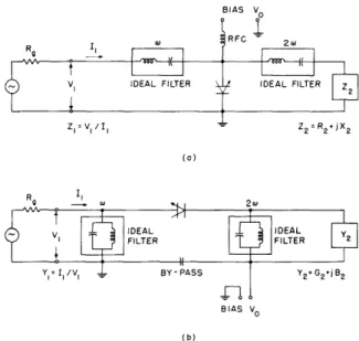
The problem is to determine how to imbed a nonlinear element in a linear network in order to vlmatch" the nonlinear element; that is, how can the maximum available power of a source at frequency w be converted to power delivered by the nonlinear ele-ment to the load at frequency nw ?
Theoretical and experimental investigation of the frequency doublers shown in
BIAS V0
BIAS V0
Circuit configurations for nonlinear capacitor frequency multipliers.
Fig. XXI-2 is now under way. Only fundamental and second-harmonic through the nonlinear capacitor in the circuit of Fig. XXI-2a, and only second-harmonic voltages can exist across the nonlinear element of Fig. XXI-2b. These conditions imply that power can be handled
current can flow fundamental and
in the circuit by the nonlinear Fig. XXI-2.
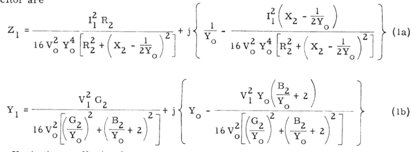
capacitor only at the two frequencies of interest, which greatly simplifies the analysis. Since the most efficient operation depends upon the impedance match between the fundamental source and the frequency multiplier with load, the input impedance of the multiplier is of vital interest. The approximate expressions that have been derived for the input parameters of a frequency doubler employing a semiconductor nonlinear
capacitor are -Il R2 0 0 L ( z S2Y V2 Y 1 2+ j1 16 V 2 [(G )2 ( B2 + 2 2 2
where Yo is the small-signal susceptance the other terms are defined in Fig. XXI-2.
1 Yo I 2(X? i -16 V2 Y4
I
X2 1)2 0 'X -2 1 o Y 16 V2 2 B 2of the nonlinear capacitor 2 2
at co and
REVERSE -BIASED P-N JUNCTION DIODE
/ IY 2
Fig. XXI-3. Measurement circuit.
These equations apply in the case of a semiconductor nonlinear capacitance of the form C = C1(P - V) , where C is the intrinsic bias of the p-n junction, V is the applied voltage, and C1 is the capacity at (p - V) = 1 volt.
Preliminary experiments have supported the validity of these expressions. Measure-ments were performed with the circuit of Fig. XXI-2b as shown in Fig. XXI-3. The bridge in this circuit is used to measure input admittance and also acts as a low-impedance source at frequency wl. From measurements of V1, V2, Y1, and Y
2, the
efficiency and input admittance of the harmonic generator are determined.
This work will be extended to the analysis of higher-order frequency multipliers. D. B. Leeson, S. Weinreb
(la)
(lb)
and
References
1. J. M. Manley and H. E. Rowe, Some general properties of non-linear elements. Part I. General energy relations, Proc. IRE 44, 904-913 (1956).
2. M. M. Fortini and J. Vilms, Solid state microwave power source, Digest of Technical Papers, Solid-State Circuits Conference, Philadelphia, Feb. 12-13, 1959.
C. NUMERICAL METHOD FOR DETERMINING POLE-ZERO LOCATIONS
The problem of determining the pole-zero pattern associated with a given magnitude-phase plot is often solved by a piecewise-linear method, either by using a Bode analysis or various curve-fitting schemes. An iterative method that uses the principle of analytic continuation is being investigated. The procedure involves applying the Cauchy-Riemann conditions to the data prescribed along a vertical line in the s-plane, and from this determining the magnitude-phase information at points along a second line that is close
to the first. The second line can then be used to determine a third, and so on, until a pole (or at least, a point of great magnitude with respect to its neighboring points) is reached. By examining the slope of the magnitude curve the location of the first (nearest the imaginary axis) pole is bracketed by two mesh points. If computation were con-tinued for succeeding vertical lines, still greater magnitudes would be found because the differential equation dictating the computation assumes the function to be analytic. Instead, the effect of the newly found pole is subtracted from the signal data and the computation is begun anew to find the pole next closest to the imaginary axis.
A program for the reverse process, computing the magnitude-phase information given the pole-zero locations (this is the important subroutine of the main program), is being run at the Computation Center, M. I. T., and the main program is being written. A simple, but approximate, method for determining the radius within which the signifi-cant poles and zeros lie has also been found.
A detailed analysis of the stability of the iterative process, the effect of mesh size, and problems of multiple order and closely spaced poles have yet to be considered. An alternative procedure wherein the peaks and valleys of the magnitude characteristic are used to give a first estimate of the dominant poles and zeros is also being investigated.
The complete program will be of use to both the circuit analyst and synthesizer: the phase-magnitude relations of complicated circuits at complex frequencies can be simply determined, and the rational function describing a given phase-magnitude characteristic, from which a circuit can be synthesized by using standard techniques, can be found.